The Journey

I'll be honest,
making a electric conductive guitar is quite a challenge for me,
seeing as I come from a different background and not engineering or Design

The idea for a conductive electric guitar was not my original idea,
but it is a platform I want to use in order to teach/encourage people,
with a physcial disability about not only the guitar but hopefully music.

Planning for my Final Project

K.I.S.S

The 3D Printer

The first sketch for the guitar

Working out how it should work

To think of a project for this year’s Fab Academy, was a bit difficult for because, I had no starting point nor the experience of making / inventing. I settled on making my own design of existing projects, out in the community. I came across two projects: Open Bionics and Bare Conductive .

For my current skill level, trying a bionic arm would be too much and hence I decided to go with a conductive paint project.


The Sketch you see is, based on the Les Paul Gibson 1957 body, heavily modified to be a bit more interesting (edgy…-lord?).

This is not the final design and am not happy with it, but it will do for now. I will need to understand how the touchboard controller from bare conductive works in order to try and make my own version.

Thanks to my fellow student John van der Zijden, I have the opportunity to play with the kit.

The design should be compact, portable and lightweight. The materials I am considering are cardboard, plywood or cured wood (bamboo, kalebas). This, of course depends on the material I can find and the time constraints. The idea of the electric conductive ink guitar (E-C Guitar)

is in this stage to be simple MIDI guitar, which will function as a toy/tool for enjoyment.

My hope is that, this will be used as a template to build it into a learning tool, for children and maybe even the physically disabled. Inspired by Vahakn Matossian from Human Instruments.


The main biggest challenge for me at this current stage is to be able to process the bamboo, in order to use a laser cutter or mill to create the body. My backup plan is to either cut it from plywood or MDF or cardboard.

I do want to use the skill acquired during these months in order to learn more, on how each machine it’s process works.

At first, I wanted to make a guitar, where the strings are painted onto the body with an electric conductive liquid/paint and this still holds true.

I think it is important to keep it compact lightweight, making it easy for portability and handling. And one way of doing this, is by making it modular.

I actually thought of this during the weeks 6 and 8. Late into the game, yes I know, but it started to make sense.

If I want to make it a learning tool for a younger audience, I need to make interesting and interactive.

If I want to make it customizable, make it modular.

Though this time around, I will just make one modular kit for the guitar and work on the design from that point as a reference.


My main goal for this year's FabAcademy is to make a working concept of a MIDI guitar with electric conductive ink for strings.


Final Project


BOM

Product Unit Price per unit
Cu Tape 5mm 1 piece $5.88
9 mm Plywood. 1 piece $30.49
Gorrila Wood Glue 1 bottle $3.15
Total Price $39.52

Design

3D Design

The software of choice, for 3D design is Fusion 360.

I wanted to use OpenSCAD, but I can always have a go at it after the academy

With Fusion i was able to create a template in Week 3 and from there build a modular guitar.


And with the Slicer extension for Fusio360, I was able to convert this to a 2D format.

The 2D maniupulation software I used is Inkscape. I chose this over Gimp, because I found the UI to be less cluttered and quicker to learn. I will be taking a crack at GIMP after as well.

Modeling the pieces of the Yggie in Fusion 360


Exporting the pieces one by one to the SVG format


2D Manipulating (only when required) in Inkscape


Getting ahead, I also used Inkscape for the design of the PCB enclosure.

The tool that helped me make the enclosure makercase.com

I modified the enclosure by using the method of subtraction, in order to create a passthrough for the cables.

PCB Design

Designing in Eagle was my go to, sometimes in KiCAD (week14) but most of the designs happened with Eagle.

For the desing of my final board, which is based on the FabDuino I actually made a mistake, I did not cloes the rest circuit all too well. Even if you have more experience in PCB design, mistakes can and will be made.

Stay vigilant.

That said, the board works perfectly well, once the reset circuit is closed and burning the bootloader and programming it were not an issue.


I used one analog pin for the controller and 6 pwm for the sensor pins. In between the controller and sensor pin are 10M ohm resistors.


Downloads:

Yggie STL:Download

Yggie Fusion file:Download

Yggie SVG 7z:Download

SRDuino enclosure SVG:Download

Coding


The software used for coding are VSCode for building the site, Arduino IDE for programming the boards and Processing for interfacing and networking.

In order to program the FabDuino, I decided in week 16 to get started and learning how to connect Arduino IDE with Processing.

Through testing and looking at existing sketches, I was able to use the Arduino Capacitive Sensor library, the Serial library to interface with Processing.


Coding the sensors

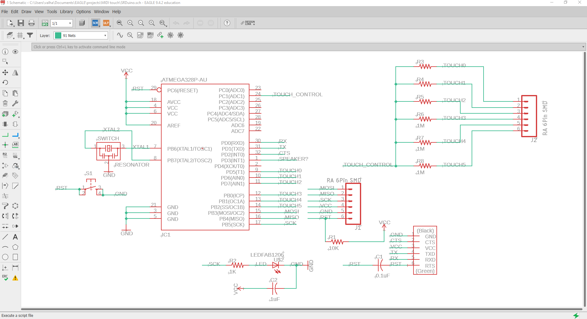
In order to assign the controller pin and the sensor pin I used the A1 pin for sending en digital pin 5-10 for recieving.

The naming convention, I left at default. CapacitiveSensorC_x_x = CapacitiveSensor(x,x)

CapacitiveSensor   cs_A1_5 = CapacitiveSensor(A1, 5);       // 10M resistor between pins A1 & 5, pin A1 is send pin, pin 5 is sensor pin
CapacitiveSensor   cs_A1_6 = CapacitiveSensor(A1, 6);
CapacitiveSensor   cs_A1_7 = CapacitiveSensor(A1, 7);
CapacitiveSensor   cs_A1_8 = CapacitiveSensor(A1, 8);
CapacitiveSensor   cs_A1_9 = CapacitiveSensor(A1, 9);
CapacitiveSensor   cs_A1_10 = CapacitiveSensor(A1, 10);
                                        

Initialization of the sensors. Though I now understand that it only can be written once, for cleaner code, I made it simple and defined each sensor individually.

void setup()
{
  cs_A1_5.set_CS_AutocaL_Millis(0xFFFFFFFF);  //Calibrate the sensor...
  cs_A1_6.set_CS_AutocaL_Millis(0xFFFFFFFF);
  cs_A1_7.set_CS_AutocaL_Millis(0xFFFFFFFF);
  cs_A1_8.set_CS_AutocaL_Millis(0xFFFFFFFF);
  cs_A1_9.set_CS_AutocaL_Millis(0xFFFFFFFF);
  cs_A1_10.set_CS_AutocaL_Millis(0xFFFFFFFF);
  Serial.begin(115200);
}
                                         

In order to define the threshold, samples and debounce of the sensors I used the #define component to give the names to constants.

For the threshold I defined it as total, which is given in the tutrial here.

The other were named sensor and replay.

With these constants I could calibrate the sensitivity of the sensors. TBH I thouhgt at first that I needed to define the threshold with the set_CS_AutocaL_Millis, but after looking it up, I realised the #define was what I was looking for.

For the loop, I used the datatype long capacitiveSensor(byte samples) in order to sense or unsense the capacitance. The control structures if, else are used to read the states of the thresholds and the boolean operators >, ==, && for comparing the values.

Do note that short int is used for debouncing purposes.

int state = HIGH;

boolean yes1;
boolean previous1 = false;

boolean yes2;
boolean previous2 = false;

boolean yes3;
boolean previous3 = false;

boolean yes4;
boolean previous4 = false;

boolean yes5;
boolean previous5 = false;

boolean yes6;
boolean previous6 = false;
short int a = 1, a1 = 0, b = 1, b1 = 0, c = 1, c1 = 0, d = 1, d1 = 0, e = 1, e1 = 0, f = 1, f1 = 0, g = 1, g1 = 0, h = 1, h1 = 0, i = 1, i1 = 0, j = 1, j1 = 0; //for debounce purpose

                                        
void loop()
{
  long total1 =  cs_A1_5.capacitiveSensor(sensor);
  long total2 =  cs_A1_6.capacitiveSensor(sensor);
  long total3 =  cs_A1_7.capacitiveSensor(sensor);
  long total4 =  cs_A1_8.capacitiveSensor(sensor);
  long total5 =  cs_A1_9.capacitiveSensor(sensor);
  long total6 =  cs_A1_10.capacitiveSensor(sensor);

   if (total1 > total) {yes1 = true;}
   else {yes1 = false;}

   if (total2 > total) {yes2 = true;}
   else {yes2 = false;}

   if (total3 > total) {yes3 = true;}
   else {yes3 = false;}

   if (total4 > total) {yes4 = true;}
   else {yes4 = false;}

   if (total5 > total) {yes5 = true;}
   else {yes5 = false;}

   if (total6 > total) {yes6 = true;}
   else {yes6 = false;}

   if (yes1 == true && previous1  == false && e)

   {


The part for reading and prinnting to serial is defined here.

if (state == LOW) {
    state = HIGH;
}
else
    state = LOW;
a = 0;
a1 = 0;
//   Serial.print(total1);
//   Serial.print("\t");
Serial.println('e');

}
if (yes1 == false && previous1  == false)
    a1++;
else
    a1 = 0;
if (a1 == replay)
{
    a = 1;
    a1 = 0;
}
                                        

The Serial.println gives a variable corresponding the E2 tone of the guitar tuning, made so to make it easier to read.

This piece of code is then repeated for the A2, D3, G3, B3 and E4 (which i called f in the serial line print).


Processing

As stated in Week 16 I used simple methods to draw simple grpahics and used the serial read to read the data created by the sensors and play a WAV sound.

In order to achieve this, I imported the MINI-M and serial library. Defined the WAV files and created a "data" folder , containing the WAV files.

The

import ddf.minim.*;
import ddf.minim.analysis.*;
import ddf.minim.effects.*;
import ddf.minim.signals.*;
import ddf.minim.spi.*;
import ddf.minim.ugens.*;
import processing.serial.*;

Minim minim;
AudioPlayer E2;
AudioPlayer A2;
AudioPlayer D3;
AudioPlayer G3;
AudioPlayer B3;
AudioPlayer E4;


Serial myPort;  // Create object from Serial class
String val;     // Data received from the serial port

int r=0;
int m=1;
void setup()
{
minim = new Minim(this);
E2 = minim.loadFile("acoustic1_e2.wav");
A2 = minim.loadFile("acoustic2_a2.wav");
D3 = minim.loadFile("acoustic3_d3.wav");
G3 = minim.loadFile("acoustic4_g3.wav");
B3 = minim.loadFile("acoustic5_b3.wav");
E4 = minim.loadFile("acoustic6_e4.wav");


String portName = "COM5";                             //Change COM to the port number that your Arduino is connected, you can check the port number from arduino program.
myPort = new Serial(this, portName, 115200);

size(160, 160);
background(0);


}


void draw()
{

if ( myPort.available() > 0 )
{  // If data is available,

val = myPort.readStringUntil('\n');
if(val!=null)
{print(val);

if(val.charAt(0)=='e')
{
E2.rewind();
E2.play();

fill(0, 0, 0);
rect(0, 0, 160, 160);
fill(255, 255, 255);
textAlign(CENTER);
textSize(50);
text("E2", 80, 90);

}
                                        

The void draw() is repeated for every note.

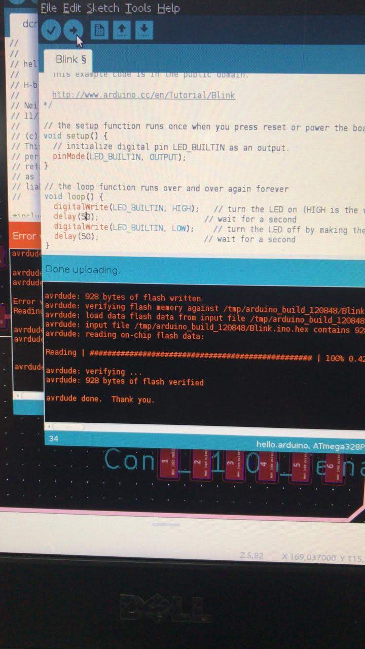
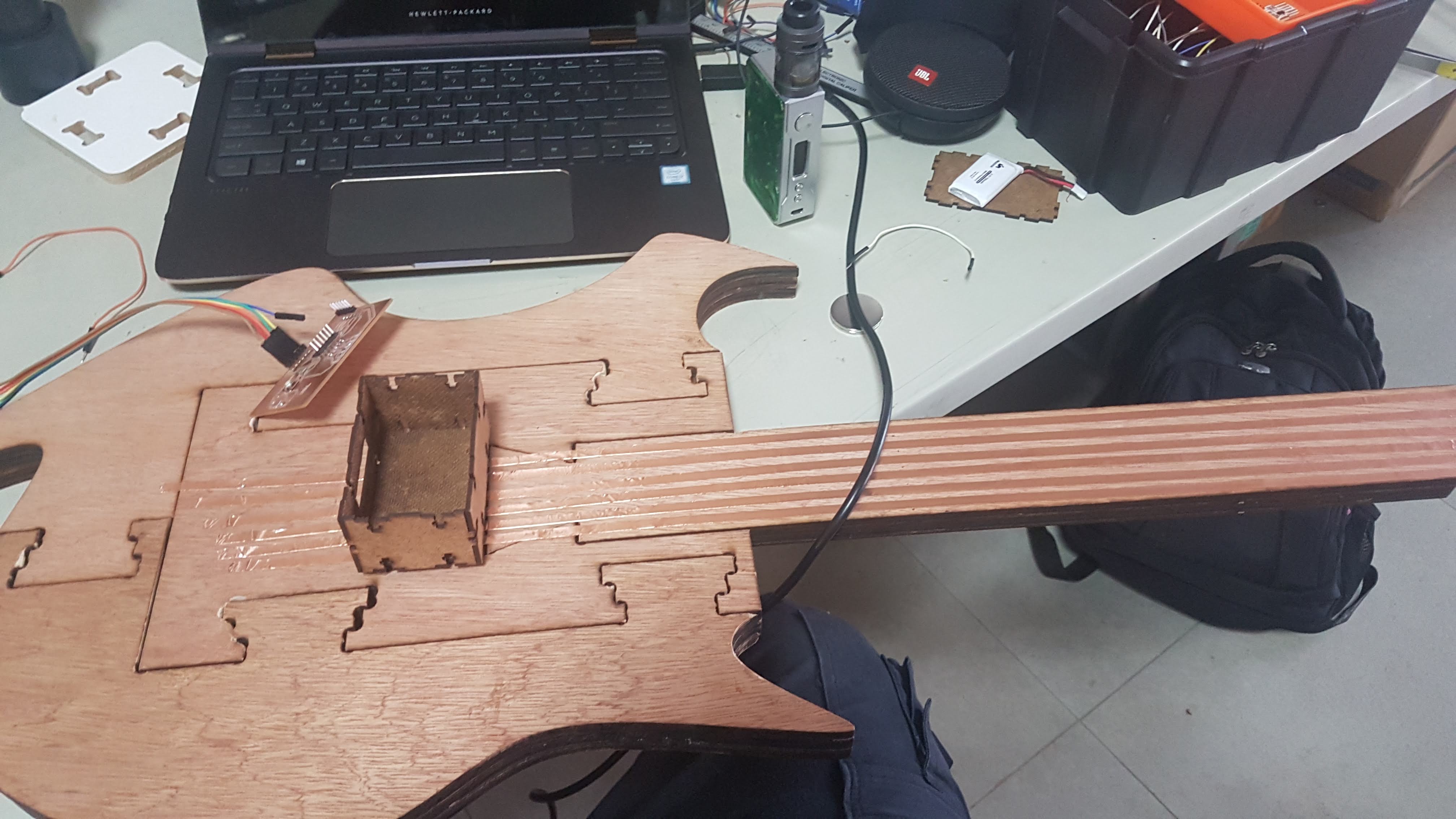
Here are the test results:

The 3D Printer

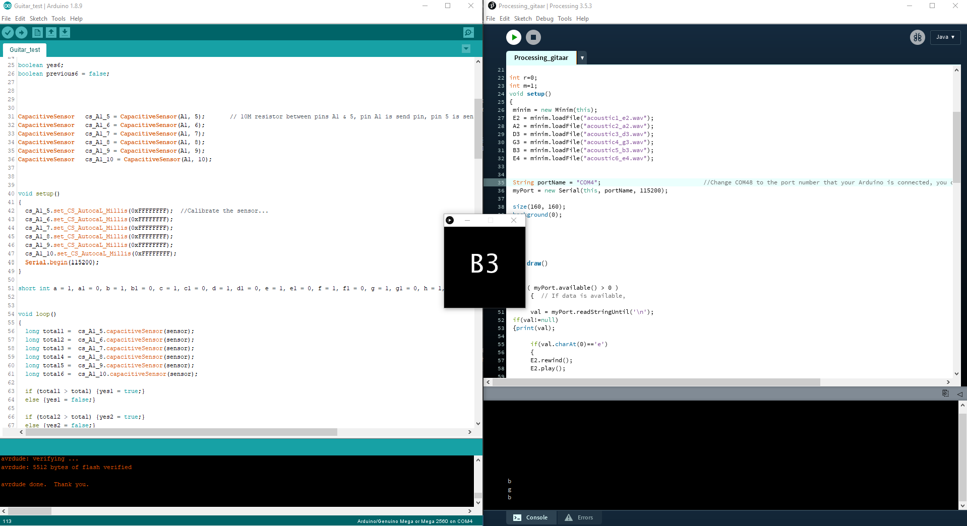
Testing it with the Arduino Mega 2560.

Assembly


The assembly of the guitar was pretty quick once the parts were lasercut.

The parts needed to be glued together, in order to become one whole piece of 30 mm thick.

All the pieces fit nicely togeter (after some sanding here and there) and I was off to program the board, after testing the blink porgram first.

MIlling the PCB

Time to stuff the board

Burning the bootloader with FabISB

Testing the program uploade

It's Blinking.

Assembling the Guitar pieces.

Finalizing the assembly.


The issue I ran into when testing the guitar with, long strips of copper tape, was that then sensitivty was off. It was either not platying, or playing constantly.

As mentioned earlier, I thought the set_CS_AutocaL_Millis() needed to be defined for the capacitive calibration, but I culd not figure it out, until I used the #define parameter to calibrate the threshold.

After playing with the threshold values, I was able to play notes with the sensors, pretty stable.

The final testing can be found in the video at the beginning of the page.


Downloads:

The PCB gerber file:Download

The guitar Code file:Download

The processing file:Download

The processing WAV file:Download

Special thanks


Neil Gershenfeld

IoT Lab

Ministrie of Commerce & Industry

Juan Carlos de Miranda our Instructor

Fellow Students:
    Theo Boomsma Julie Sundar John van der Zijden Dave Simson Elvira Rodgers Shafier Abdoelaziz

Anar Abdullayev

Software Used for this project: Fusion 360 Eagle CAD Arduino IDE MS VSCode Paperkit 2 Handbrake (Video compression) Camtasia Studio (Video/Audio recodring/Editing) Firefox Candle GRBL Controller FlatCAM PCB CAD/CAM WinPC-NC Inkscape Processing 3


License

License for my project

(c) Pascal A. van Lierop 2019 This work may be reproduced, modified, distributed, performed, and displayed for any purpose, but must acknowledge "Yggie Modular Guitar"(c). Copyright is retained and must be preserved. The work is provided as is; no warranty is provided, and users accept all liability.