Group assignment

Characterize the design rules for your 3D design and Print production process

The group Assignment link can be found here: Week 6 Group Assignment

Ultimaker 2 Extended

The Ultimaker 2 Extended

Testing the 3D Printer

For the Group assignment we had a 3D model to test the capabilities of oru 3D Printer. We used EasyFil silver colored PLA from Formfutura. This filament, is rated as following:

  • 1,75 mm, 2,85 mm
  • Food Safe
  • 750 g, 2500g
  • 180 - 220 C Recommended processing temparature

Filament

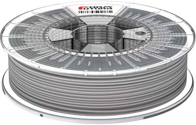
EasyFil Silver PLA by Formfutura

Printing the test model
Before we got to printing the model, we first need to pre-heat the printer to 220 C and extrude any lingereing filament that could hinder the process. We fired up Cura, which is the software, that converts image into readable gcode for the printer. Here we could change any parameter required for any 3D-printing job. However we used the recommended settings to test the model. If anything was off, we would then change these parameters.


Our Piece was modeled in TinkerCAD and would test various thicknesses, hole diameters and inlination positions. It also has a pyramid to test the material bonding.

  • Wall thickness: 0,5mm - 4mm
  • Hole Diameters: 1mm - 3mm
  • Spacing Distances: 0,1mm -2mm
  • Inclination Angle: 45 degrees- 80
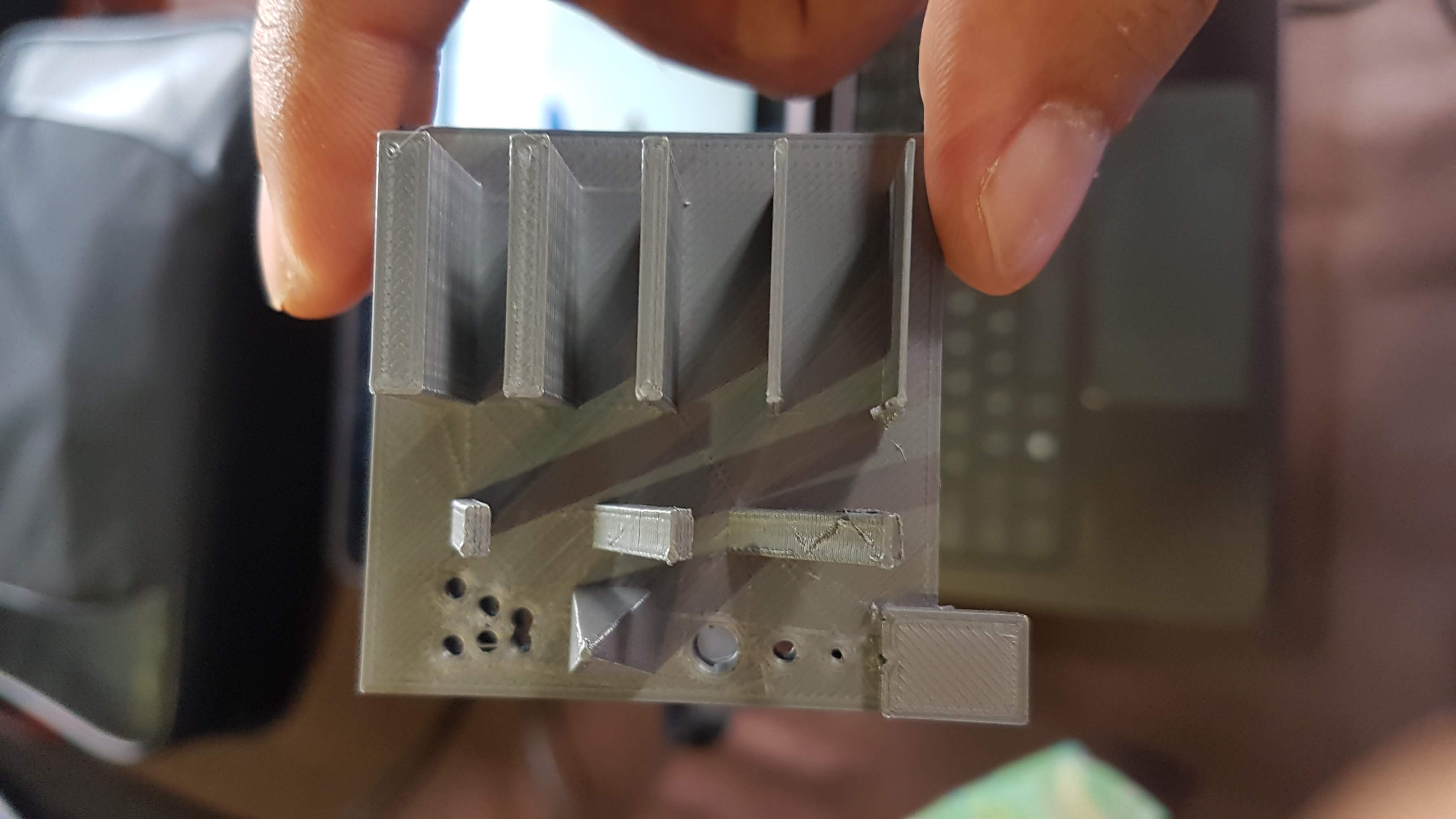
View Test Model

Top View

View Test Model

Right View

View Test Model

Diagonal View

To our delight, The fresh filament and the recommended settings of Cura, made for quite a clean print. WIthout any support settings the different angles and pointed tops were quite clean.

Only the overhanging piece was somewhat failed, but nevertheless, it was more than decent. The settings were not in need to be changed.


Individual Assignment

- design and 3D print an object (small, few cm3, limited by printer time) that could not be made subtractively
- 3D scan an object (and optionally print it)

Model from an image

We had to model a 30mmx50mm model, in order to keep the printing times down (a max of 1hr)
So, I could not print anything of my final project, at least nothing came to mind. So I decided to model a PC mouse.


Why a PC Mouse?

Our assignment, is to create a non subtractive design or rather an addative manufacturing proccess and what better to make such a design, sculpting a mouse with lots of curves?

This cannot be made by a laser-cutterm but rather with thermoplastics such as polylactic acid (PLA).

I searched for some images as my template for the mouse and ended up going with this one SteelSeries Rival100

SteelSeries Rival 100


This functioned as the basis for the sculpt, But the design is wholly my own.


I imported the png image to Fusion 360 and needed to calibrate it with the calibrate function of Fusion 360. This was needed to create a dimension for the canvas.

After I had set the postion and the dimensions with the calibrate function, I proceeded to draw a box on the top plane in Fusion 360.

reference image

Calibrate the reference image for the Postion and the Dimensions

Create Box

Box Creation

In order to have symmetrical faces on the 3D box, I mirrored the top face of the box with its opposing face.

parallelfaces

Mirror The Faces

Now with the mirrored faces, I want to flatten the bottom of the box and in order to do that, I select the "Bottom" view in the perspective tool. I then proceed to select all bottom faces and right click to select "crease" This will flatten out the rounded edges of the model, but there will still be some curvatures from the other faces.

In order to flatten the creased faces, we reselect all faces and in the "Modify" list we select the flatten command. We now have a flat surface.


flattenfaces

Flatten the Bottom of the Box

From here, we can sculpt the model according to the reference image

Sculpting

Sculpt Mouse to the reference.

I followed this tutorial, for the basis for the sculpting


Finish the sculpting in your own vision of any 3D model the wy you want to, but coming back to the mouse.
I wanted to add a scroll wheel. In oder to do this I first tried to cut a 3D sphere in 3 pieces. This was not the best method, because once I started to move the middle piece away from the cut, it became whole again. Cut Sphere

Tried cutting the sphere

What I ended up doing, or the mouse wheel is making a new Body and a new Component.
This method assured met that I could meld the new component into the new body, which I cut into the sculpted mouse.

Result Wheel

The Results are not that bad

3D Printing the Mouse

Export it to Ultimaker Cura

We are using the Ultimaker 2 Extended and it integrates nicely with the Autodesk software.

We just need to select the Make function and a window will pop up with the options required to select Ultimaker Cura.

Export as STL for 3D printing

Description of Make function in Fusion 360

Export as STL for 3D printing

Export to Cura

Export as STL for 3D printing

Prepare Print

And this is the resulting product:

Front View

Front View

Right View

Right View

Left View

Left View

TD View

Top-Down View


Downloads:

Fusion 360 PC Mouse file

PC Mouse STL file

3D Scanning

Alas this assignment is still pending, The Sense 3D scanner by 3D Systems, for me and fellow student Dave Simson, kept losing the object we wanted to scan. I suspect the version software. We installed version 3.0.213, but the others were using V2.2

Our follow-up is to try again at a later date. We wanted to test it with the Xbox 360 Kinect, but we do not have the correct USB as of yet.

TD View

The Sense Scanner in action...or at least somewhat

TD View

Intuitive Mounting system for the scanner

3D Scanning

The scanner we used is the Sense scanner from 3D systems.

TD View

Sense scanner by 3D Systems

Sense Scanner Value
Operating Range Min: 0.4m-1.6mm
Filed Of View Hor:45, Ver:57.5 , Diag: 69
Operating Temperarture 10-40
Maximum Image Throughput 30 fps
Scan Volume 0.2mx0.2mx0.2m - 2mx2mx2m
Linear Cutting Force 68kg
Depth image size 640x480 px
Spatial x/y resolution @ 0.5m 0.9 mm

The 3D scanning process, was conducted in a normal lit room, and the target was my chinese prayer bracelet.

The way we worked is to string up the bracelet with some rope to susspend it from the air.

This way,we could easily walk around the object, in order to get a good scan.

We noticed, that in order to have the best 3D scan, the conditions need to be as following:

  • Lighting Condition: Low - Normal
  • Ideal Distance (for objects): ~50cm
  • And walking at a snails pace.

TD View

Getting Help from Fellow Student Dave Simson

TD View

Our way of doing the 3D scan.


We had some fun poking jokes at the scanner and the scan process, but in the end the result came out pretty nice.

The procedure to make the scan into a 3D object, we need to take these steps:

  • Edit (Crop or Erase)
  • Solidify
  • Enhance (Touchup or Trim)
  • Save
TD View

Crop or erase any anwanted objects the scan picked up.

TD View

Enhancing the scan.

TD View

Enhancing the scan.

TD View

Solidify the scan, once the unwanted objects are removed.

TD View

Touching up the rough edges.

TD View

The results of the chair.

TD View

The results of the beads.

3D Beads file:Download

3D chair file:Download