Group assignment

Test the runout, Alignment, Speeds, Feeds & Toolpaths for your machine

The 3D Printer

The prototype

The group Assignment link can be found here: Week 8 Group Assignment


Individual assignment

Make (design+mill+assemble) something big

Drawing the modular guitar

In order to draw the guitar, I first tried to shape it, but quickly realized that I will need the dimesions for the milling.
After my realization, I quickly started with a "slab". From the slab I designed the main body, left and right wing and the neck.

These are the parameters, I used for the design.
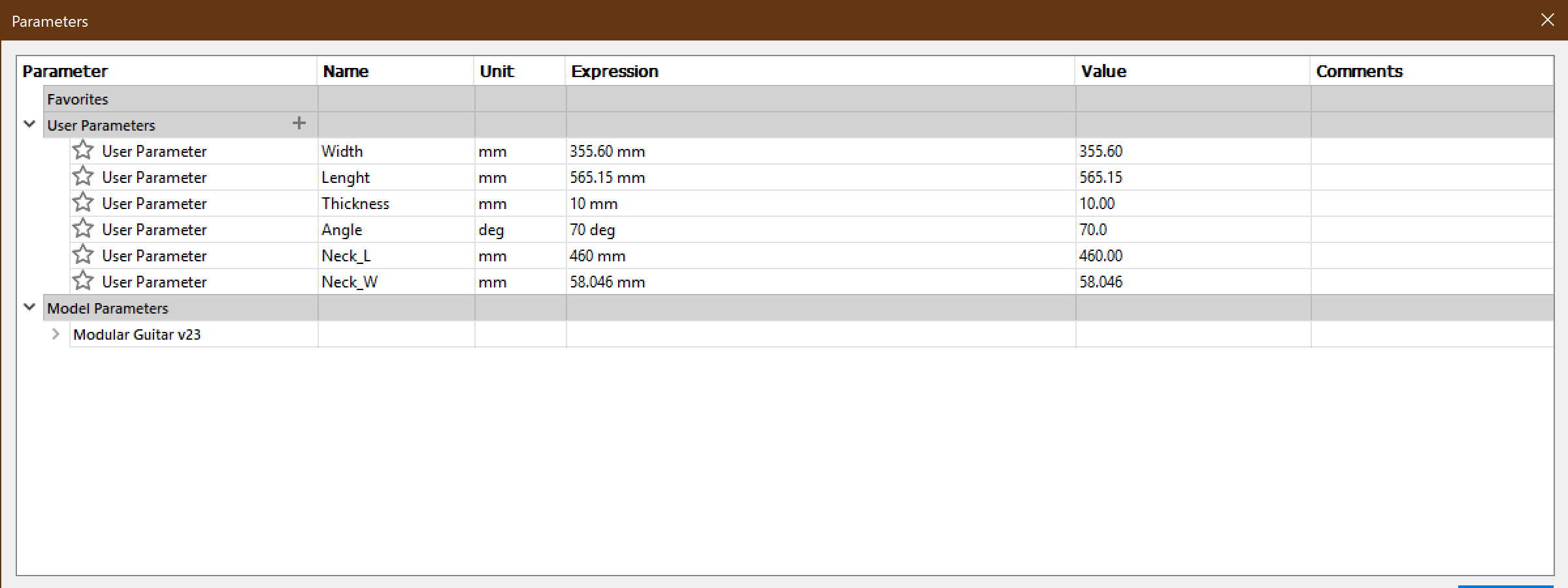
 Sketch Dimensions

Sketch Dimensions


After I sketched the slab, I extruded it with the fomula -Thickness (remember which i predefined in my params)

After the extrusion, I created 2 more, with the Create->Pattern->Rrectangular pattern and with the formula -thickness*2.


reference image

Drawing the Slab


I used the stepping dovetails design, for connecting the piecese together

Create Box

Drawing the pieces onto the slab.

I then proceeded to finish the guitar, by adding the guitar neck to the sketch.

parallelfaces

Finishing the sketch

Now that I have all the pieces sketched, with my dimensions, it is time to extrude and cut the pieces from the slabs.


flattenfaces

Orient your design, for a better view.

Sculpting

Select the slab pieces to cut first. Use the formula -thinkness*3

After you have cut the slab, you are left with the guitar neck, which is still a sketch. Extrude the neck in order to create a new body element.


The extrude process is repeated for the left and right wing of the guitar.
Cut Sphere

Extrude the wings

Mistake numero um, do not extrude with the formula -thickness*3, but instead extrude the wings, with -thinkness and then create 2 extra wings with the rectangular pattern, otherwise, u will get one solid block per wing.


Result Wheel

The Results for extruding all the 3 pieces.


Result Wheel

What you really want if you want a 30mm thick guitar

The dog bone, as you can see was forgotten during the design, but I added the bones with a script that can be found on GitHub here.

The CAM Proces

Fusion 360 CAM

The reason, I choose F360, now more than OpenSCAD is the workflows integrated into the software. You can go from designing straight to generatign CNC code.

I have to admit, the interface for the CAM is somewhat getting used to, but you also need to understand the basics of CNC and its terminology.

I followed the provided tutorials provided by AutoDesk at their online courses, but I have to admit, that I am no expert at the CAM software....yet.

I have made mistakes with the design and with the CAM, but we will go in on these a bit later.


After we have our design, it is time to prep for the machining. The CAM process can be found in the dropdown menu on the Toolbar. the CAM feature is called Manufacturing.

Export as STL for 3D printing

Description of Manufacturing in Fusion 360


For this job, I selected 2D Contour. This because, I have no 3D elements (curvatures) in my design and no pockets, that need clearing.

Export as STL for 3D printing

2DCountour


After we have selected the type of job, we now need to set it up with the right parameters. So we create a new setup

In the setup, we need to select our 0 point and we can do this in many different ways, but I selected the box point (rather the upper-left edge of my stock)

Export as STL for 3D printing

The setup for the job.


And for the stock, I kept the stock size relative to the model and their positiong, because the measurements of the real stock was pretty close.

I just added a 2cm offset, as to not go beyond the edges of the stock, during the cutting.

The post processing, will be done at a later stage.

Front View

Setup for the origin point


Now that we have our main setup for our origin point and stock size, we need to select the tool we are going to use and define its features.

Right View

Defining the tool

The settings for the Shopbot (info for the machine can be found in the cutting section) are as following:

  • Tool Diamater: 6mm
  • Mill Flutes: 2
  • Spindle Speed: 14000 RPM
  • Feed Rate: 120 mm/s
  • Plunge Rate: 15 mm/s

Left View

How the machine should cut


In the geometry tab, we can define our contours, by selecting the bottom of our contours. Manually select the countours that are in your design.

And as you can see, I added some tabs in the cut, in order to keep the pieces from moving during cutting. These are 5mm wide and 1.5mm in height.

TD View

The default heights, defined by previous settings.

TD View

And the number of passes. The job will be run twice for finishing.

Meet The Shopbot PRSalpha 96-48-8

ShopBot PRSalpha Value
Clamping Surface (x,y) Full Size
Working Space 2490mm x 1270mm x 200mm
Step Resolution 0.0127mm
Maximum Speed (x,y) 15,24m/min
Axis Drive System Rack and Pinion
Linear Cutting Force 68kg
Software ShopBot

It is a great machine, that after some tweaking and maintenance (see out group assignment page) it was routing and maching great!

I had some hard lessons to learn here, going from Fusion 360 to the Shopbot software. The aircut.sbp was moving the x and z axis, but not the y.

The translation from Fusion to shopbot was changing some lines in the .nc code. And I noticed it put file in imperial system inches instead of metric mm.

As to not lose much time on the code, I exported all the components to SVG, imported them into LibreCAD and my instructor helped me clean up any translation blemishes.

We exported them to DXF and proceeded with Aspire software by Vectric.

TD View

Imported the DXF into Aspire.

TD View

Setting up the CAM for Shopbot


The Cut depth (despite the pic) was put to 10.25mm. My stock is OSB plywood of 10mm thickness. I measured with a caliper, eventhough it stated 11mm

It was obvious that the plywood had defiations (used) and this was an error on my judgment. The repurcusions were not that great however and managed to cut my desing, fairly well.

We proceeded with setting up the machine for its work load.

TD View

Imported the DXF into Aspire.

TD View

The 6mm, 2 flute bit.

TD View

The tools required to change the bit.

TD View

Setting the 0 point and using the touch tool.


And as you can see, The cut is very clean, but due to the cutting depth and the boards, inconcistencies some parts were not so nicely finished.

Some sanding and varnish later it does not look quite so bad.

TD View

Quite a clean cut

TD View

The finished cut.

TD View

Cleaning up the rough edges.

TD View

Putting 2 layers of varnish

TD View

The prototype.


What did I learn?

My take on this week's assignment, is to have a good workflow for designing and planning out your CAM process.

Always start with a sketch, make it 2d first and then make a model of your design.

Choose your material and measure twice before cutting a 100 times. This will save you time in the CAM.

Always check your code or any blemishes if there will be any translation. Not all software like each other even though the state so (Software updates make and break).

Always be ready for failure, the first time. Learn from mistakes made and keep at it.

Also, I asked my nephew of 4 years old what he thought of the design and how it fit. First thing he told me, is that it is too heavy but liked the design.

Next stop is making it lighter, tryin to translate the design into a, perhaps smaller frame.


Downloads

The mod Guitar STL

The Aircut File

The Aspire file

The DXF files

Week Complete