Group assignment

Characterize your lasercutter's settings, kerf and joint clearance

The group Assignment link can be found here: Week 4 Group Assignment

Lasercutter Walktrough

Lasercutter Walktrough

Meet The RobotSeed RS-1060 L

Our fellow student, Thibault Chevreteau, introduced us, to the RS-1060 L, which is a 90W CO2 tube powered lasercutter that has a work area of a 1000 x 600 mm. In other words, more than enough space for tryouts of the kerf.


Pin-pointing for the best settings
In order to start with finding the best settings for the lasercutter, we first needed a walkthrough of how the machine operates and how it is cooled, for practicing safety.
The 5S methodology is very important in the workspace. Before working with the cutter, we first need to switch on the air extractor, turn on the power of the lasercutter and check if the CW-3000 Industrial Chiller is also turning on. 2 Beeps will confirm.
Never leave the machine unattended! a walkthrough of the lasercutter

The 5S for the lasercutter

After the walktrough we started on the design, to try and find the kerf width. We initially used a power of 90% and a speed of 20% and a nominal focus of 8mm. This resulted in some deviations in performance. I.e. (too bad I did not take or make a video of it) the 5mm thick plexiglas was not cut all the way through with the design.
We proceeded with MDF-like material of 2mm thick. And the results are as following:
a walktrough of the lasercutter

Testing the laser

Test Power Speed Focus
1 30 % 20 % Nominal(8 mm)
2 60 % 20 % -1 mm
3 90 % 20 % -2 mm

Choosing VSCode as Git's default Editor

Cleaning the RS-1060 L Lens


The third test was done after a general maintenance on the machine (again... I made no fotos -_-) We discovered that the lens was not set in correctly. The rounded side of the lens was pointing downwards, all the while the manual shows us that it should point upwards....oops, but no foul! we found our right settings.
And time to start with the press fit kit.

Individual Assignment

Create a Press-Fit Kit

Create it

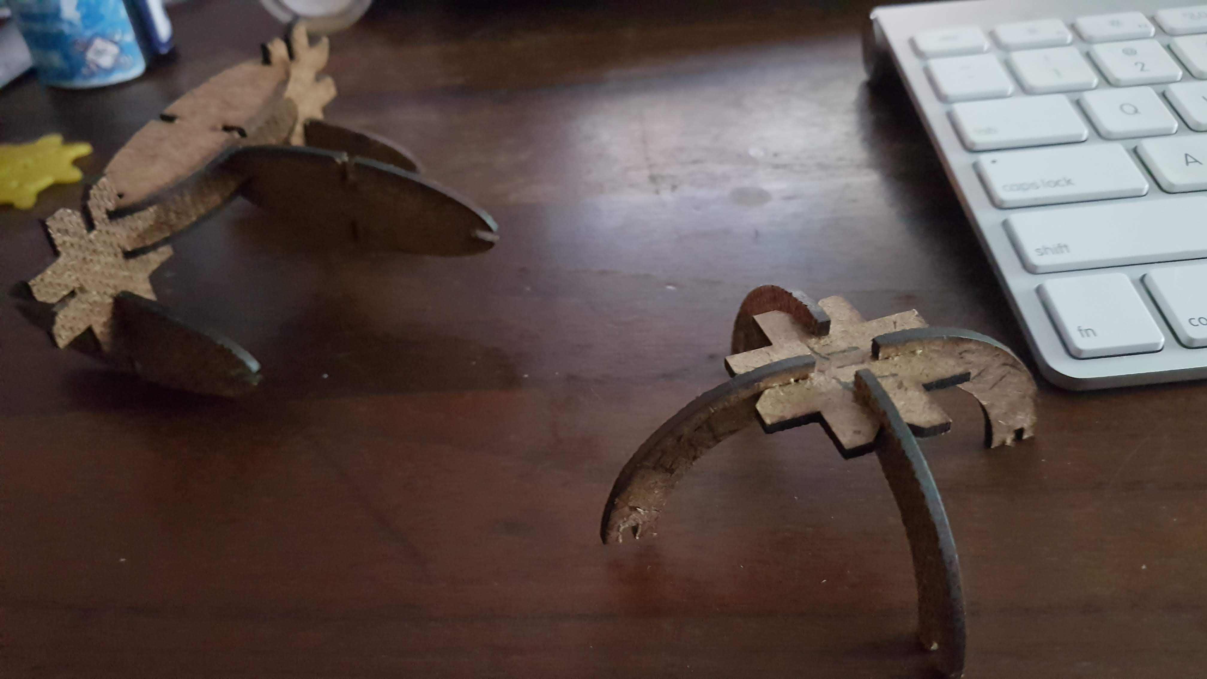
Drawing the idea for a press-fit kit

Creating a press-fit kit took me a while to grasp, becuase I did not want to make circular pieces, which can be stacked or connected. I wanted my pieces to kind of make sense.
At first I though of a transforming "arrow-man" into a guitar. This idea however seemed a bit to convoluted at the time and I will revisit this idea some day.

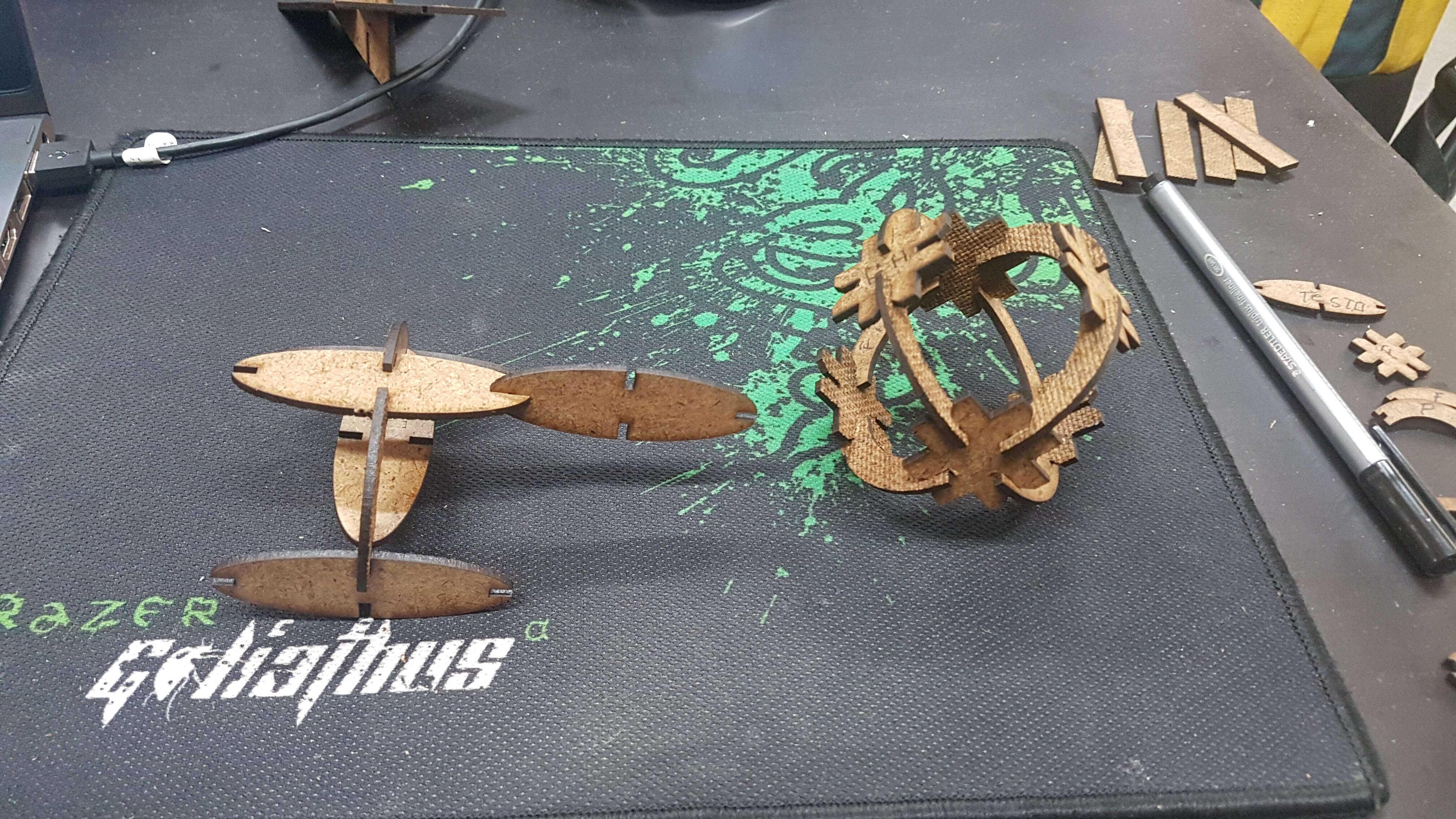
Plan B was to create a tank with an elipse, hex and crescent piece.
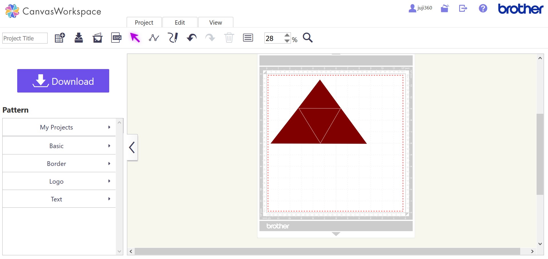
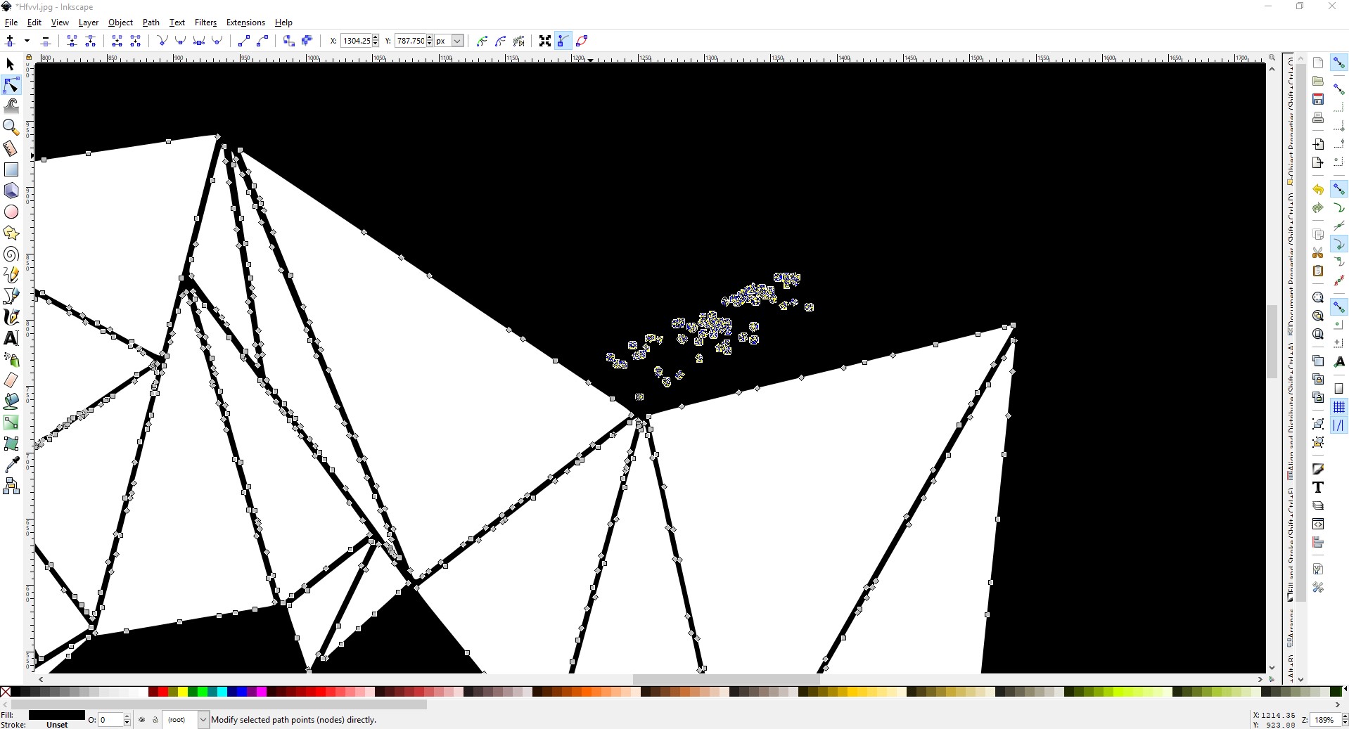
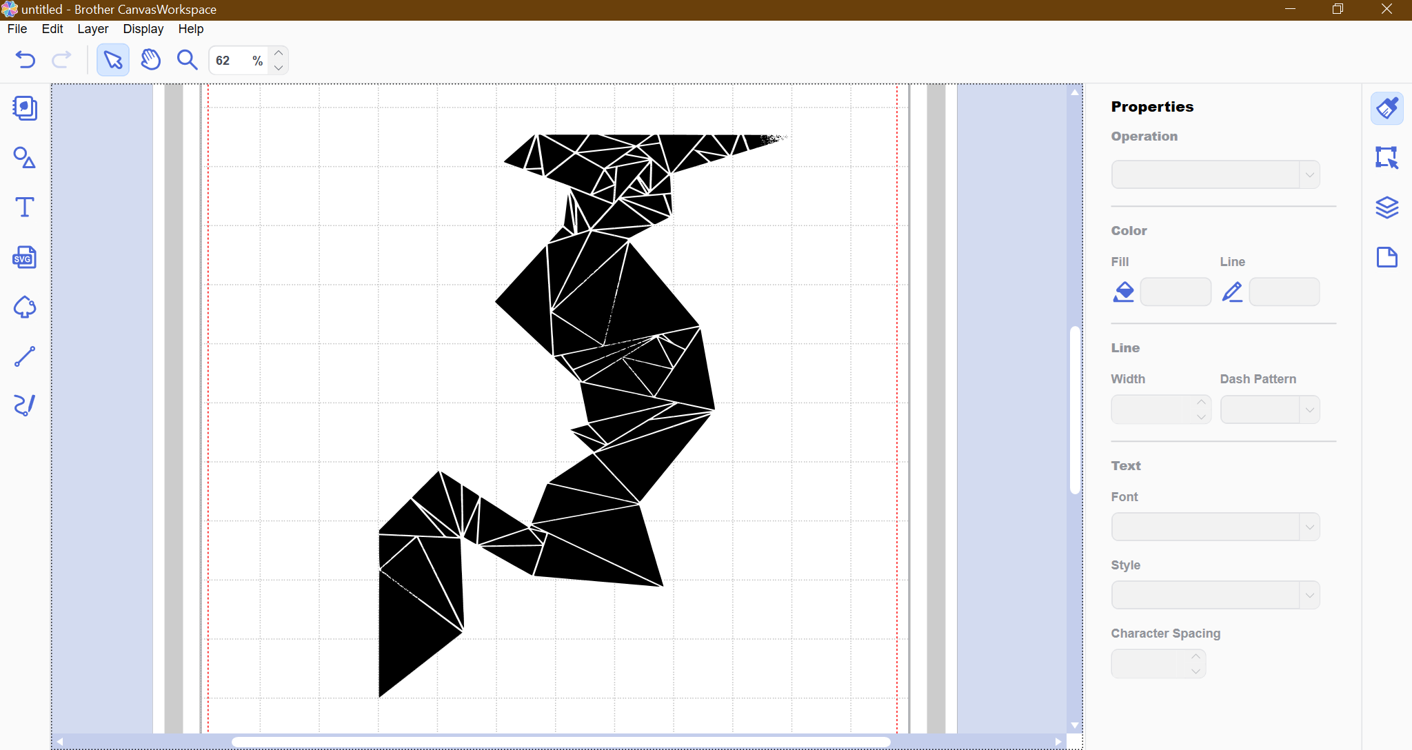
I sketched a drawing to have a general idea and went to work in Inkscape, tried my hand at Fusion 360 and ended up working in OpenSCad.
OpenSCad had an upper hand in this assigment, because the formula we found for the best cut, was directly programmable into the software.
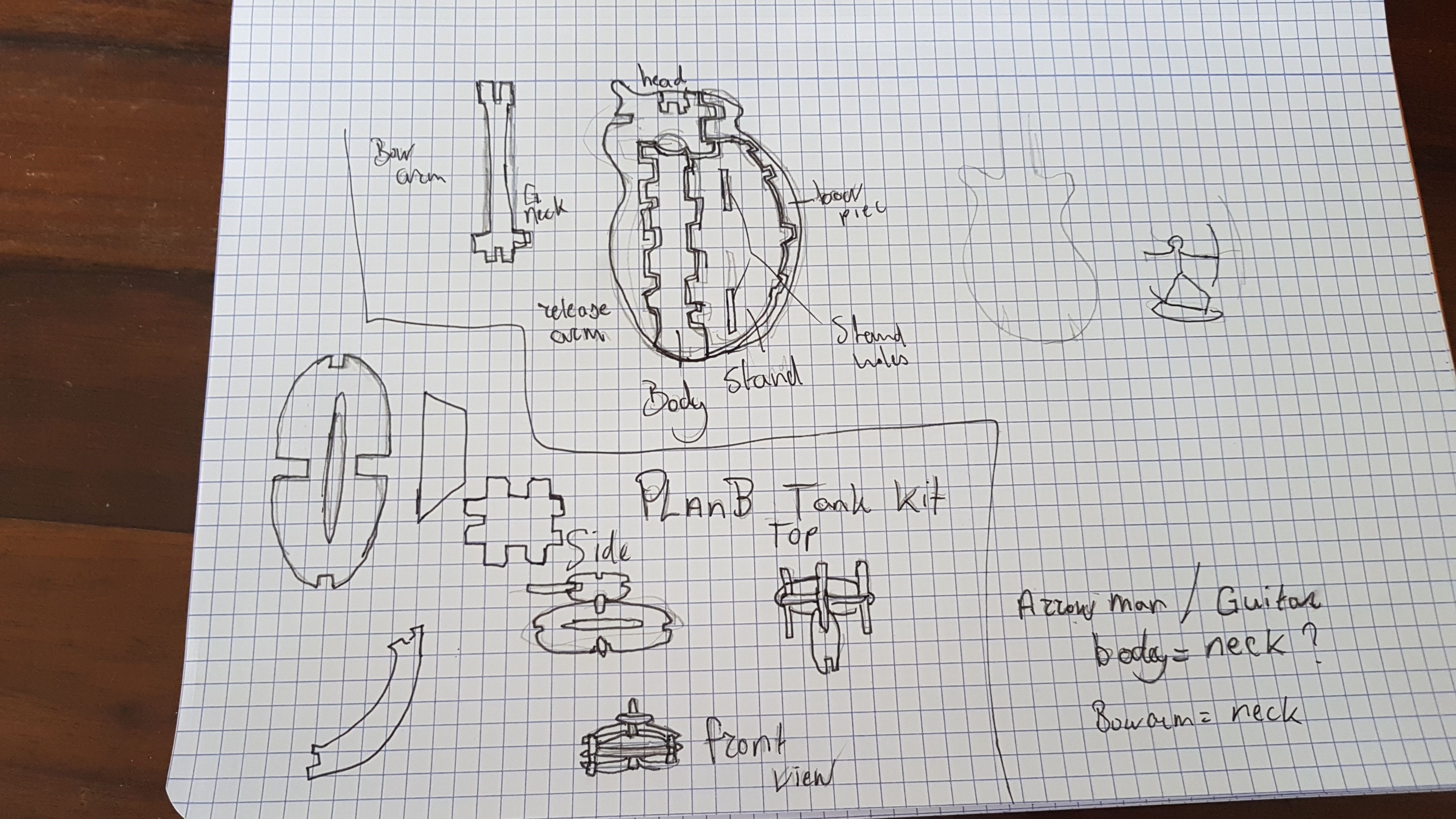
 From sketch

From Sketch

You can use GitKraken to generate you're RSA Key

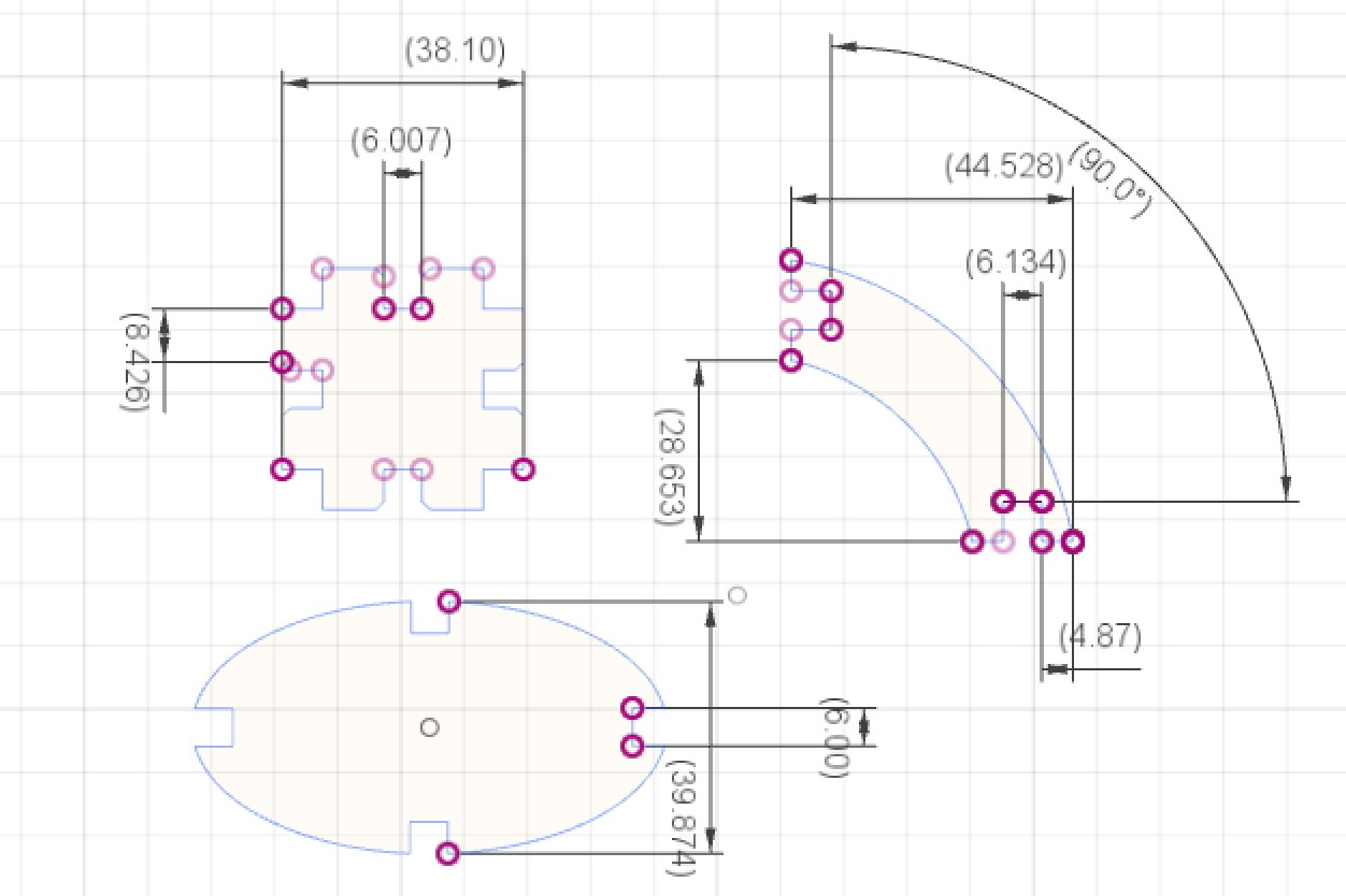
To trying out Fusion 360

Here I was just trying out my idea in fusion 360, but I did not yet know how to enter the paramaters, until I already went over to OpenSCAD.

Fusion 360, it's parameters are adjustable in the Change Parameters section under Modify. Or simply press Ctrl+P to enter you're user parameters.

You can download my Fusion 360 sketch press fit kit here: Download

You can download my Fusion 360 dxf here: Download


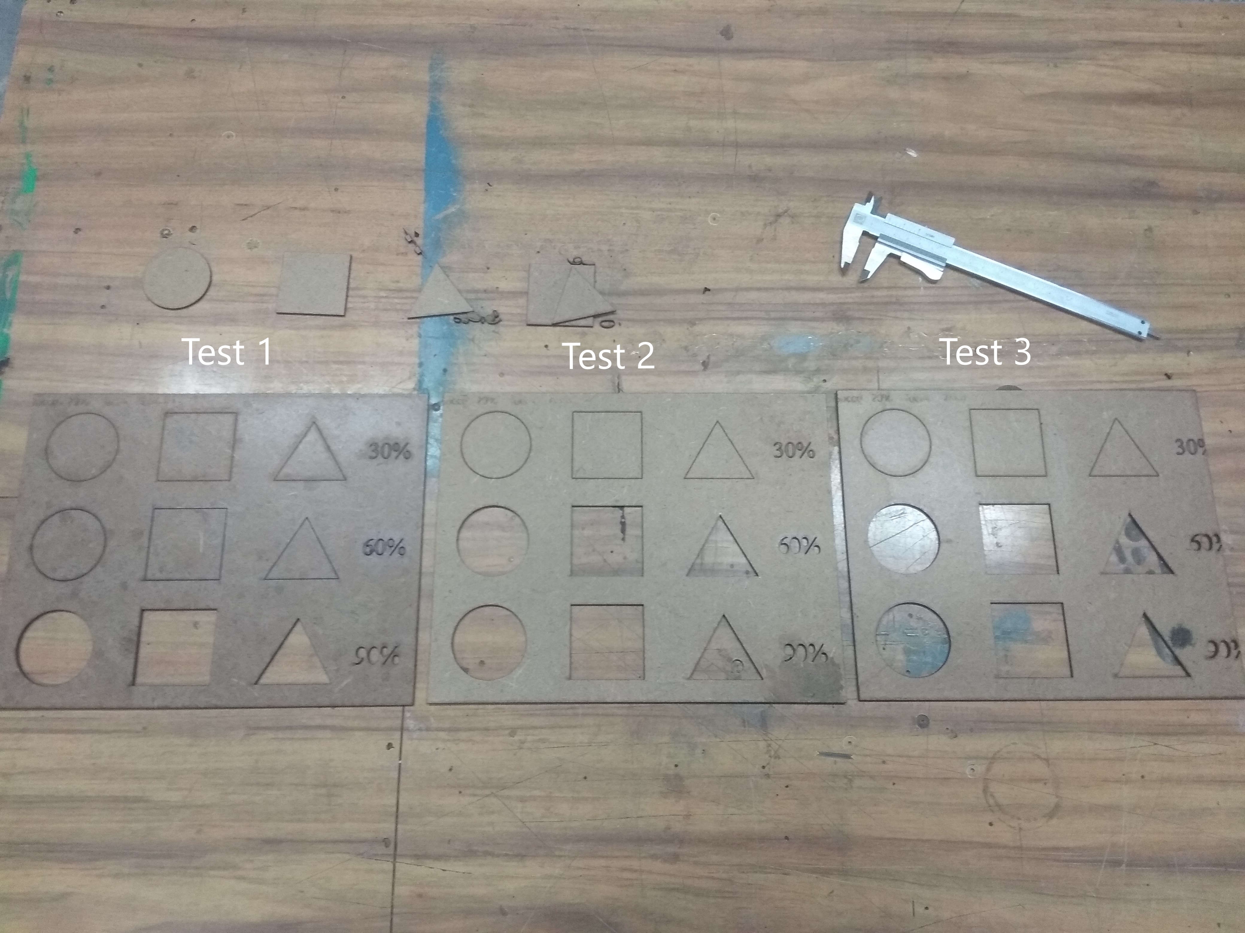
With OpenSCAD I could directly define the formula for the kerf with these parameters:
  • $fn=120;
  • side=30;
  • material=2;
  • kerf=0.05;
  • thickness=material-2*kerf;
*all parameters are in mm.
You can use GitKraken to generate you're RSA Key

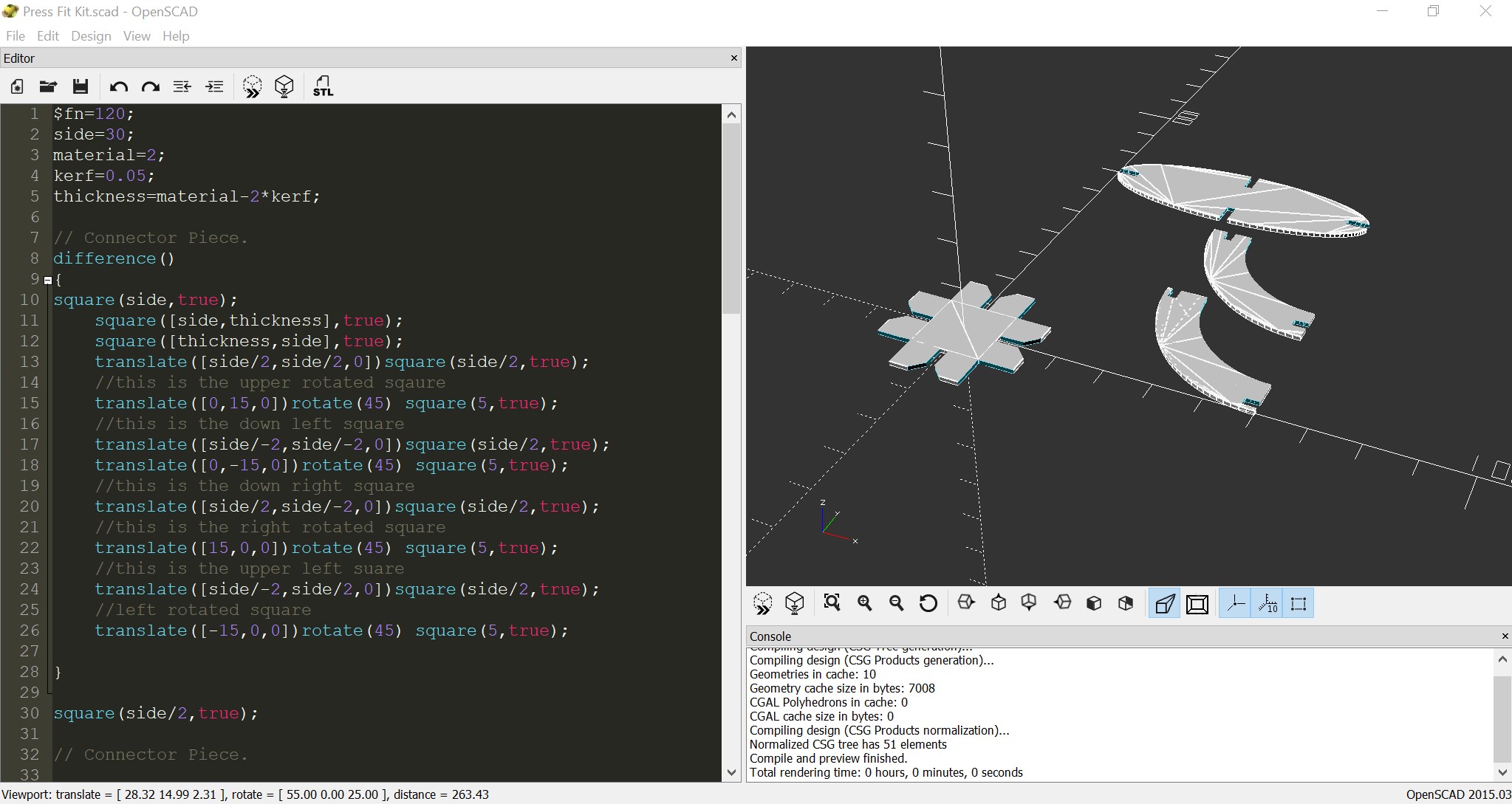
And ending up in OpenSCAD


Learning OpenSCAD was a bit of a challenge at first, but once you get the gist of how the language works, it is quite logical.


Source: wikibooks

Source here: OpenSCAD Wikibook.

object();

variable = value;

operator() action();

operator() { action(); action(); }

operator() operator() { action(); action(); }

operator() { operator() action();

operator() { action(); action(); } }

Objects

Objects are the building blocks for models, created by 2D and 3D primitives. Objects end in a semicolon ';'.

Actions

Action statements include creating objects using primitives and assigning values to variables. Action statements also end in a semicolon ';'.

Operators

Operators, or transformations, modify the location, color and other properties of objects. Operators use braces '{}' when their scope covers more than one action. More than one operator may be used for the same action or group of actions. Multiple operators are processed Right to Left, that is, the operator closest to the action is processed first. Operators do not end in semicolons ';', but the individual actions they contain do.


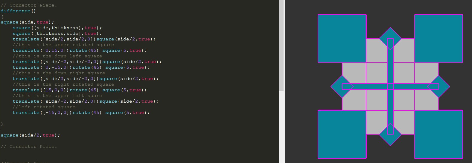
In order to create the hex connector piece, we start out with a square of 30 mm;

First we define the sides of the square: side=30;

And the thickness of each rectangle, which shall be used for the subtraction in the defined pieces: thickness=2;

Then we create the square: square(side, true);

Now, we create another square, that will be turned into a rectangel. This will be splitting the sqaure in horizontal half (remember, x,y,z axis)
square([side[ x axis],thickness[y axis]],true);

In order to split the difference of these two objects, we need to place them in an operator called difference()
We no open the brackets to bring every statement that has to do with the sqaures under the operator

So it will look like:

difference()

{

square(side,true)

square([side,thickness],true);

square([thickness,side],true); (we switch axis making the rectanlge stand vertically)

}

The same can be done with other objects and here you have the resulting outcome of subtracting and adding shapes into OpenSCAD

Hex Piece

Subractive

You can download my press-fit code kit here: Download
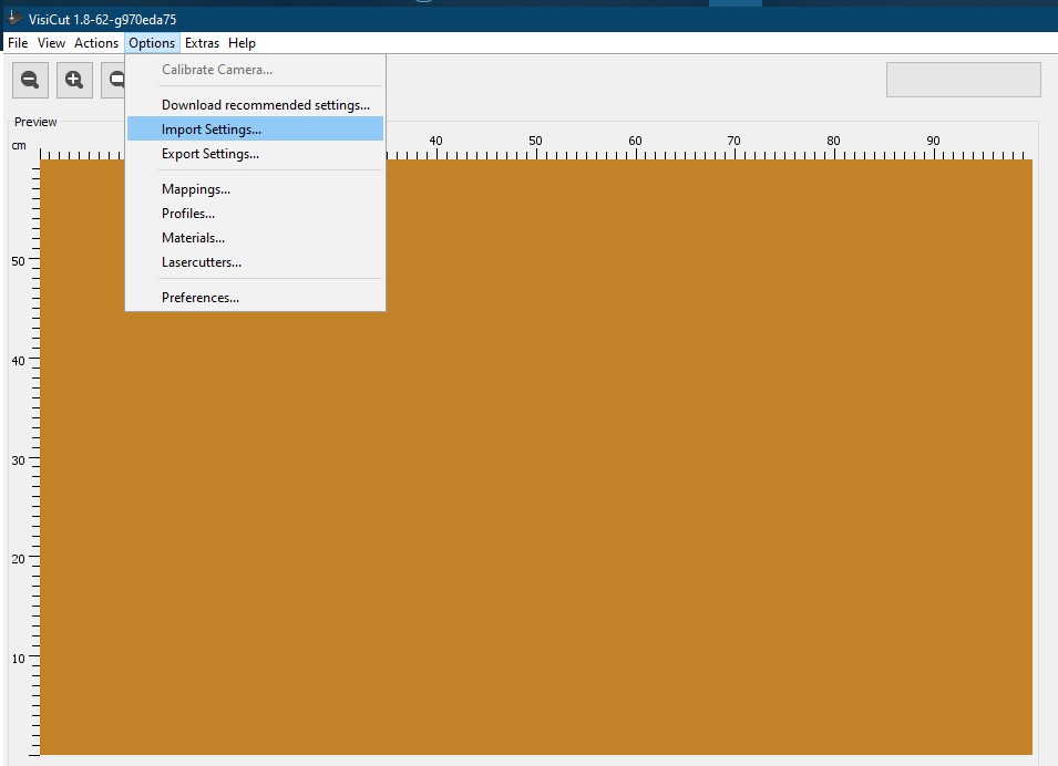
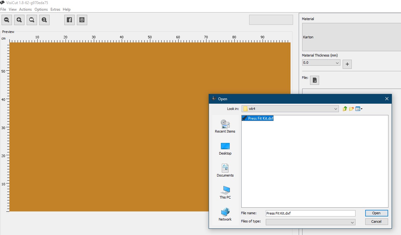
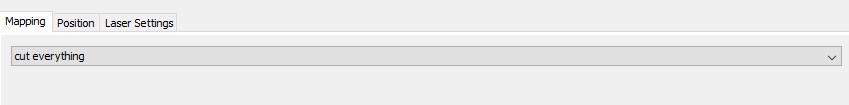
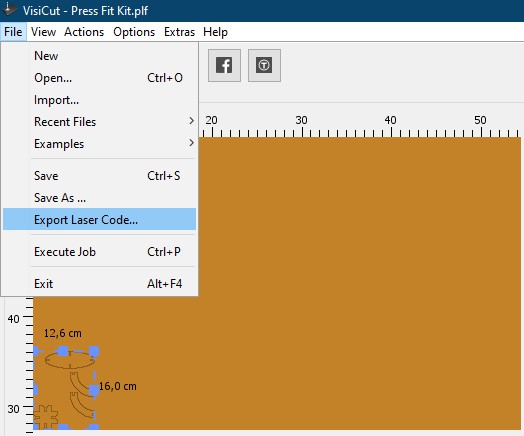
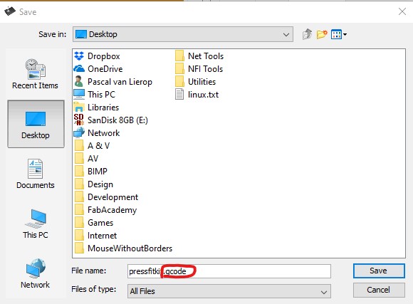
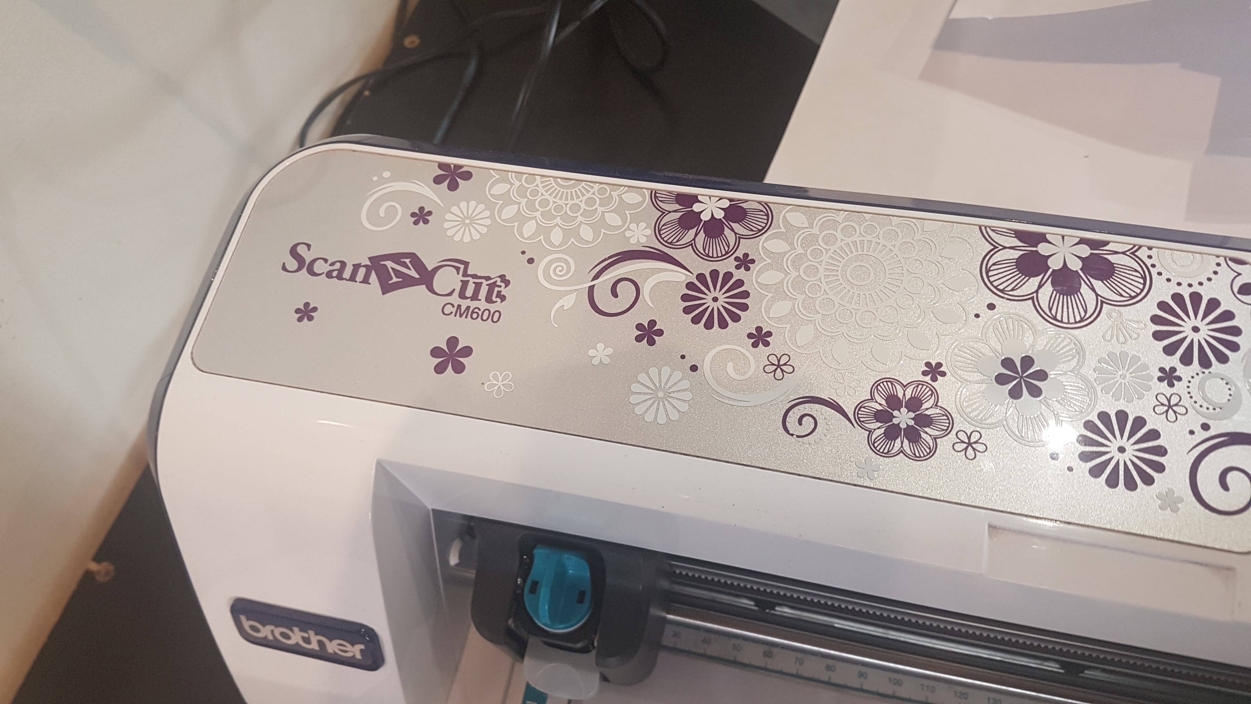
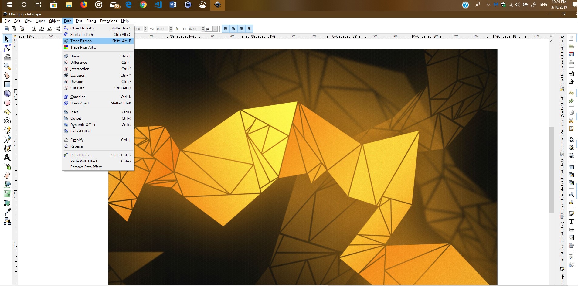
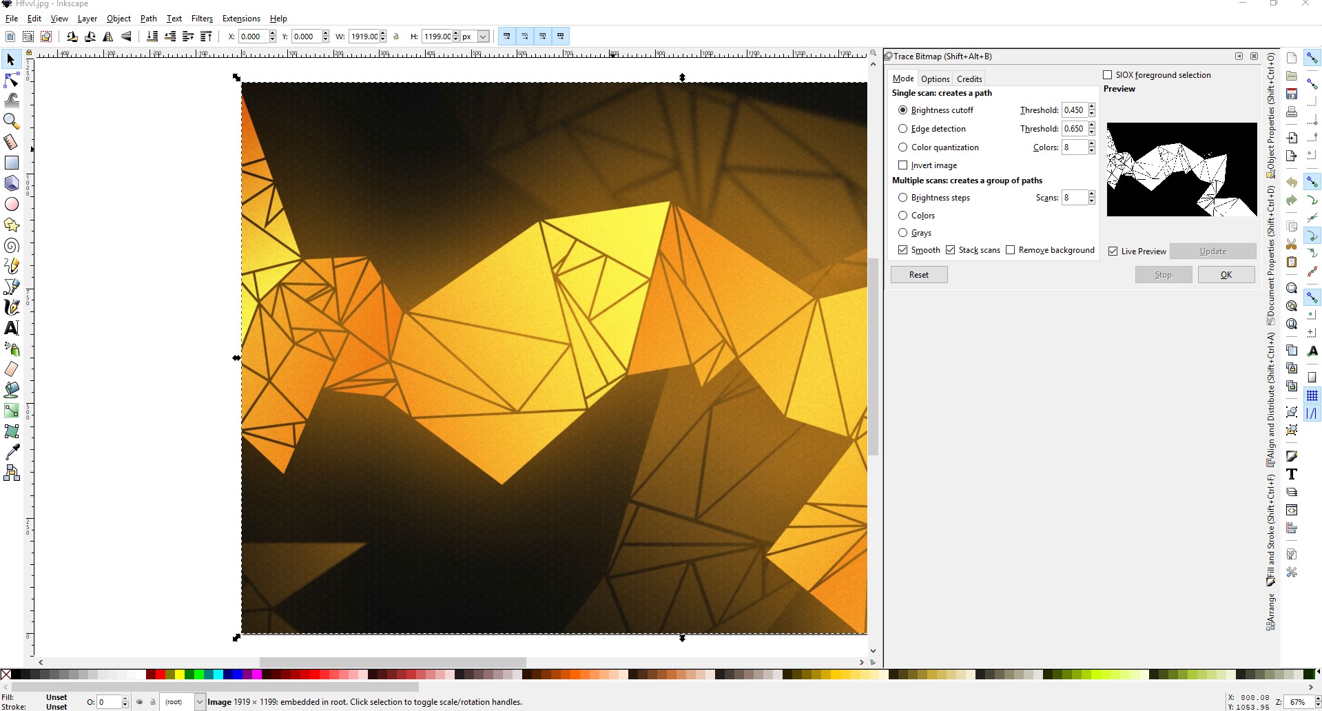
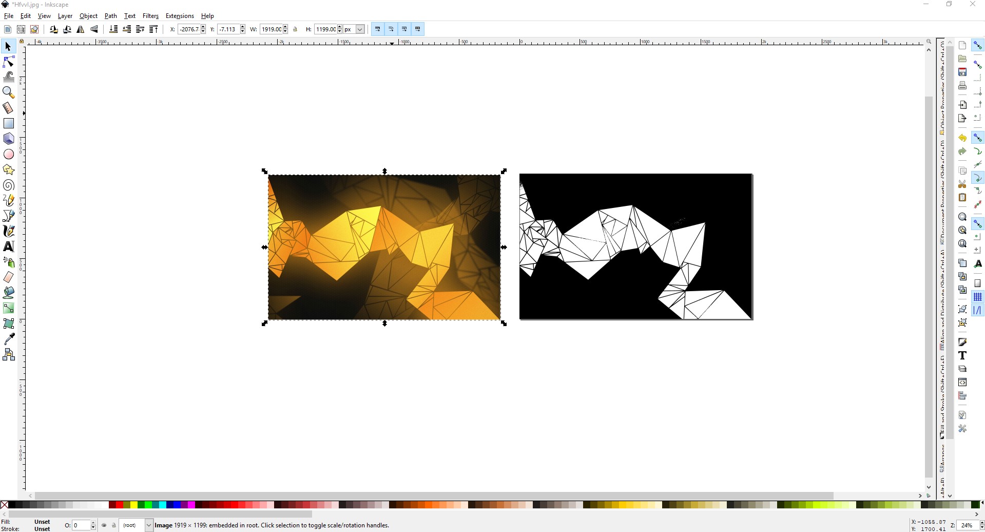
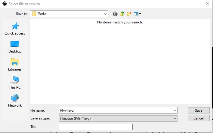
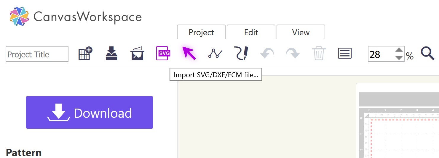
Export it to DXF
Visicut

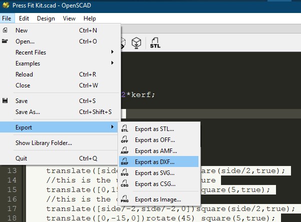
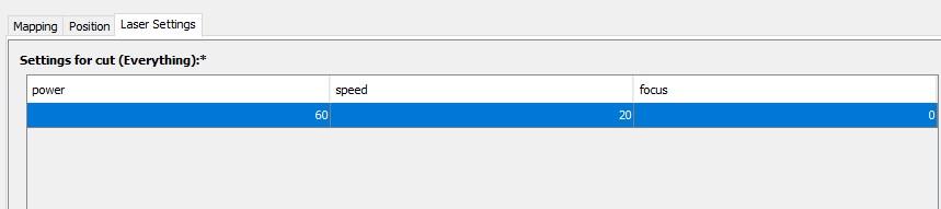
Make it readable for Visicut Software

The Results

Convert DXF to GCode

The software we use, to convert a dxf readable file to Gcode, is Visicut.

It is quite simple to use, just be aware of the few traps lying in wait for the newcomer.

One of these is, that you require the settings for the lasercutter

You can use GitKraken to generate you're RSA Key

Import you're lasercutter settings into VIsicut

You can use GitKraken to generate you're RSA Key

Open the dfx file

You can use GitKraken to generate you're RSA Key

define the cutting parameters

You can use GitKraken to generate you're RSA Key

decide where you want to start with cutting. I choose the 0 position

You can use GitKraken to generate you're RSA Key

Define the laser settings

You can use GitKraken to generate you're RSA Key

Export you're file to Gcode

You can use GitKraken to generate you're RSA Key

Manually enter the filename with de .gcode extension (Trap 2, dont forget to add the extension)

Octoprint

The Octoprintsoftware is a web interface for 3D printing, milling and lasercutters.

You upload the gcode file into the web interface, once you have navigated to the octoprint page.

\ You can use GitKraken to generate you're RSA Key

Not my screenshot, but this is the layout of octoprint

Once selected to print, you're pf kit is ready to be cut.

My press-fit kit came out pretty good, I mean I am able to kind of make a tank out of it

You can use GitKraken to generate you're RSA Key

Playing around with the kit


And If I play around a bit more a tank and a spherical construct can be made

You can use GitKraken to generate you're RSA Key

Pretty decent

Vinyl Cutting

Testing the Vinyl cutter

Lasercutter Walktrough

Brother CM 600

For the vinyl cuuter we used the Brother CM 600.

For the process of using th vinyl cutter, I used Canvas Workspcae by Brother. URL

I did not download the software and instead I created an account.

I used, Inkscape to draw 3 simple triangles (which were looking very similar to a well known force) for testing the vinyl cutter.

For testing the vinyl cutter, I used a plain paper A4 sheet. I wanted to know how wel it would cut sharp corners, because the design I had in mind has a lot of those.

Design

Tri-force design in canvasworkspace


This is the result of the plain paper.

A4 test

Kind of meh


My edit of existing design

I used and existing design, which I will edit to create a vinyl sticker.

You can Download the file here

I used Inkscape to trace the image and cleaned up any bit, that would be detremental to the cutting process.


A4 test

Select Trace Bitmap under the Path tool.


A4 test

Select the object, you want traced and select OK.


A4 test

Select the traced object and move the original in order to delete it.


A4 test

Remove left overs


A4 test

Save the altered image as SVG


Brother CM600 Workflow

As I said earlier the cutter has a software suite, called CanvasWorkspace. There is a dekstop version for Windows and macOS.

For those interested in downloading the software, this is the URL: CanvasWorkspace

Linux users, can just create an account and use the web-app (My personal choice tbh). And the process is pretty straight forward.

A4 test

Canvasworkspace after logging in


After creating an account and logging in, this is the first web-screen, you are greeted with.

Select "New" and your canvas will be presented.

On the "toolbar" of the web-app you will see an SVG icon. This is where you can upload our svg file.

Import

Upload your SVG into CanvasWorkspace


Now we can edit our image in CanvasWorkscape. Keep in mind that you're canvas is a representation of the cutting mat. And in this case the Low Tack Adhesive Mat 12"x 12"
or 305mm x 305mm.

Import

Place the design according to the dimensions


Import

Download the FCM file ont your local machine.


Save it on a USB and bring the USB to the vinyl cutter.

Once the vinyl cutter recognises the USB, it will read your FCM files.

Import

Select Cut.


Import

The cutting time will be displayed.

My design took about 15 minutes to cut and this is the end result.

Import

Not bad, though I could have cleaned up the SVG a bit more in hindsight.


The FCM file can be Downloaded here.

Assignment Complete