Group assignment:


Send a message between two projects (assignments made by different students)

The group Assignment link can be found here: Week 14 Group Assignment

Individual assignment:


Design, Build, & Connect Wired/Wireless node(s) with network or bus addresses

One Board to control them all


For this weeks assignment, I was advised to create the FabDuino, based on Neil's design, in order to get started with networking & comms, but also to use it in my final project.

The FabDuino is based on The Fabkit.

For designing the board, I used the schematics, our instructor provided me with and also the libraries.

From here on I used KiCad to design the board

Connect the PCB to the AVR Interface of the programmer

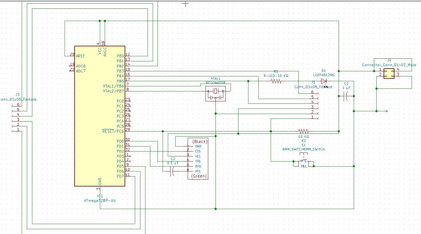
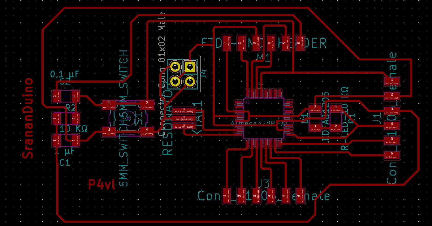
Schema of the SrananDuino Board.

Connect the PCB to the AVR Interface of the programmer

Routing the traces.

Connect the PCB to the AVR Interface of the programmer

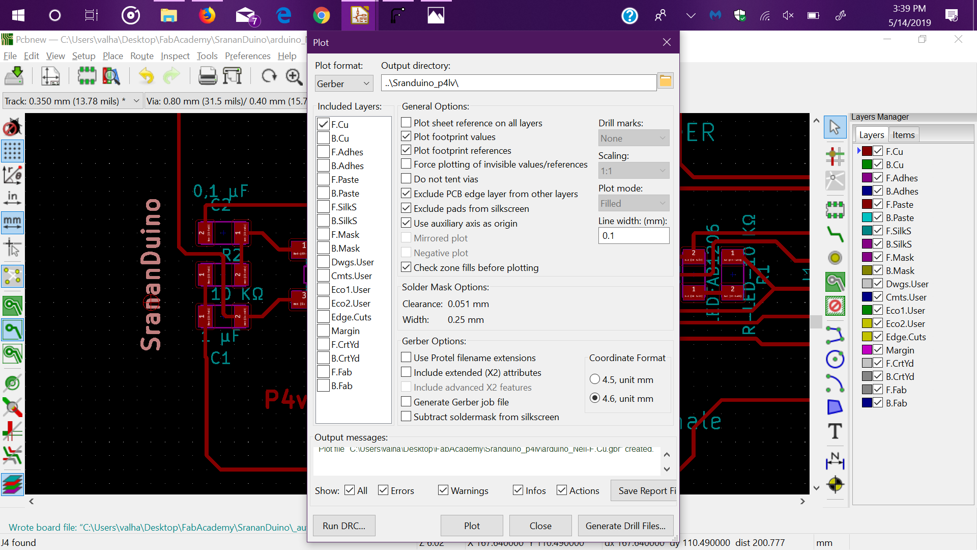
Generating the plot code.


For the milling of the board, I used the Stepcraft 340 and used the following parameters:

  • Cut Z: -0.15mm
  • Travel Z: 1.5mm
  • Feed Rate: 1 mm
  • Tool Diameter: 0.38mm
  • Spindle Speed: 2000 rpm/s
Connect the PCB to the AVR Interface of the programmer

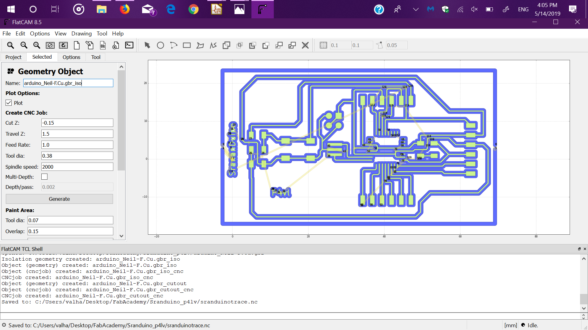
The CAM process of the Hello speaker board.


And for the cutout:

  • Cut Z: -1.5mm
  • Travel Z: 1.5mm
  • Feed Rate: 1 mm
  • Tool Diameter: 0.9 mm
  • Spindle Speed: 2000 rpm/s
  • Multi-Depth: True
  • Depth/Pass: 0.5mm
Connect the PCB to the AVR Interface of the programmer

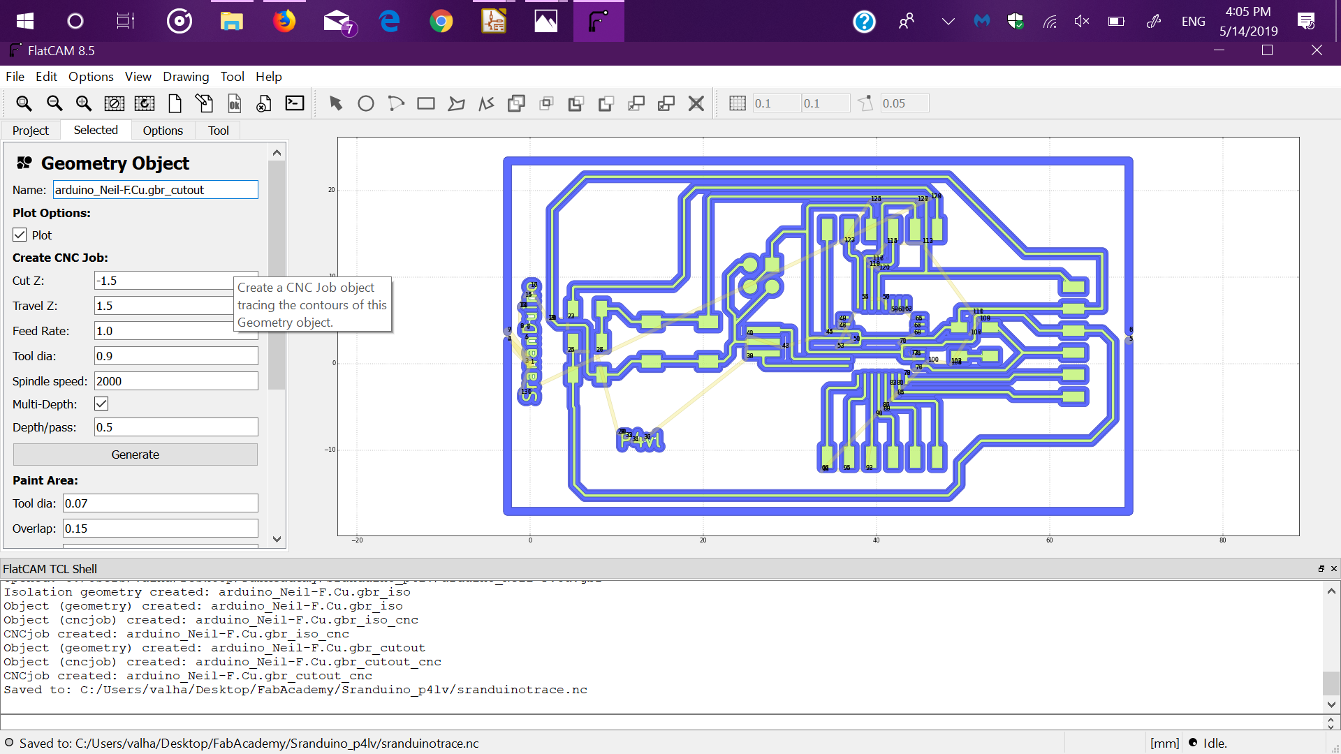
The CAM process of the SranaDuino PCB cutout.


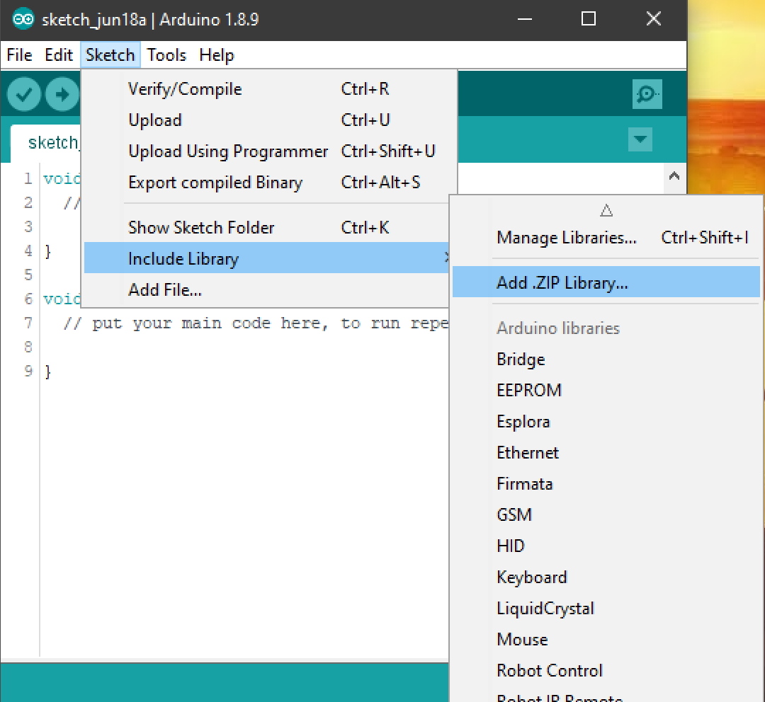
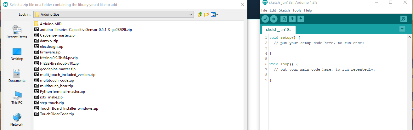
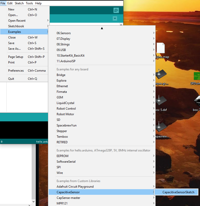
Programming the SrananDuino

After stuffing the board, I wanted to burn the bootloader and in order to do that, I had to edit the boards.txt of Arduino IDE.

On Windows this file is located at, C:\Program Files (x86)\Arduino\hardware\arduino\avr, mostly.

The boards.txt on Windows is write protected, which we have to change in order to edit the file.

On Windows the process to grant the "user" write privelages, is by right-clicking the file->porperties->click the Security tab, click on Edit grant the user write permission.
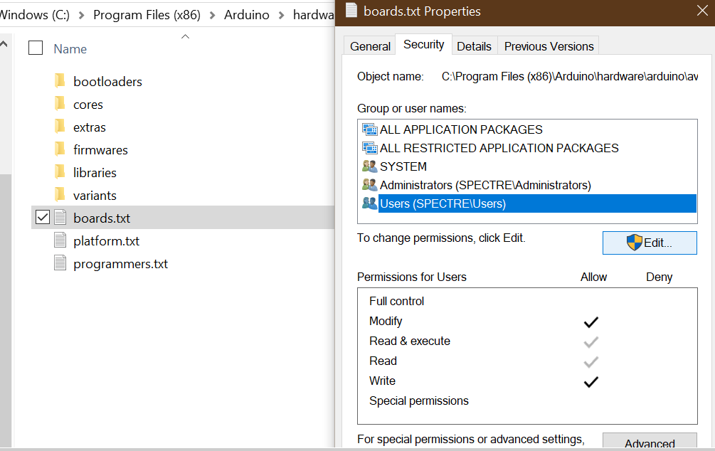
Connect the PCB to the AVR Interface of the programmer

You shall PASS!

Note: If you are using a PC, which is administrated by an organization or institution, please refer to your IT admin, for write privelages,

or download the stand-alone version of Arduino IDE.


hello.name=hello.arduino, ATmega328P, 5V, 8MHz internal oscillator
hello.upload.protocol=arduino
hello.upload.maximum_size=30720
hello.upload.speed=57600
hello.bootloader.low_fuses=0xE2
hello.bootloader.high_fuses=0xDA
hello.bootloader.extended_fuses=0x07
hello.bootloader.path=arduino:atmega
hello.bootloader.file=ATmegaBOOT_168_atmega328_pro_8MHz.hex
hello.bootloader.unlock_bits=0x3F
hello.bootloader.lock_bits=0x0F
hello.build.mcu=atmega328p
hello.build.f_cpu=8000000L
hello.build.core=arduino:arduino
hello.build.variant=arduino:standard
                                    

Added Lines:

##############################################################
hello.build.board=atmega328p


hello.upload.tool=arduino:avrdude
hello.bootloader.tool=arduino:avrdude
                                

Connect the PCB to the AVR Interface of the programmer

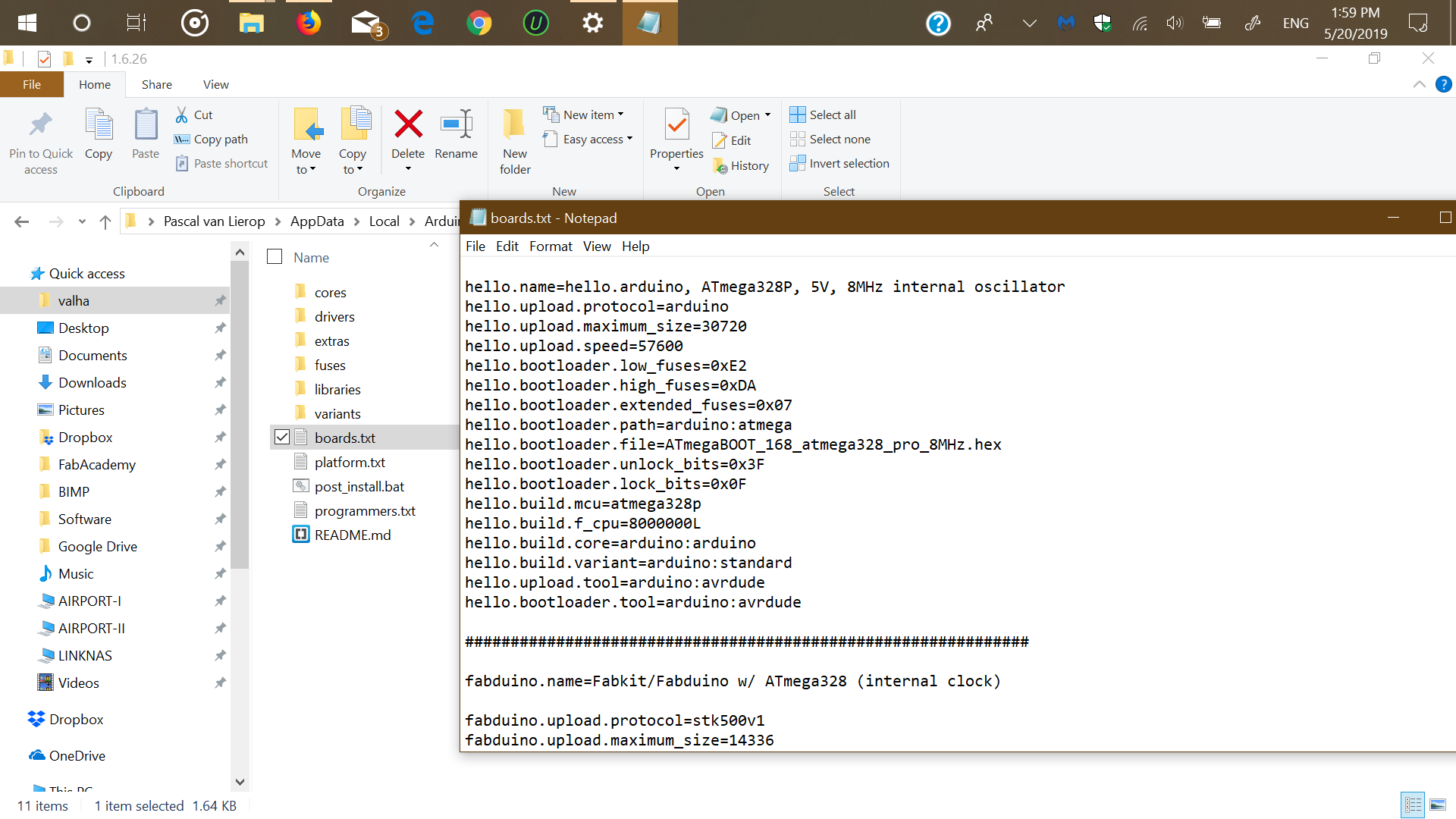
Editing the Arduino IDE boards.txt.


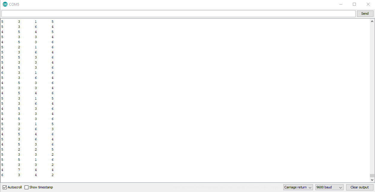
After saving the edit, I restarted Arduino IDE (just in case) and was able to burn the bootloader to my board, using the FabTinyUSB.

Burning the Bootloader

The SRduino KiCad project based on Neil's design:Download

The SRduino KiCad schematics:Download

The SRduino KiCad PCB:Download

Networking the boards.


Using Serial to communicate between the hello.load and SrananDuino.

Using the FTDI, I first loaded up the Serial Event sketch found in the Arduino examples, to get a better undestanding of the code.

After reading and undesrtanding the code, I altered it slightly (with the help of our instructor) to just print out a value and blink the led on the SRDuino by adding a

variable. The function of this x variable is to print only numbers bigger than 2 and flashing the LED once the correct data has been recieved.

So x = inputString.toINt(); if (x >2) will make sure that no serial data will be printed nor the LED to be flashed if the value entered is smaller than 2.

Below is the few lines added to the serialevent sketch.

x = inputString.toInt();
if (x > 2){
digitalWrite(LED_BUILTIN, HIGH);   // turn the LED on (HIGH is the voltage level)
delay(1000);                       // wait for a second
digitalWrite(LED_BUILTIN, LOW);    // turn the LED off by making the voltage LOW
delay(1000);                       // wait for a second
    }
}
                            

I then hacked the code, for communications between my input week board and the SRDuino. Every time the touchpad senses a change in pressure, the board will transmit the data,

via serial, to the SRDuino. The SrDuino will then flash it's LED, if data is recieved.

The Arduino ino file:Download


Getting ready for sending capacitive touch through serial

I wanted to get started with sending the registered data right away!

The data the SRDuino collects from the touch sensor needs to be converted into readable data for MIDI or WAV.

At first I wanted it to inteface and communicate with software such as FL studio/ Ableton live and the likes, but our instructor advised to try Processing first, as this is also the assignment for Week 16

I started with amazing tutroials from Jeremy Blum: Arduino + Processing, in order to get aquinted with the new IDE (which surpisingly Arduino is based off of).

After this tutorial, also looked at the sketches Processing 3 comes with.

Loading the capsense lib into Arduino IDE, was first required. The library can be found here:Capacitive Sensing Library

The demo/tutorial sketch it comes with also provides serial write.

After downloading the library .zip, add it via Sketch->Include Library->Add.Zip Library


Navigate to the zip file and select.


Load up the CapacitiveSensor sketch.

Cap sensors untouched


Cap sensors touched.


Now to make this communicate to processing

I loaded up the tutorial sketch and made it read the serial data defined in arduino ide. It would not read right away, so after some brainstorming with my instructor, he sugested to use the map function.

And to use 1 pin and build from there.

This tutorial is a great starting point: Map Function

With the map function ready, I was able to read the serial data in Processing 3.

It is a simple serial read program, which can be found in the examples.

It would read a change coming form the serial, but it changed withut me touchin the sensor. And after fighting with it a bit, I decide to get some search engine help.

I came across a github user by the name of joselynNeon and found this difference in the code:

Mine: mapped = map(total1, 0, 1023, 0, 255); Serial.println(mapped);

joselynNeon's: long mapCap = map(CapSense1, 0, 900, 0, 10); Serial.print(mapCap, DEC);Serial.print(",");

Can you spot the difference? I was using values made for analog (due to the tutorial) instead of lowering the values. This creates inconsistencies in the sensors.

Cap sensors untouched.

Cap sensors touched.

Lesson learned.

The Arduino ino file:Download