Group Assignment

Measure the analog levels and digital signals in an input device.


The group Assignment link can be found here: Week 11 Group Assignment

Individual Assignment

Measure something. add a sensor to a microcontroller board that you have designed and read it.


Making the Hello.txrx board.

For my project, I might try a strumpad to at least emulate the playing of strings and or palm muting the strings

The step response board, might help me in learning the process of it all.

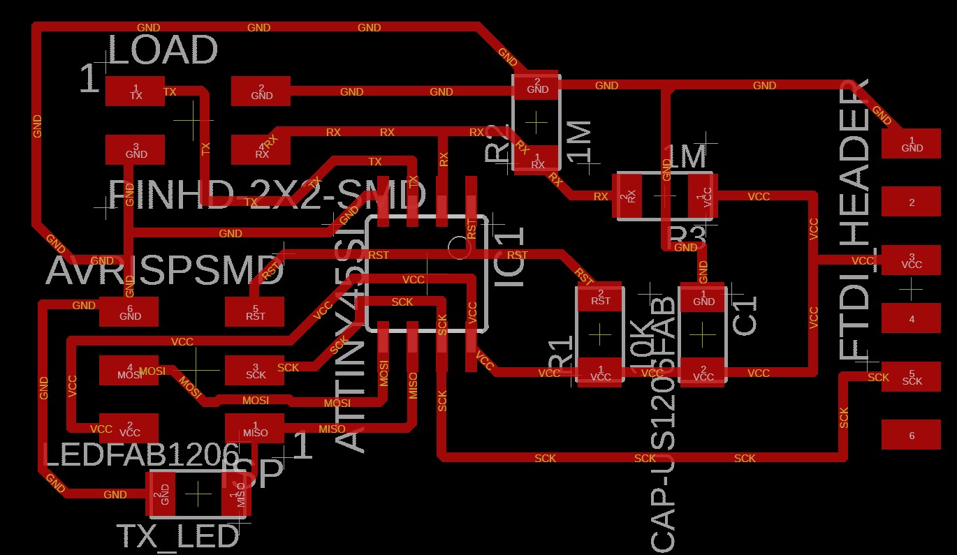
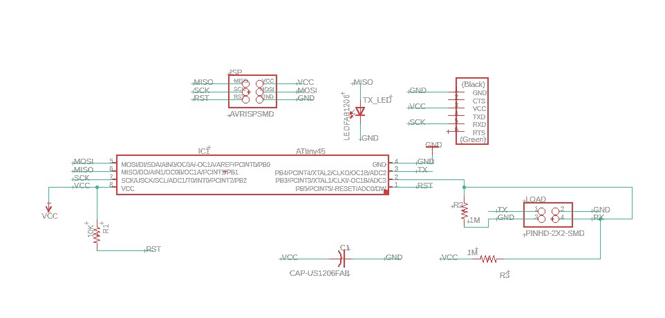
I took to redrawing Neil's txrx board with the ATTiny 45.
Connect the PCB to the AVR Interface of the programmer

The Schematics of the Hello board.

Connect the PCB to the AVR Interface of the programmer

The PCB layout of the Hello board.


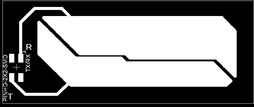
After I redrew Niel's hello board I made the pad in eagle as well, using the polygon feature. Still quite new to this workflow, but still came out rather well
Connect the PCB to the AVR Interface of the programmer

The TxRx pad.


I used Flatcam to create the gcode for the mill with the following settings:

  • Cut Z: -0.15mm
  • Travel Z: 1.2mm
  • Feedrate: 60mm/min
  • Tool Diameter: 0.4mm
  • Spindle Speed: 7000 RPM

Connect the PCB to the AVR Interface of the programmer

Generating the trace of the Hello board.


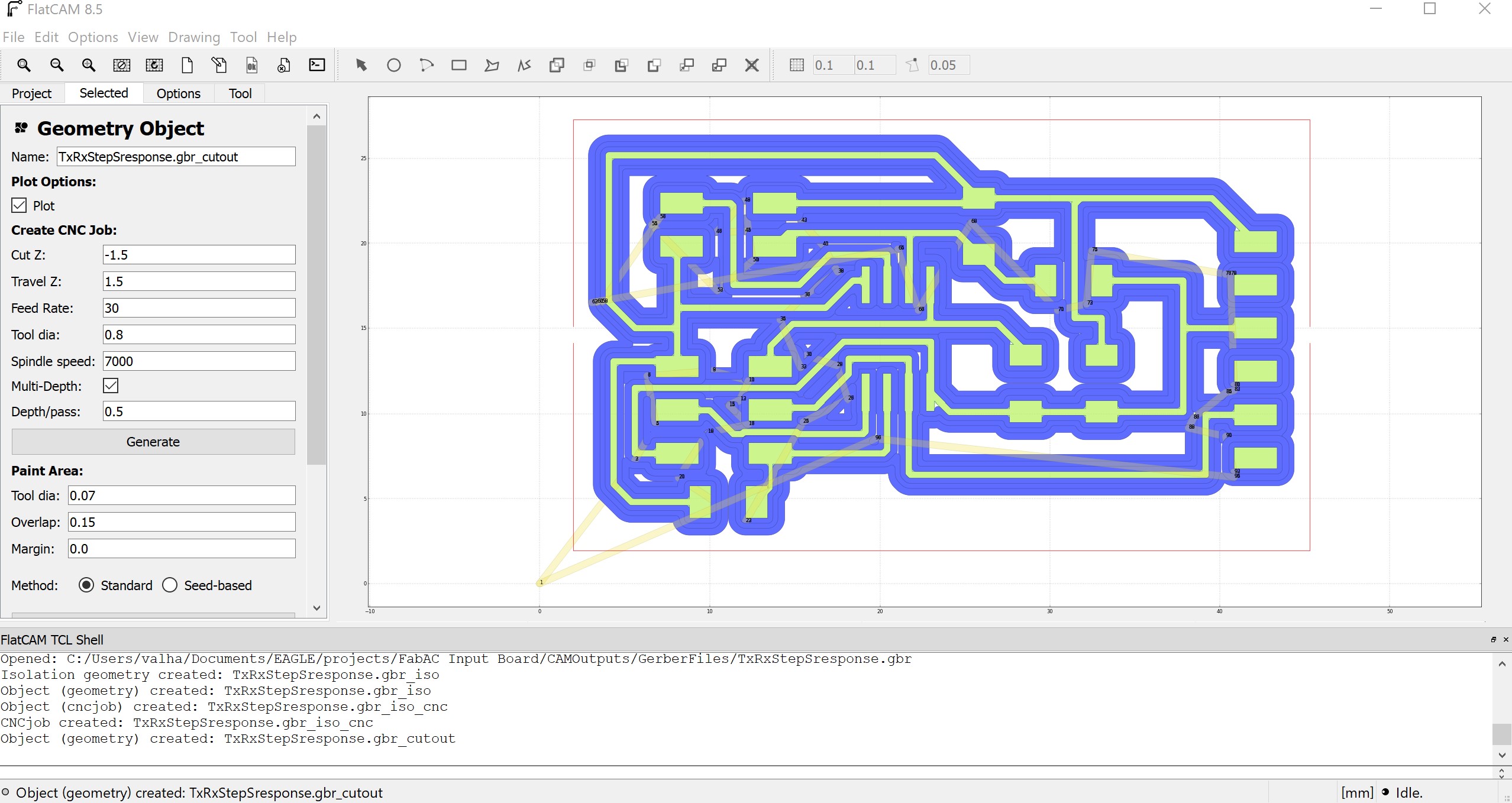
For the cutout I used the following settings:

  • Cut Z: -1.6mm
  • Travel Z: 1.5mm
  • Feedrate: 30mm/min
  • Tool Diameter: 0.8mm
  • Spindle Speed: 7000 RPM

Connect the PCB to the AVR Interface of the programmer

Generating the cutout of the Hello board.


For the TxRx pad, I used the same settings.
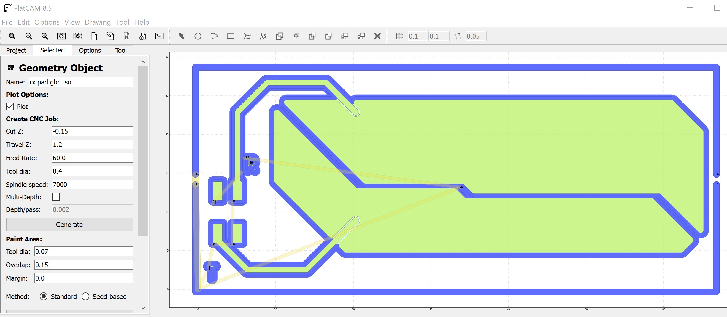
Connect the PCB to the AVR Interface of the programmer

Generating the traces of the TxRx pad.
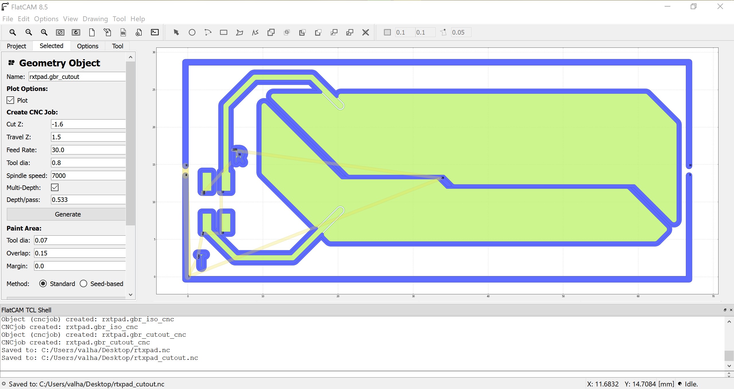
Connect the PCB to the AVR Interface of the programmer

Generating the cutout of the TxRx pad.

Milling the Board

For this process, I used candleCAM, which uses GRBL to communicate to the mill.

Candle is quite neat, as you can use the software to create a heightmap of the cu plate.
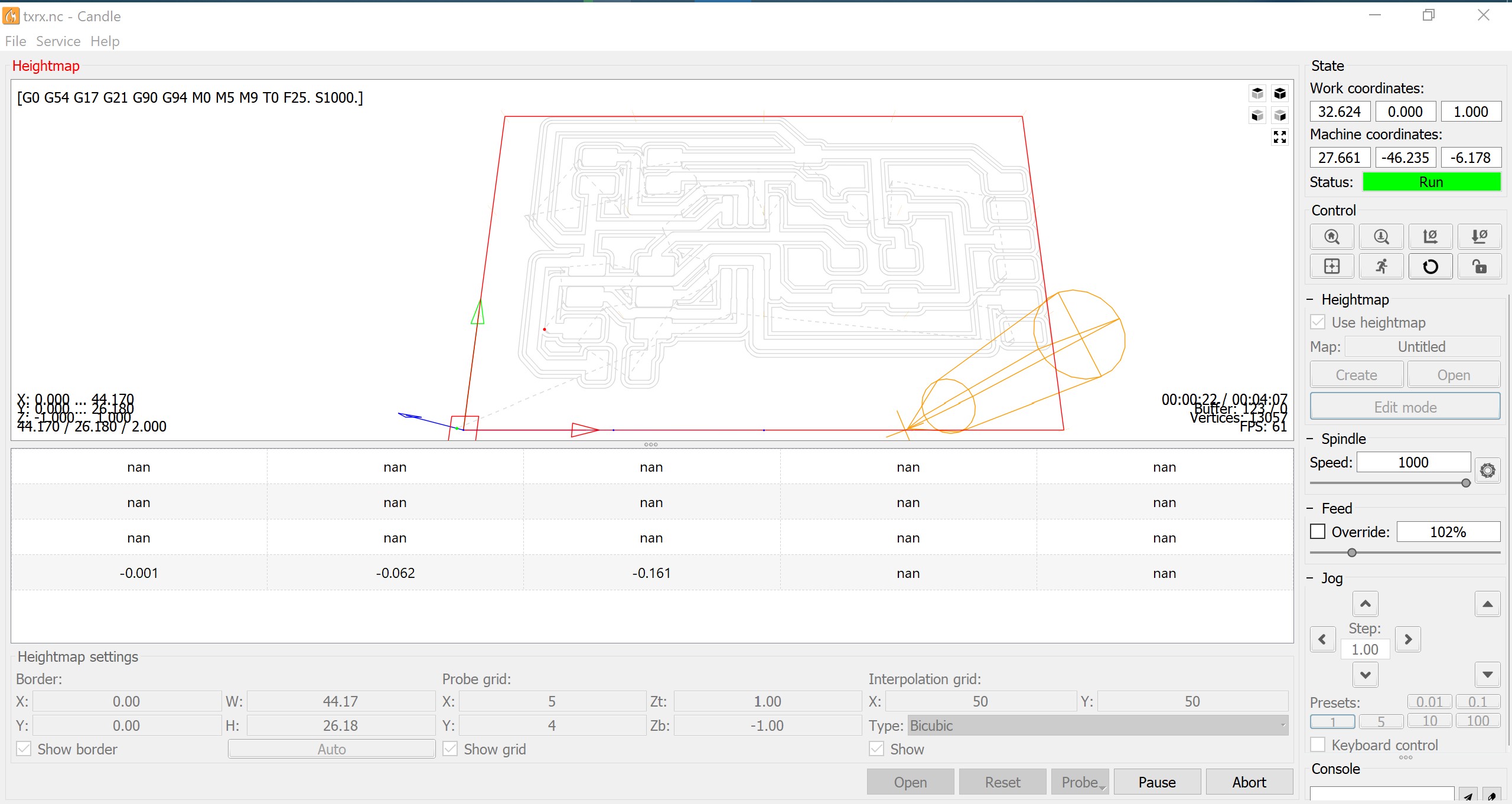
Connect the PCB to the AVR Interface of the programmer

Generating the heightmap.


The heightmap can be used for all jobs, if you want, but I am using it just for this cu plate.

The same process for the pad.
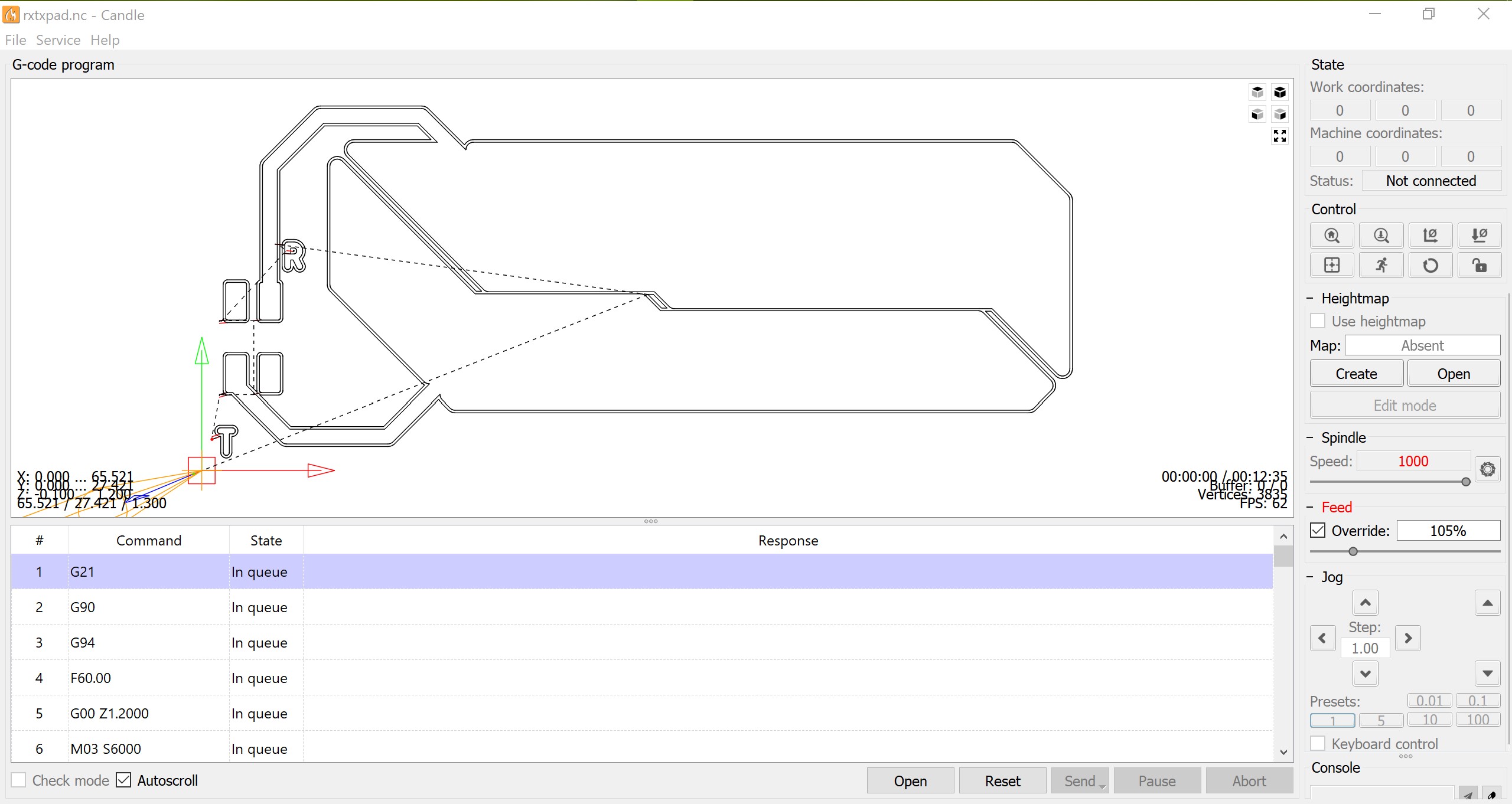
Connect the PCB to the AVR Interface of the programmer

Milling the TxRx pad using Candle software.

Connect the PCB to the AVR Interface of the programmer

Milling the TxRx pad using Candle software.
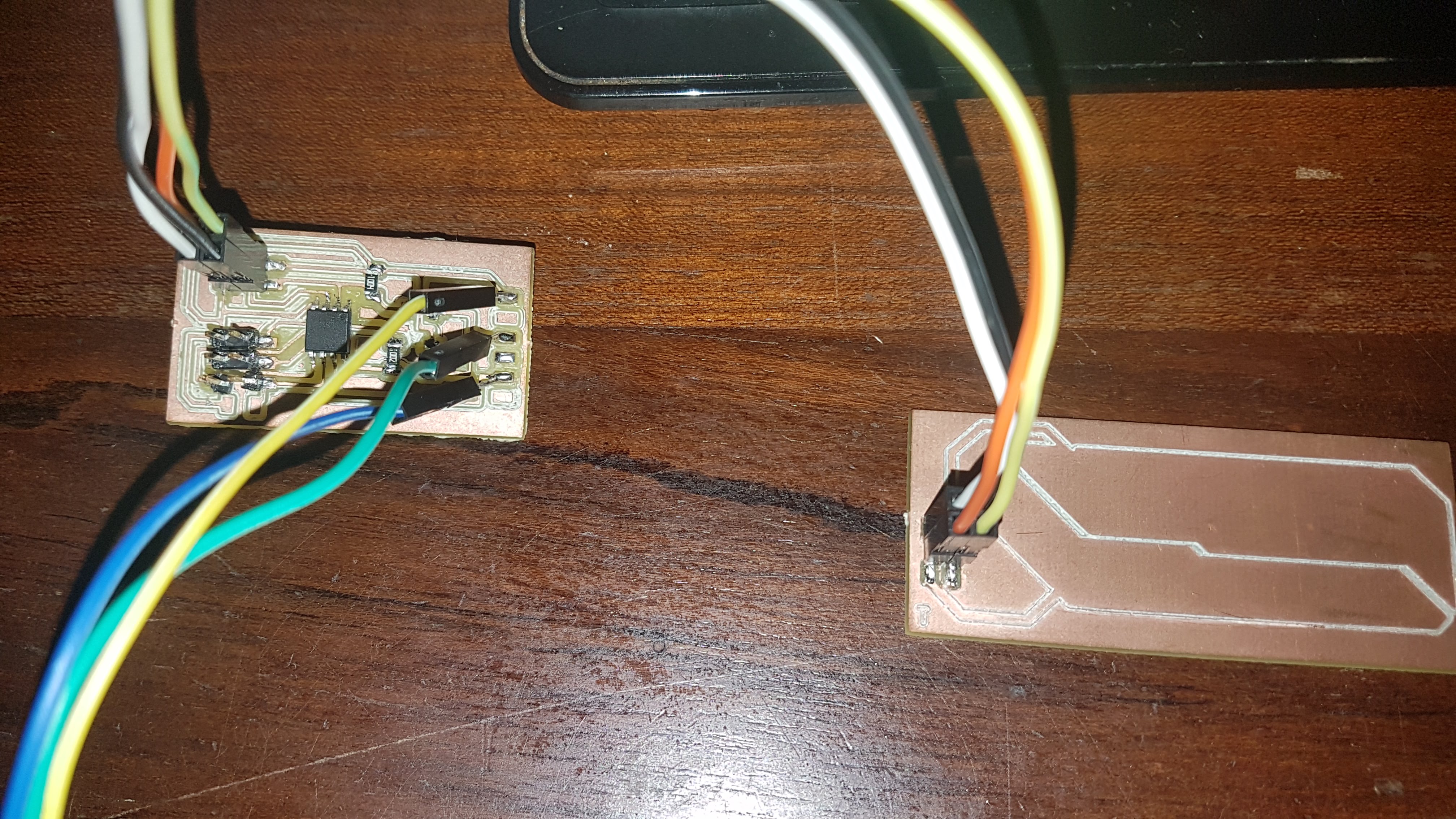
Programming the board


Using Neil's hello.txrx code

After stuffing the board, I burnt the bootloader with my FabTinyISP and loaded up Neil's hello.txrx.45.c code

Connect the PCB to the AVR Interface of the programmer

About to burn the bootloader


Running into Trouble

After loading up the C code, I proceeded to run the Python code, but it just crashed right away

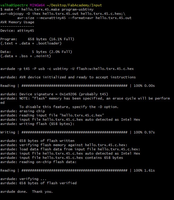
Leave it up to me, to go looking too far for a solution, but I first thought it might not have loaded the C code correctly. I loaded the make file with Bash shell and tried again.

Connect the PCB to the AVR Interface of the programmer

Loaded up the C code via makefile


The .py program was still crashing. So now I was getting the gist of it. Never assume it will work out of the box, always double check is the learning process.

I opened the .py file with the IDLE editor Python for Windows comes with and looked at the code.

It seemed I was running the code with Python 3 and not Python 2.

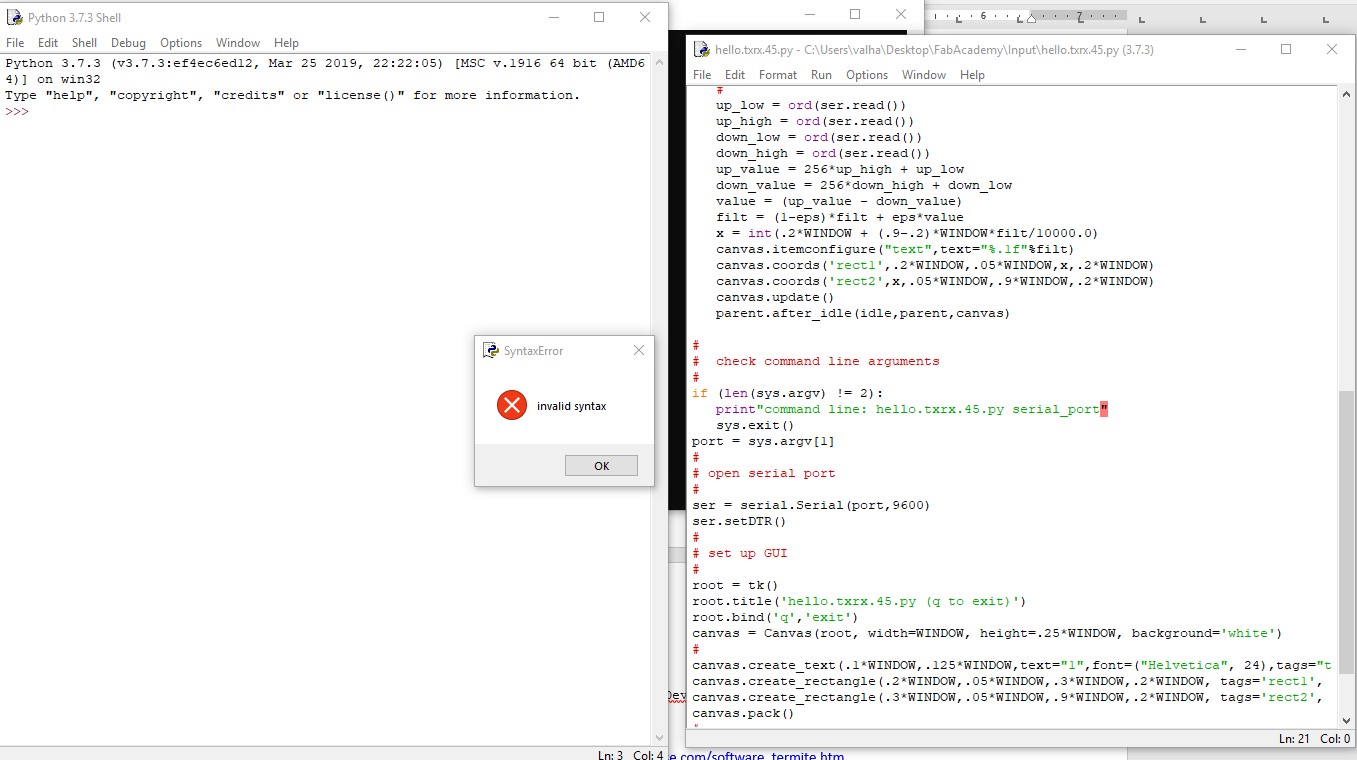
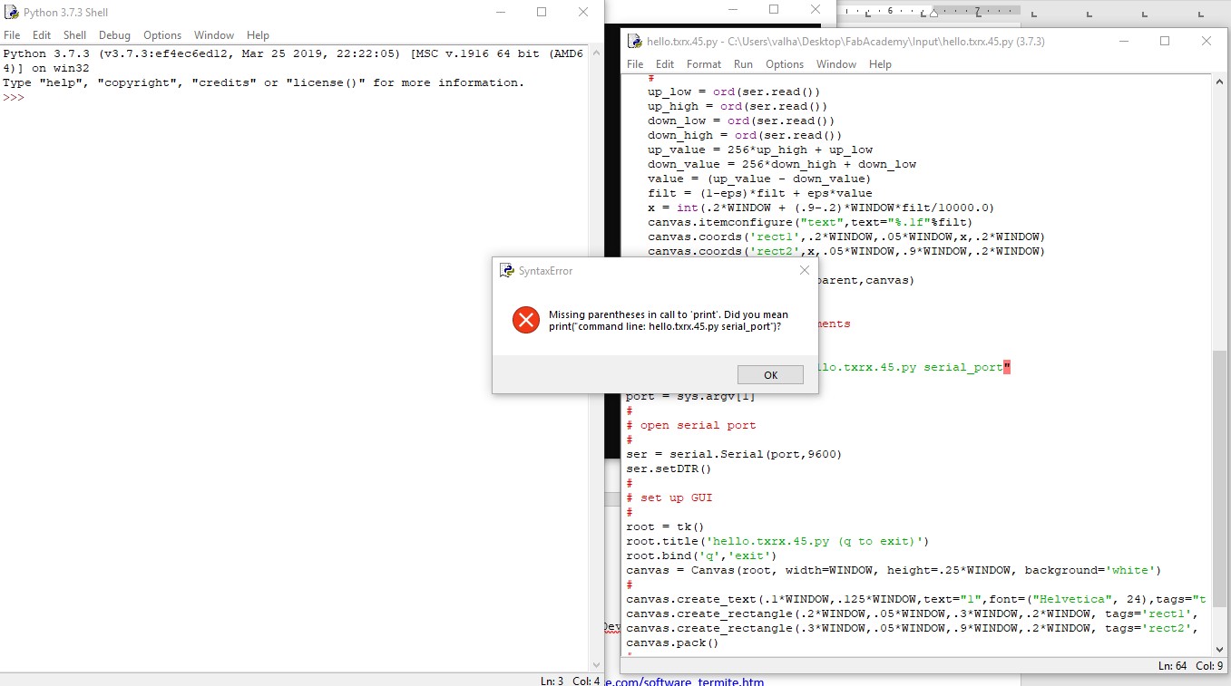
So I tried making the code compatible to Python 3 and found some invalid syntaxes ( of course Python 2 will run it just fine)

The invalid syntax

The invalid syntax

Connect the PCB to the AVR Interface of the programmer

Yup missing parantheses for Py 3.


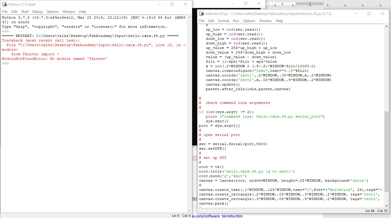
The next error I recieved is one stating that the TKinter module was none existent. Python 3 changed this from Tkinter to tkinter.

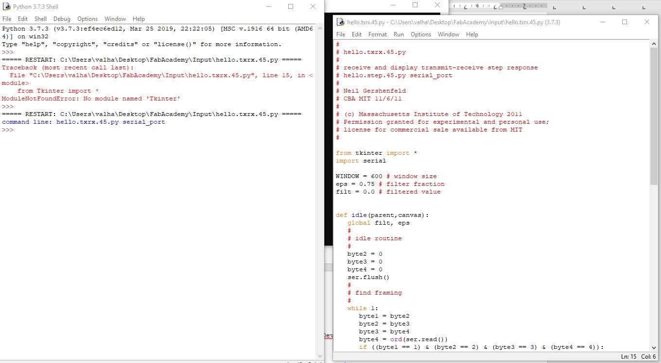
After swapping the T with t, the code seemed to run fine, but I was not receiving any GUI.

Connect the PCB to the AVR Interface of the programmer

TKinter module missing? nope. Change TK to tk for Py 3

Connect the PCB to the AVR Interface of the programmer

Program should run fine now.


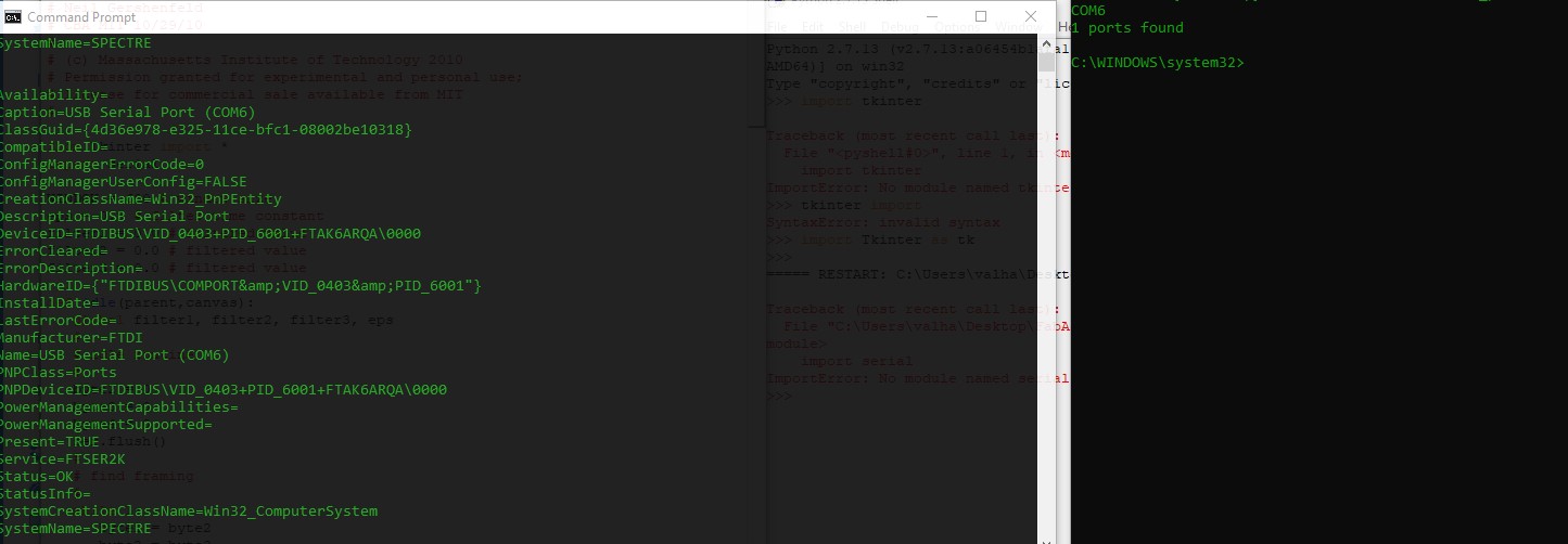
In Windows, one cannot simply check USB connections with lsusb, no we have to enter : "wmic path CIM_LogicalDevice where "Description like 'USB Serial%'" get /value" in order to see the USB connections.

And as reference I used the python -m serial.tools.list_ports

Connect the PCB to the AVR Interface of the programmer

Verifying if the serial was being read correctly

Starting Fresh

For some reason, I wanted to begin fresh, because I was testing the waters with Jetbrain's Pycharm, Anaconda etc.

Uninstalled all Python related sofware, cleaned Registery and any remaining folders and reinstalled Python 3 & with 2 for easy switching.

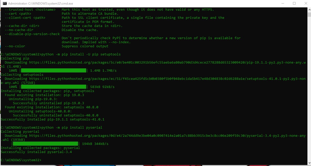
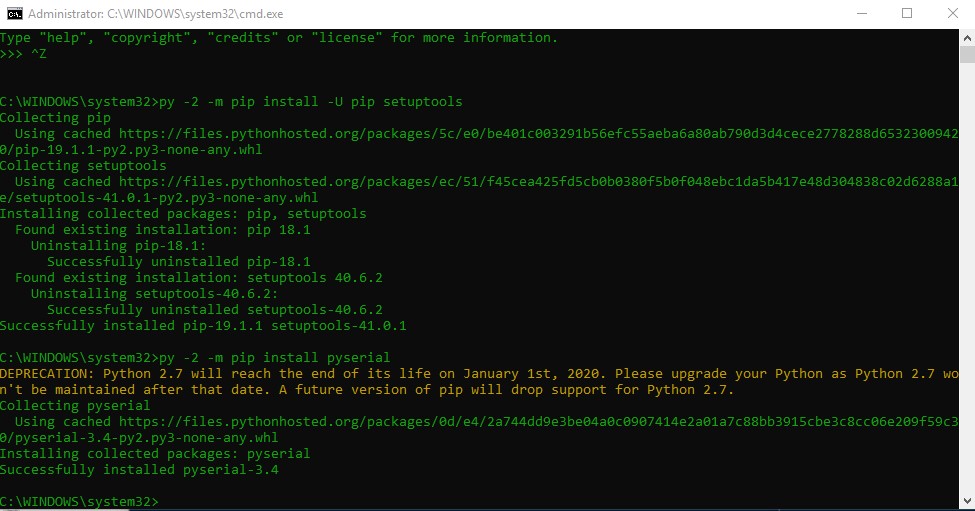
Installed the Pyserial and Pip tools.

Connect the PCB to the AVR Interface of the programmer

For Py V3 just install Python for Windows

Connect the PCB to the AVR Interface of the programmer

Define PythonV2 with py -2

For sanity's sake I edited the py program once again for Pyhton2 and still no luck, SO i decided to run the py program via the command line.

Lo and behold it worked ( after I defined the port ) with py -2 txrx.py in the same directory as the python file.

Downloads

TxRx Schematics Download

TxRx Board Download

TxRx Traces Download

TxRx board cutoutDownload

RxTx PadsDownload

RxTx Pad CutoutDownload