Week 12 Output devices
This week we had group assignment and an individula assignment
Group assignment
For the group assignment we had to measure the power consumption of an output device. For more information about the individual assigment click here.
Individual assignment
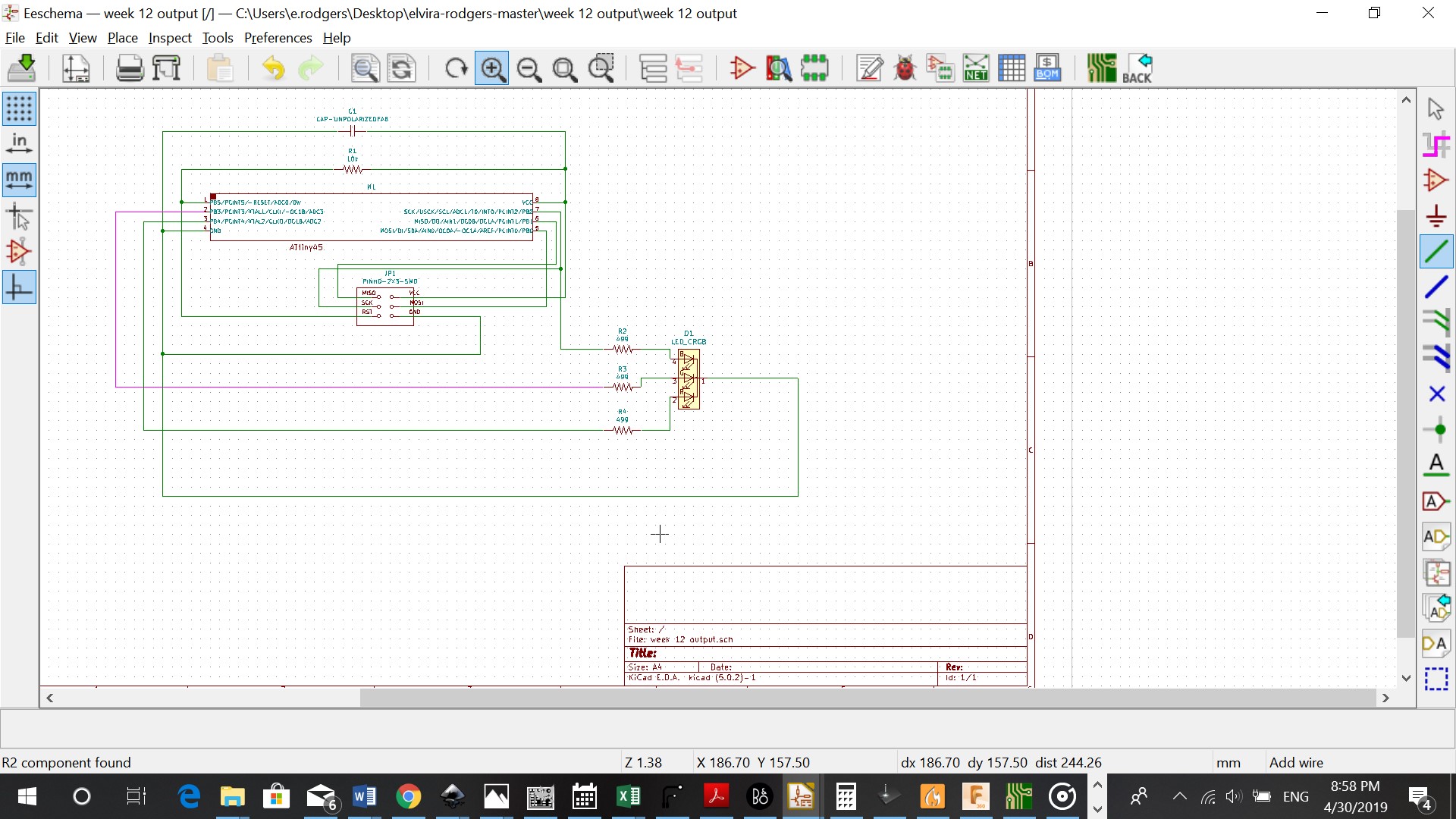
For the individual assignment we add an output device to a microcontroller board you’ve designed, and program it to do something. I used the Led relay board on the fabacademy site but instead of 15 LED, I made a schematic in Kicad with 4 multicolored LED’s.
Designing
The components that I used for this assignment are:
-
Capacitators (1)
-
Resistors 10K (1), 499 (3)
-
RGB led (multicolored)
-
Attiny45 microcontroller
-
AVRISPSMD, 2x3 header
Just like week 11 I followed the same steps to make the schematics for the board and generate it.
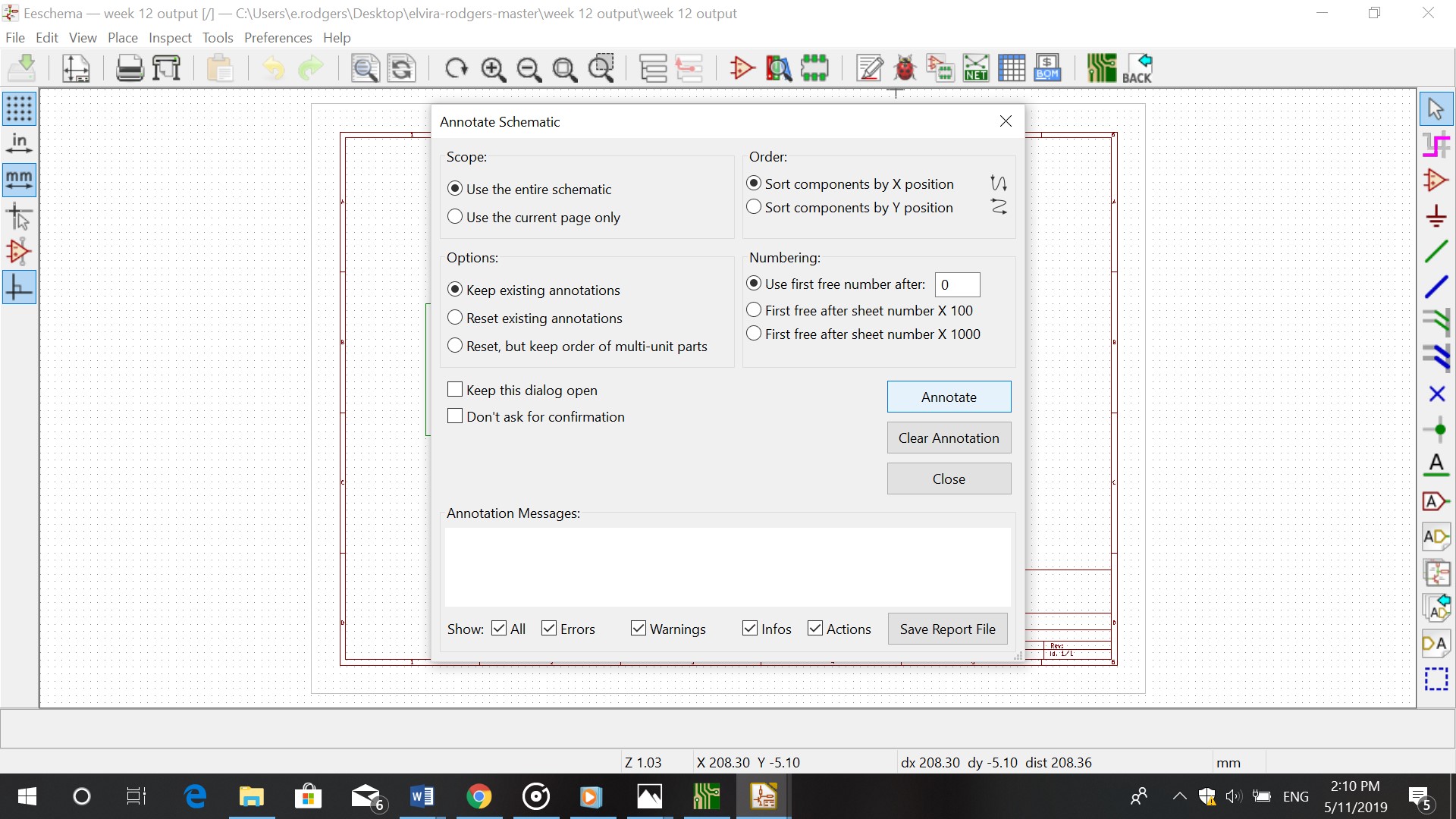
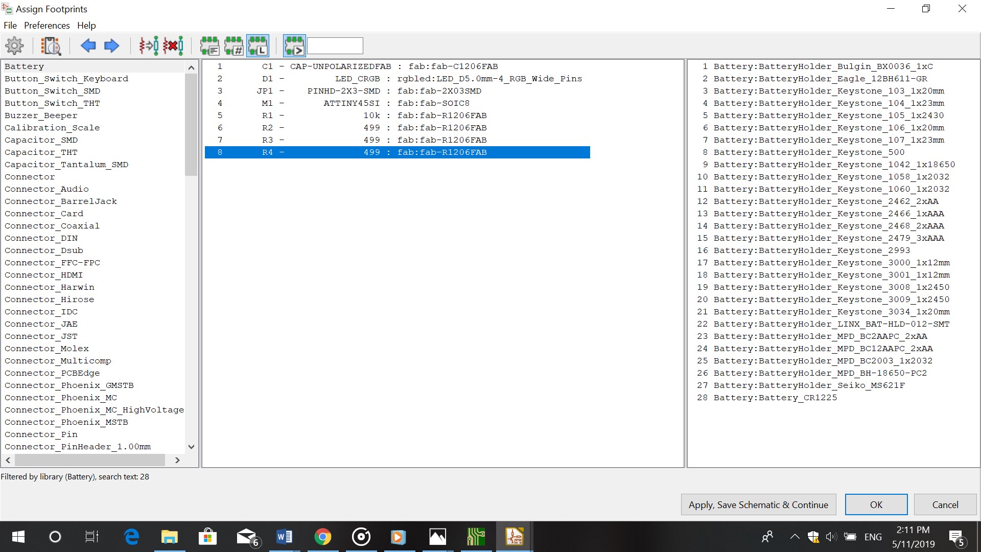
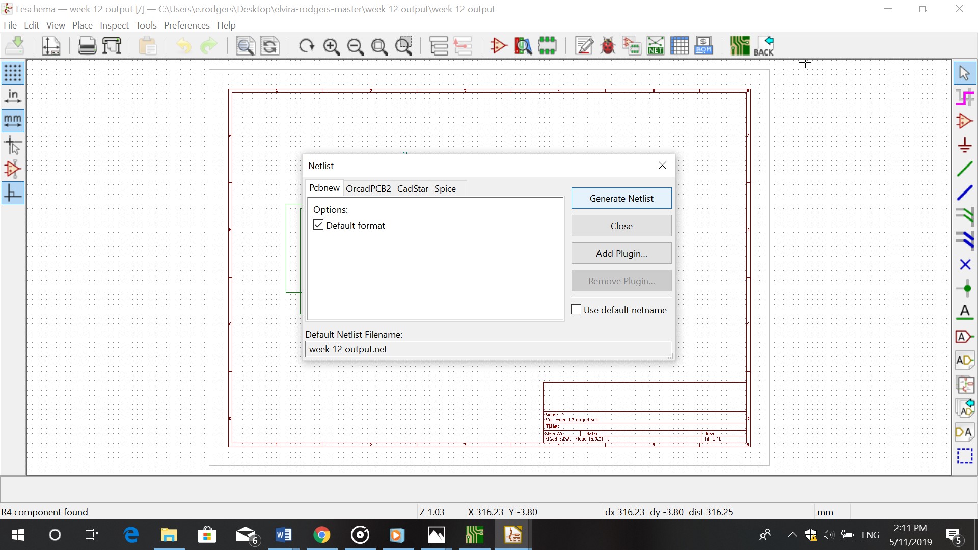
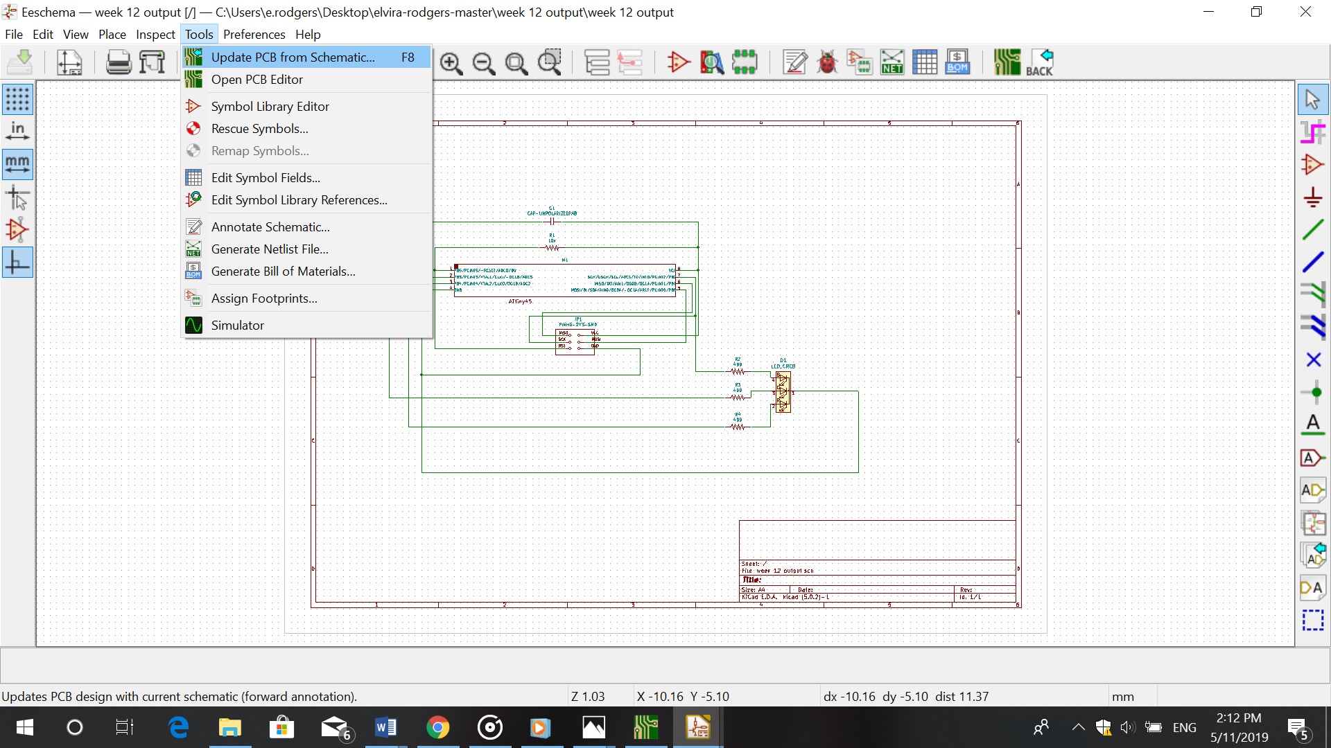

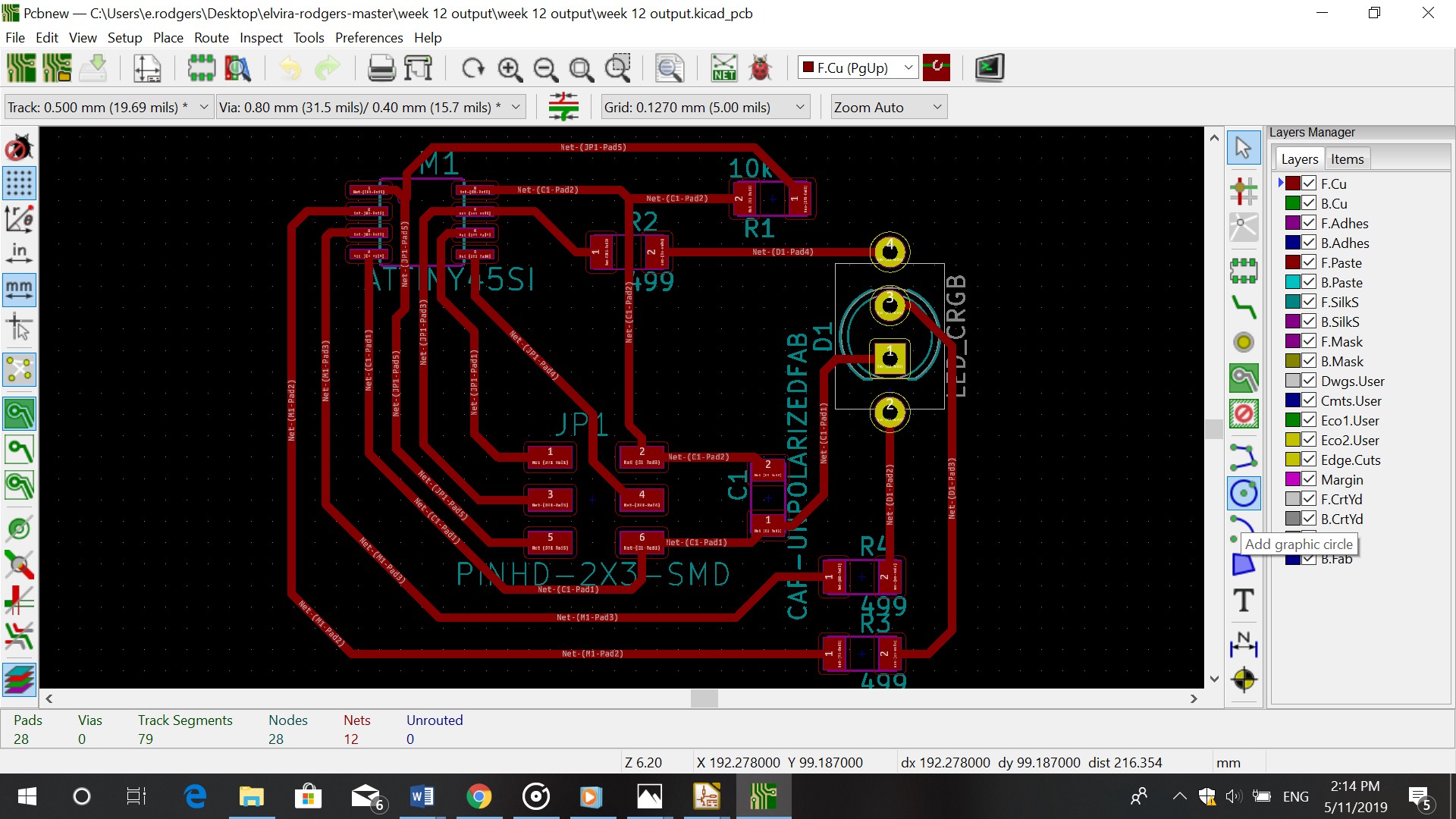
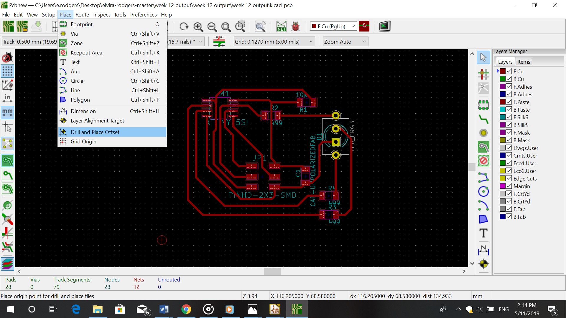
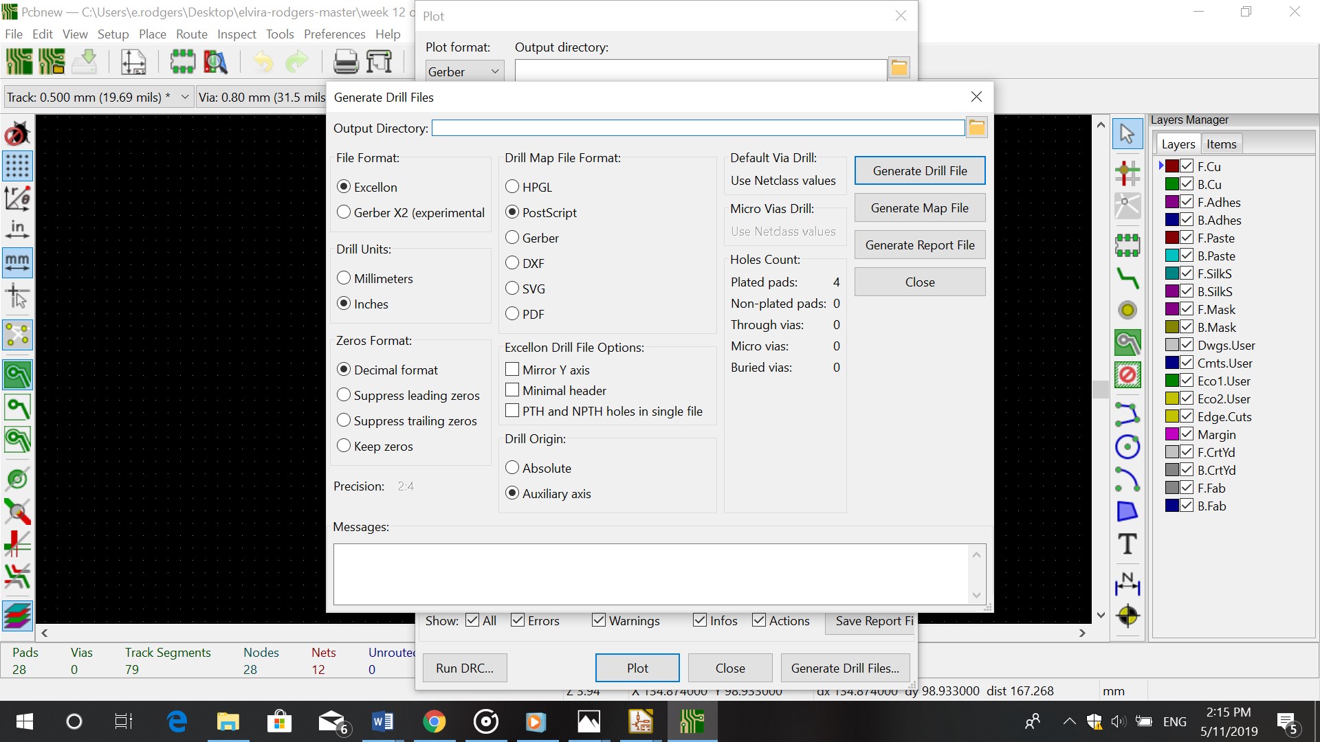
After applying the schematic I put in the tracks. Set the drill ofset and plotted the schematic.
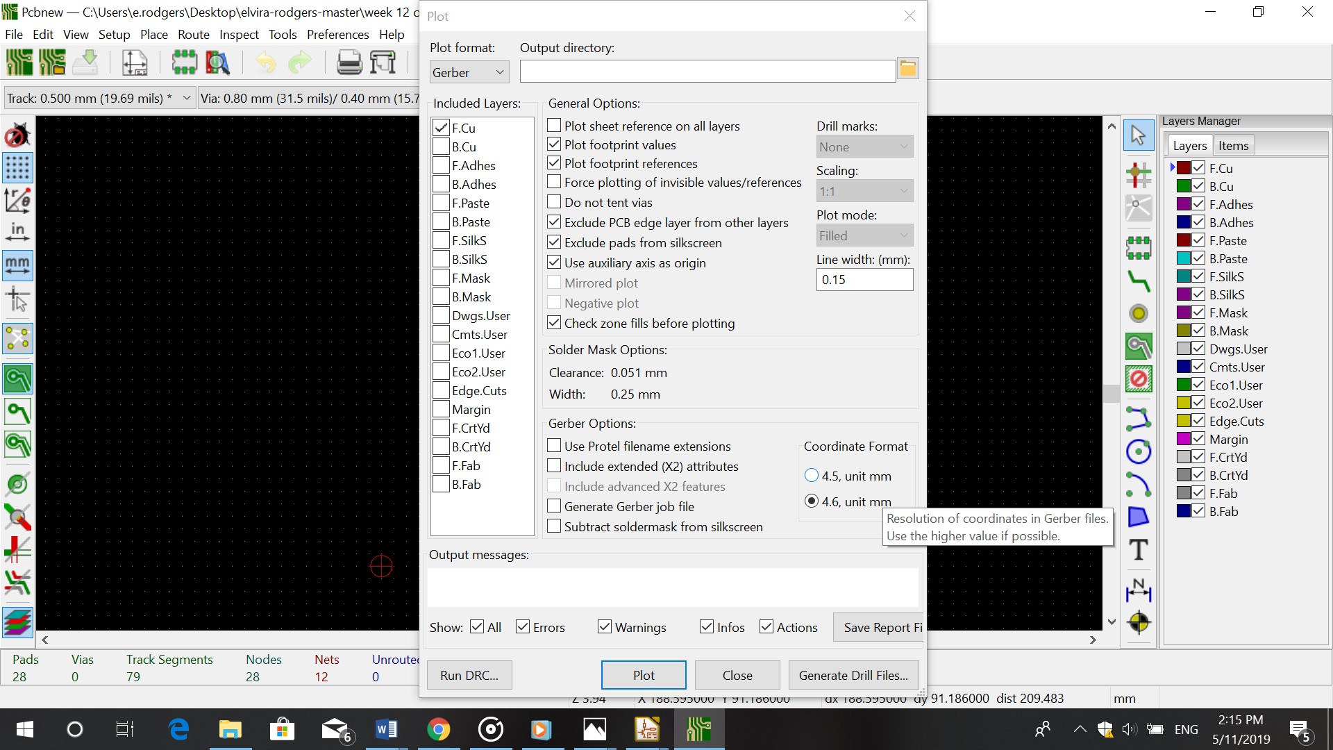
Flatcam
Tracks
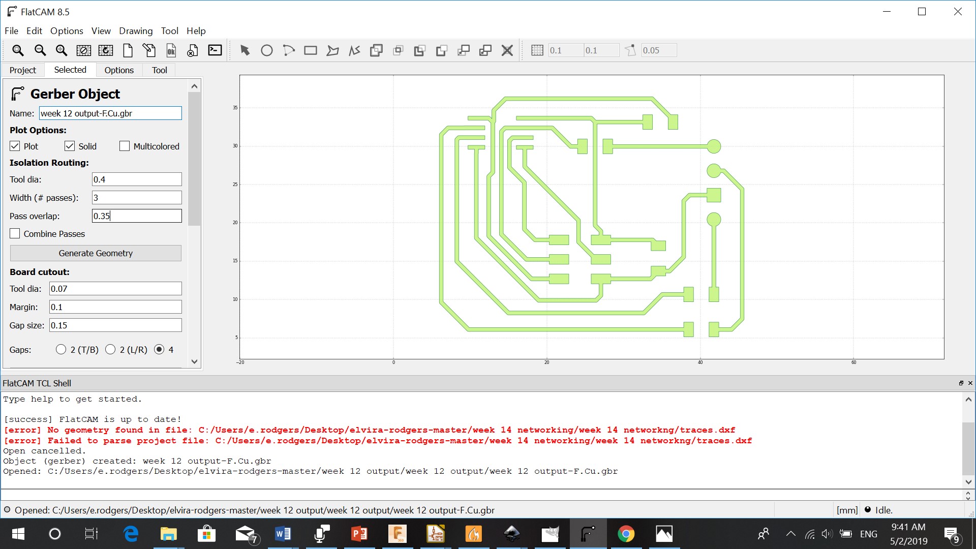
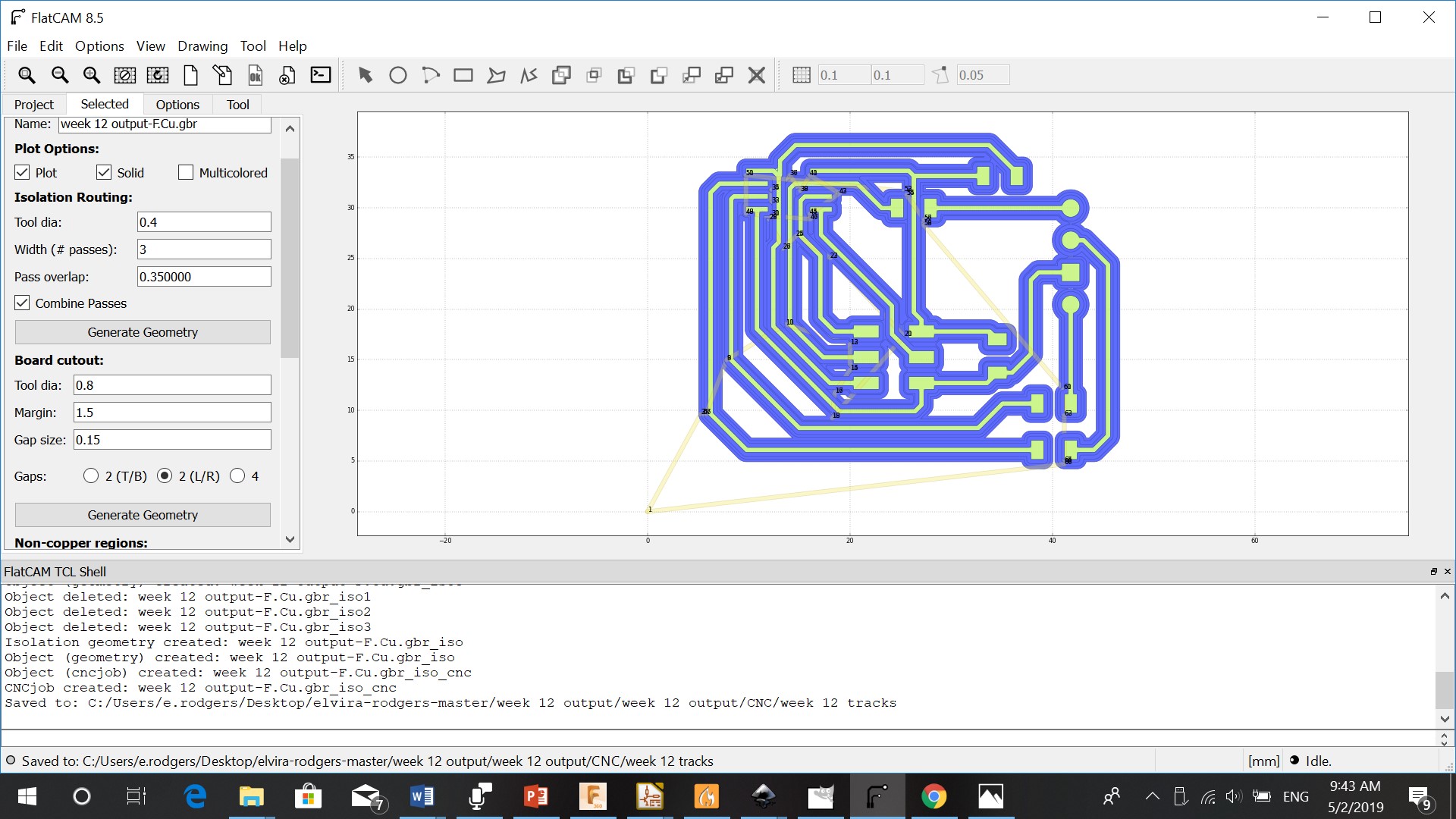
I opened the Gerber file in FlatCam (the one ending with F.Cu.gbr)
In project I double clicked on the name of the Gerber file and set the parameters
Tooldiameter: 0.4 mm
Width: 3
Passes overlap: 0.35
I then generated the Geometry
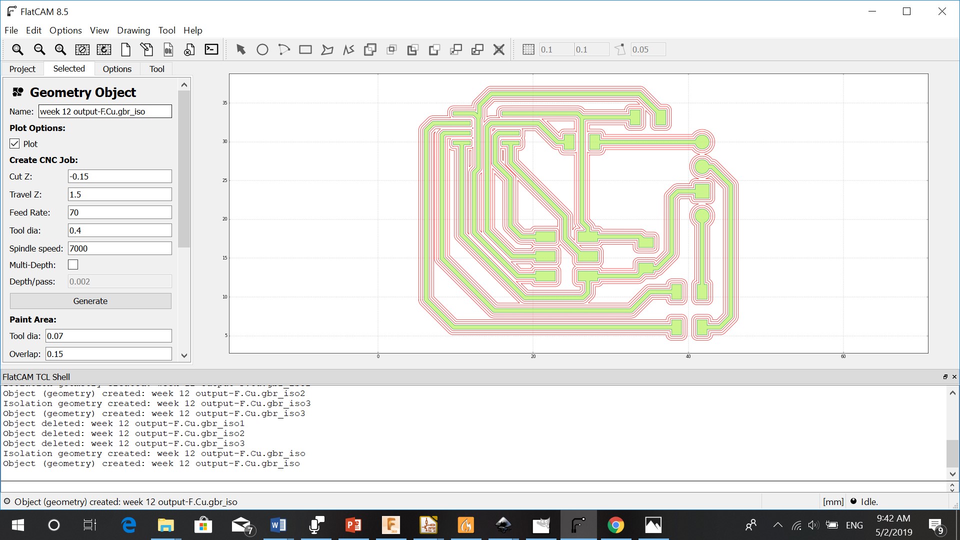
I went to project again and clicked on the file ending with _iso
The parameters that I used are:
Cut Z: - 0.15
Travel Z: 1.5
Feedrate: 70
Tooldiameter: 0.4
Spindle: 7000
I generated the file
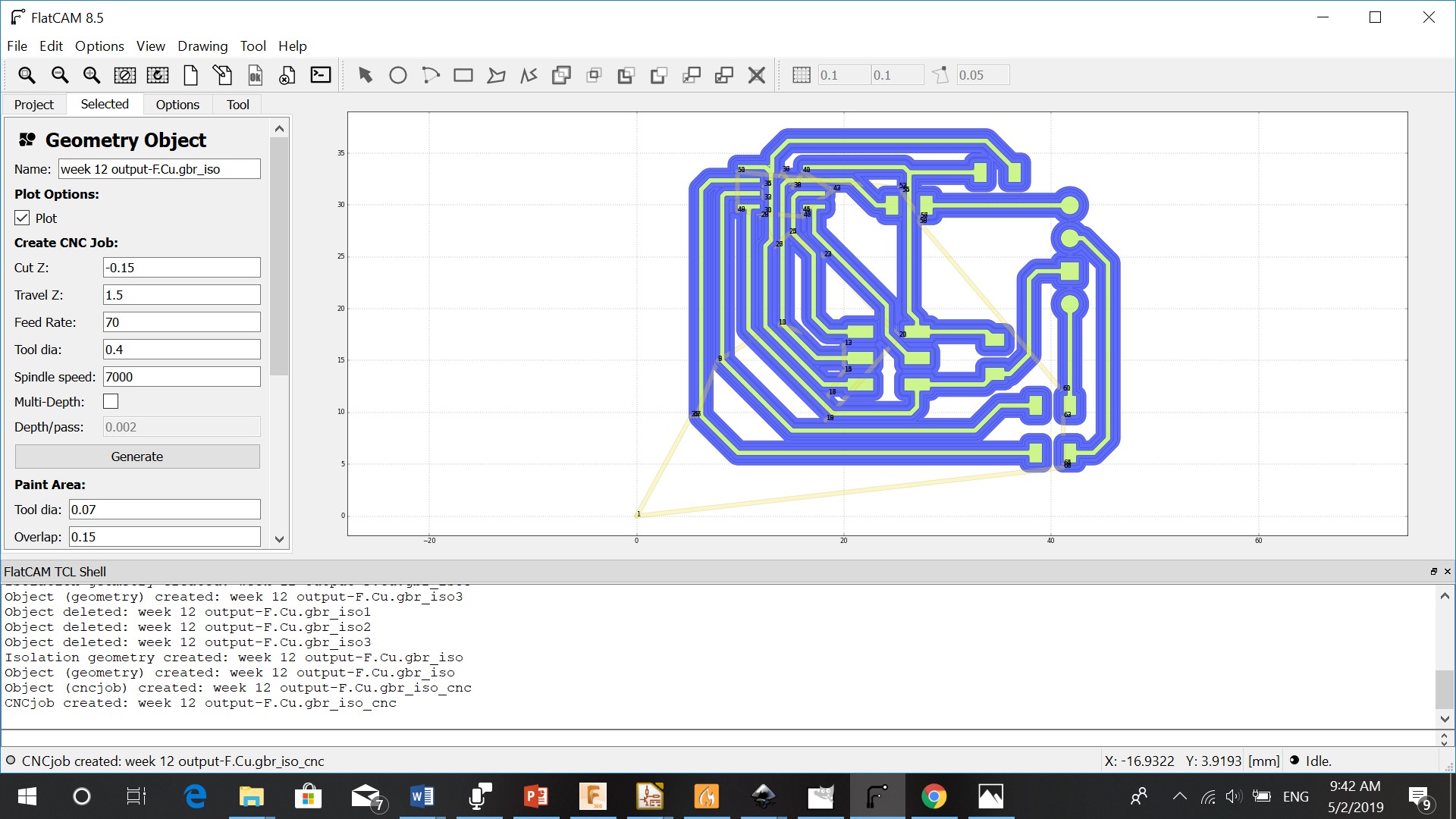
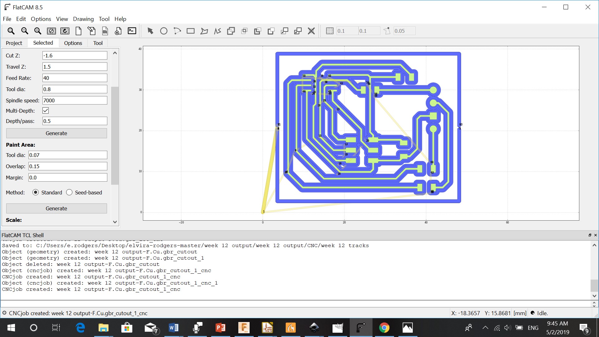
Cutout
For the cutout I clicked on the Gerber file in Project. I changed the tooldiameter to 0.8mm and generated the file.
I went to project and clicked on the file ending with _cutout
I changed the parameters to:
Cut Z: - 1.6
Travel Z: 1.5
Feedrate: 30
Tooldiameter: 0.8
Spindle: 7000
Check multidepht and set it at 0.5
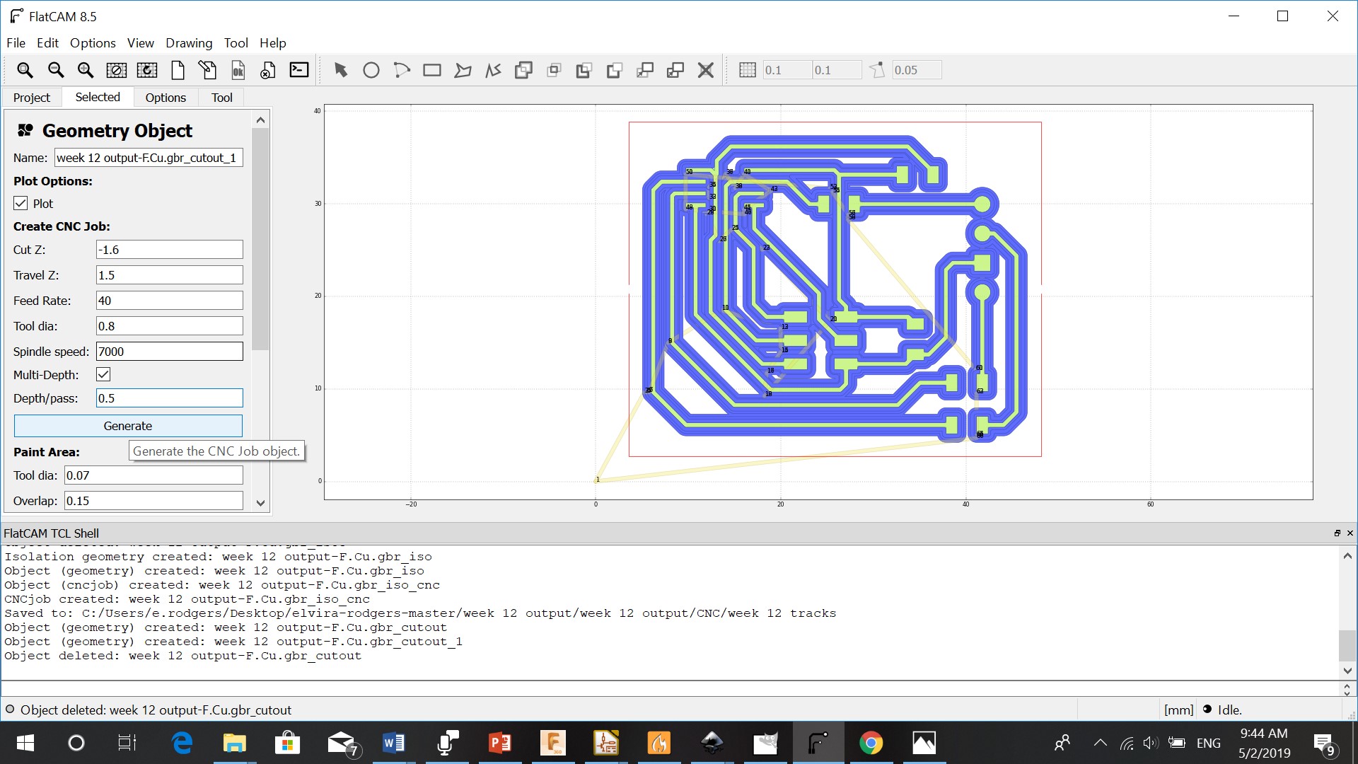
Generate
Milling
Just like in week 11 I set I set the X,Y and Z
Because the board can be oneven I had to set a heightmap. I used 4 for the X probe grid and 4 for the Y probe grid. This calculates the height of the board in 4 point to left (X), and 4 points to the back (Y)the heightmap
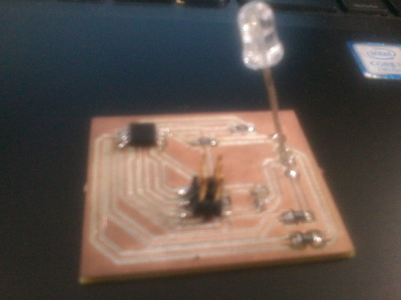
Soldering
After milling the board, I soldered the components on the board
Programming
After soldering the components on my board, I used the multimeter to see if all connections were right. I opened a new file and checked the pinout of the Atttiny 45. I had to choose pin 2,3 & 4.
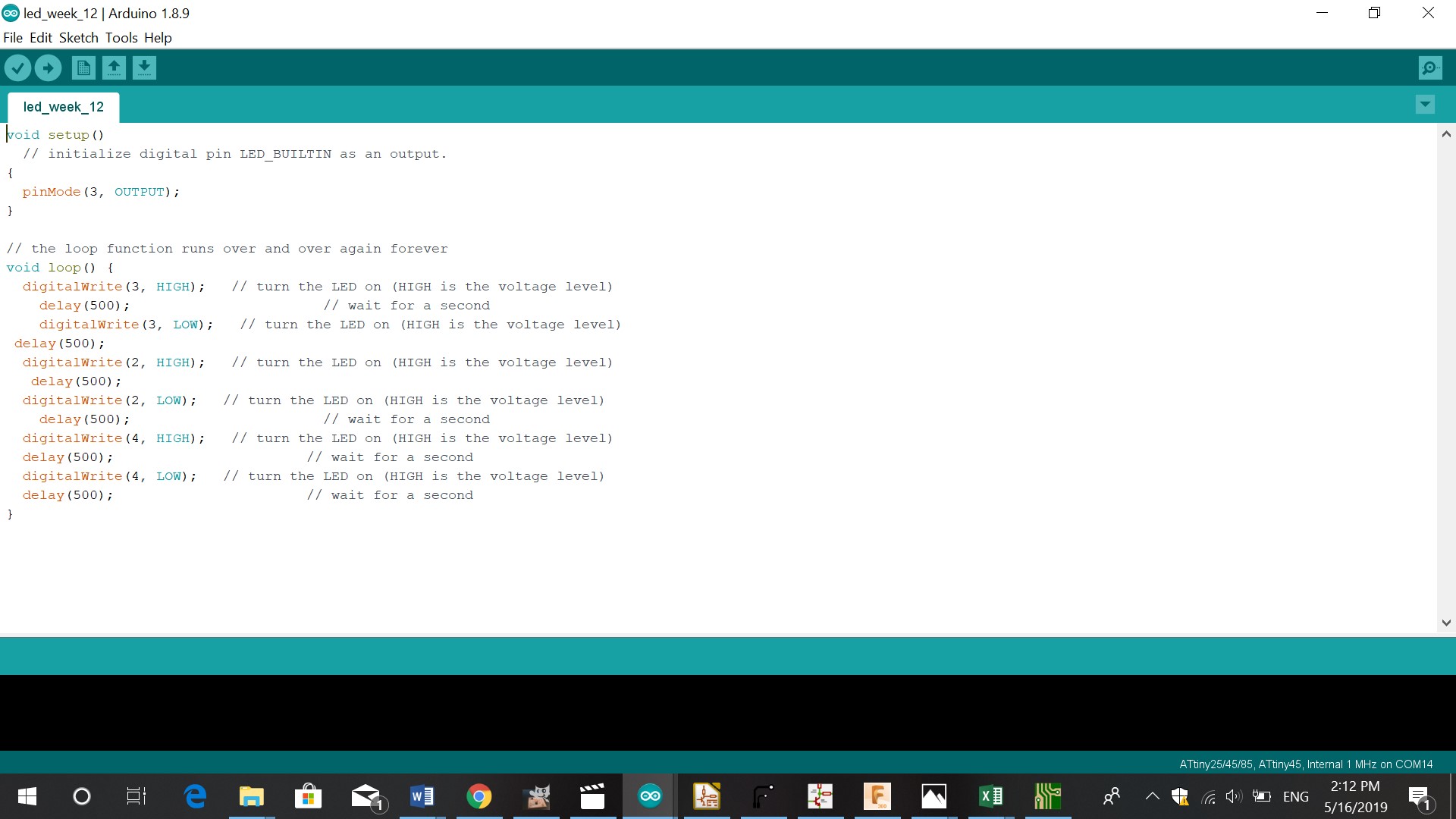
{
  pinMode(3, OUTPUT);
}

// the loop function runs over and over again forever
void loop() {
  digitalWrite(3, HIGH);   // turn the LED on (HIGH is the voltage level)
    delay(500);                       // wait for a second
    digitalWrite(3, LOW);   // turn the LED on (HIGH is the voltage level)
 delay(500);
  digitalWrite(2, HIGH);   // turn the LED on (HIGH is the voltage level)
   delay(500);
  digitalWrite(2, LOW);   // turn the LED on (HIGH is the voltage level)
    delay(500);                       // wait for a second
  digitalWrite(4, HIGH);   // turn the LED on (HIGH is the voltage level)
  delay(500);                       // wait for a second
  digitalWrite(4, LOW);   // turn the LED on (HIGH is the voltage level)
  delay(500);                       // wait for a second
}
The code used this week is based on turning on a triple colored RGB LED. So above codes tell the LED to turn on and turn of after half a second (the delay), after that the same for the second and the third LED.
Problems
The LED didn’t get enough power, so only the green light lit. The blue and red light gave a tiny spec of light.