Week 7 Electronics design
This week we had a group assignment and an individual assingment
Group assignment
For the group assignment we had to use the test equipment in our lab to observe the operation of a microcontroller circuit board. For more info regarding this weeks group assignment click here.
Individual assignment
KiCad
For the individual assignment we had to redraw the echo hello-world board add (at least) a button and LED (with current-limiting resistor)check the design rules, make it, and test it extra credit: simulate its operation extra credit: render it.
The components needed for the assignment were: 1. ATTiny44-SSU, microcontroller 2. AVRISPSMD, 2x3 header 3. CAP UNPOLARIZEDFAB, 1uf capacitor 4. RESONATOR, 20MHz crystal 5. LEDFAB1206, one green for power 6. RES-US1206FAB, resistors: (2) 1K ohm, (2) 10k ohm 7. SWITCH-6MM, button
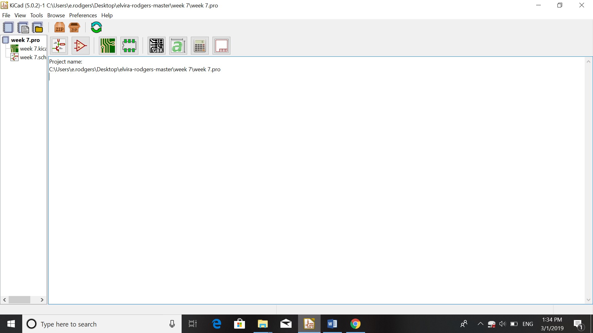
For this assignment I first downloaded KiCad on my computer. I then started a new project by opening KiCad and clicking on the first icon in the second row (looks like a book).
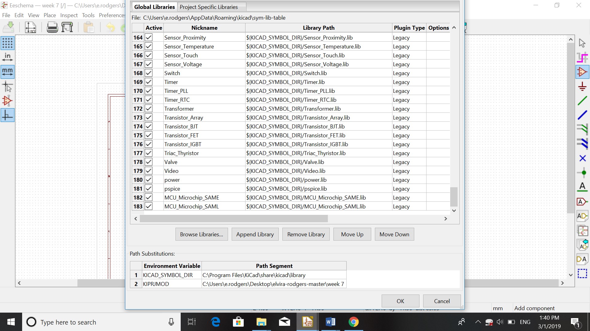
I then opened the schematic layout editor which gives a list of components. For the list that I needed I went to fabacademy.org and downloaded the KiCad files from the Git Libraries.
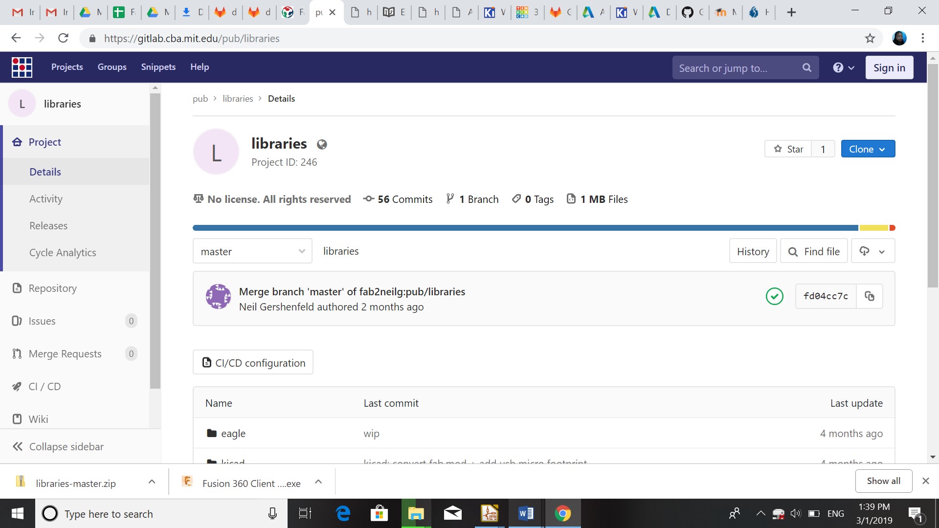
In KiCad I opened preferences and configure paths. I browsed through library, added Fablib and ok.
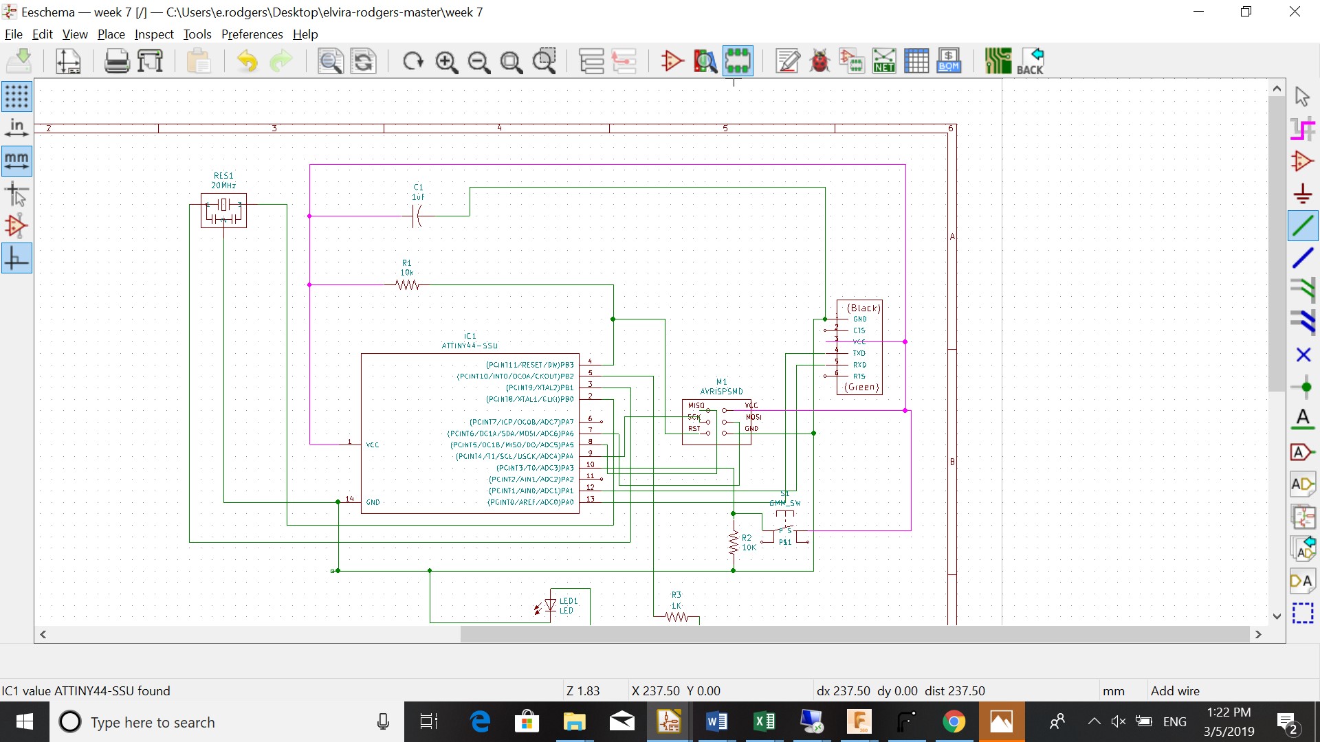
By placing symbol (3th symbol on the right)I could assign the components. After assigning the symbols I placed the wires to make the connection between the components.
I then followed these steps:
-
Click on annotate twice
-
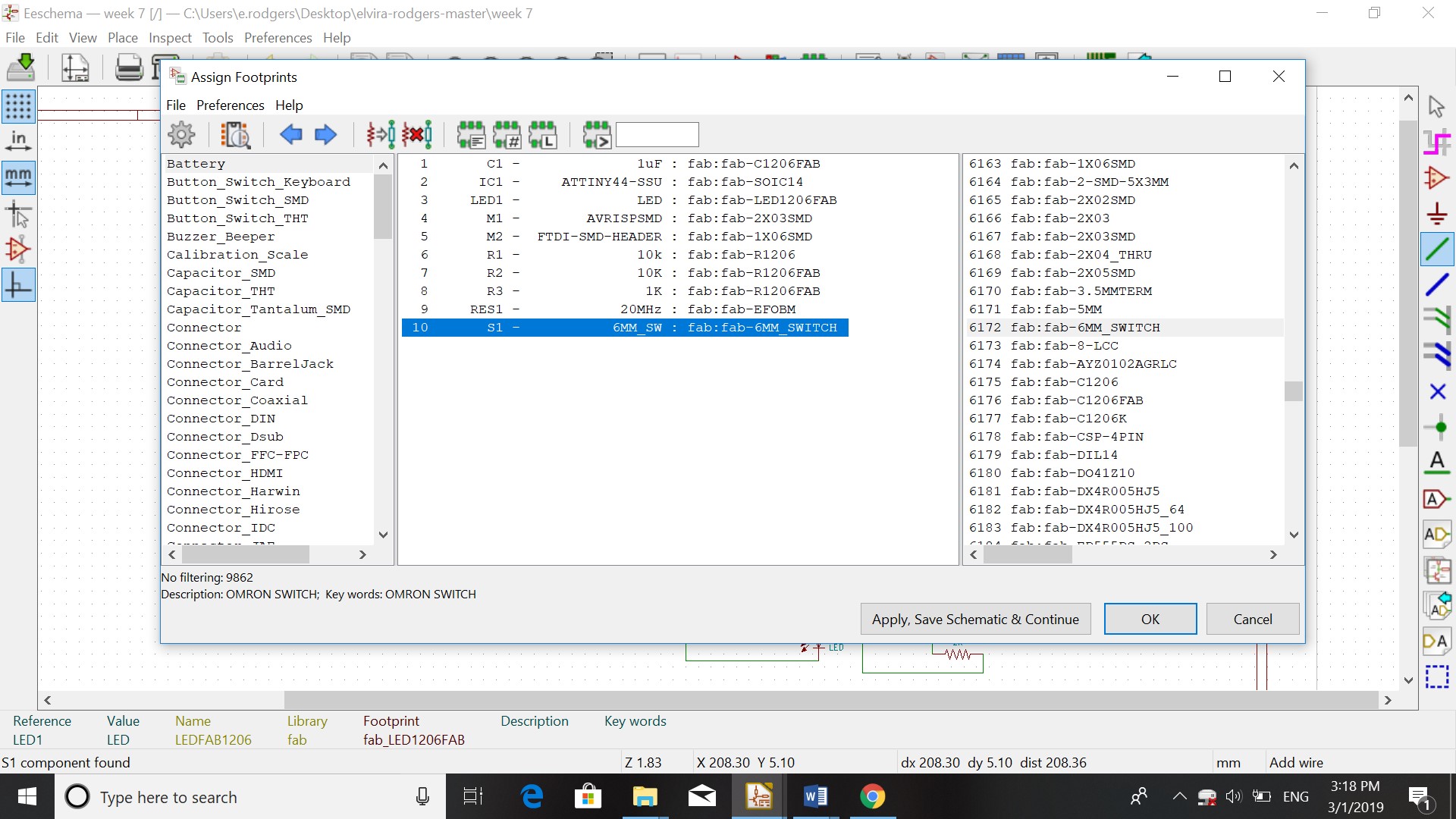
Assign footprints
-
You get a list with your components. You search for the components in the list left and click on the name of the component twice (right). you repeat this till the last component.
-
Apply schematic
-
Ok
-
Generate Netlist
-
Save in folder
-
Tools
-
Update PCB from schematic (make sure there are no errors)
-
Using route tracks the lines can be redrawn
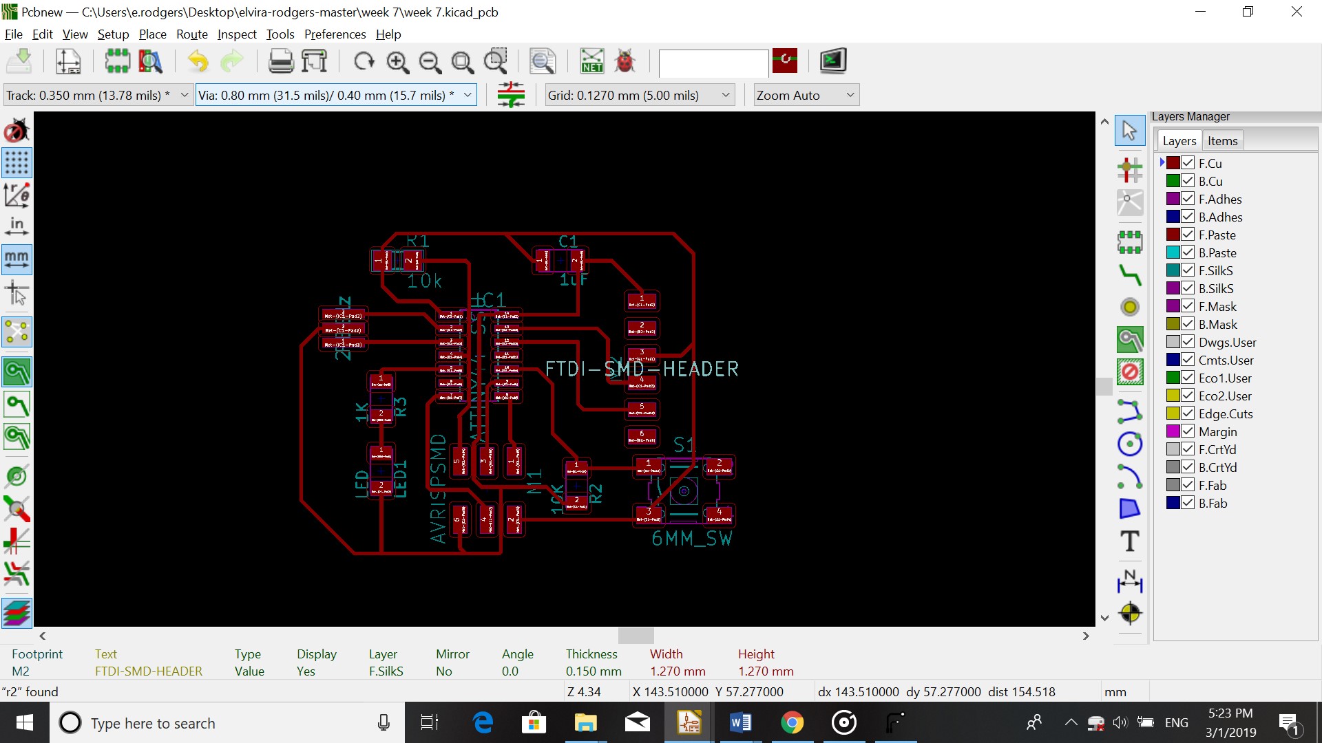
With Place/Drill and place offset I set the startingpoint for the drill. Make sure that “Use auxiliary axis as origin” is checked (File/Plot) and the close plot.
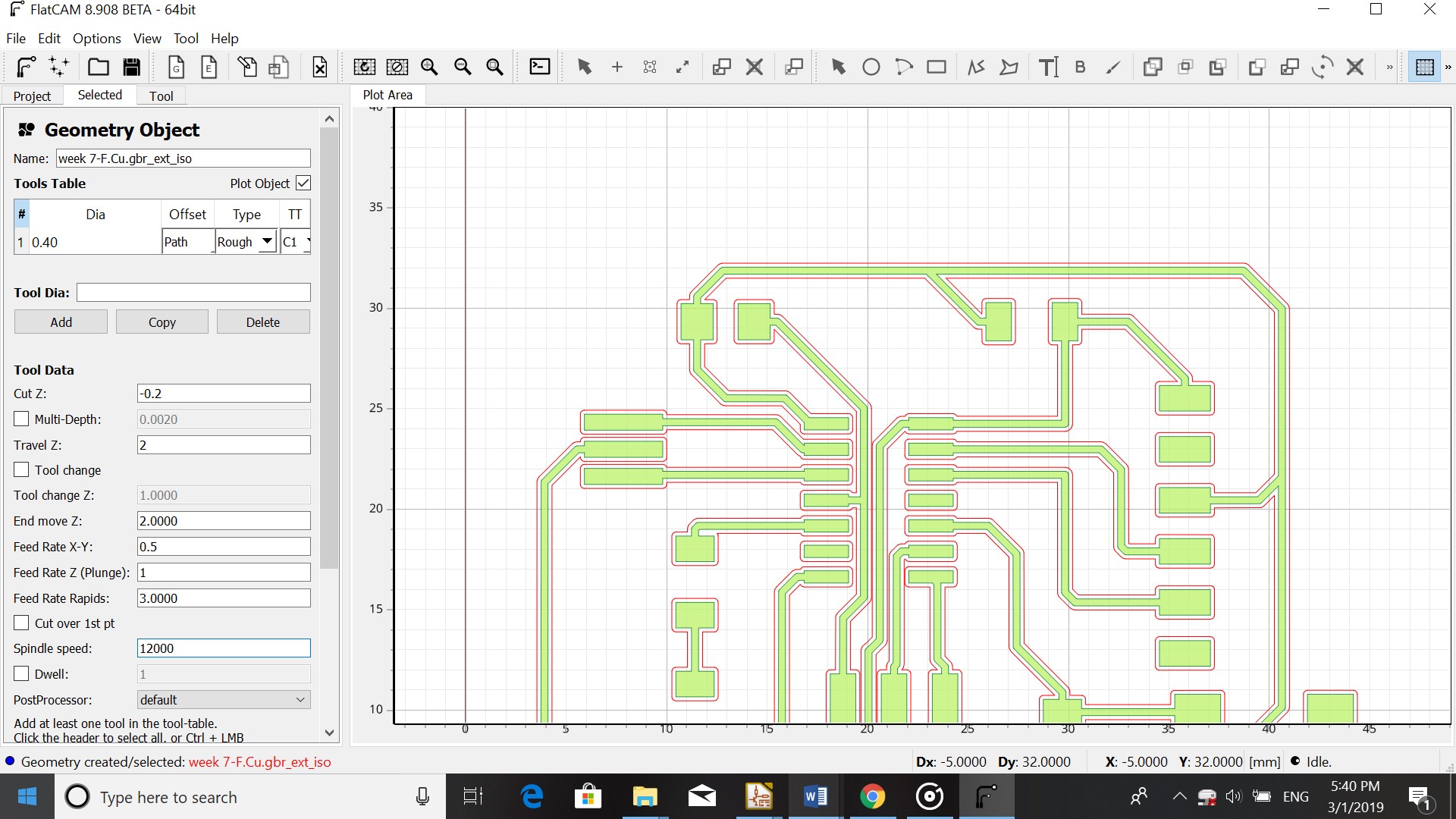
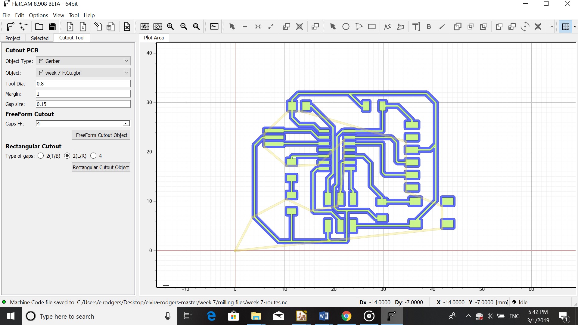
FlatCAM
In FlatCAM I opened the file using File-open Gerber and generated it. I then went to Tool-Cutout PCB (to see if cutout is right) and double clicked on the name of the design. I changed the parameters in
-
Cut Z: - 0.2
-
Tool diameter: 0.4
-
Travel Z: 2
-
Feedrate x,y: 0.5
-
Feedrate z: 1
-
Spindle: 12000
-
Generate
For the outside of the board I used these parameters:
-
Cut Z: -1.5
-
Multi depth: 0.5
-
Spindle speed: 12000
-
Passes: 3
After I saved the file in FlatCam, I opened my route in WinPC-NC USB. I checked the parameters and checked the coordinates on Zero point in file as origin of coordinates. I checked the spindle, set a zero point and did a test. For printing I set the speed to 120%.

.jpg)
I had to mill my board 3 times because I kept getting an error in the middle of milling which caused the machine to stop. I Changed the laptop which I was using and I could mill my board.
Programming
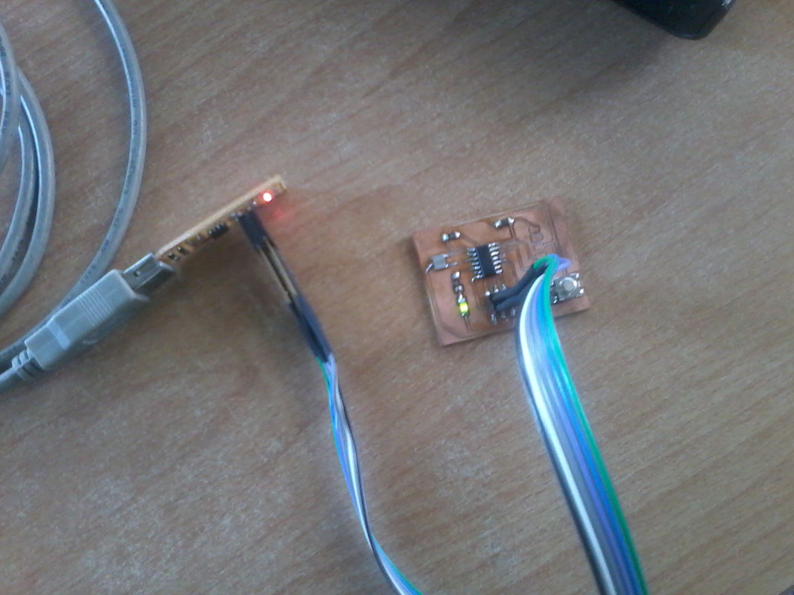
After milling the PCB I soldered the components mentioned above on the board.
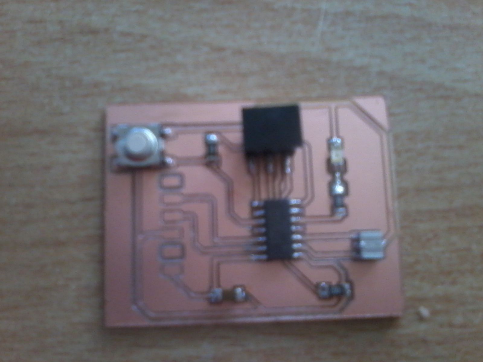
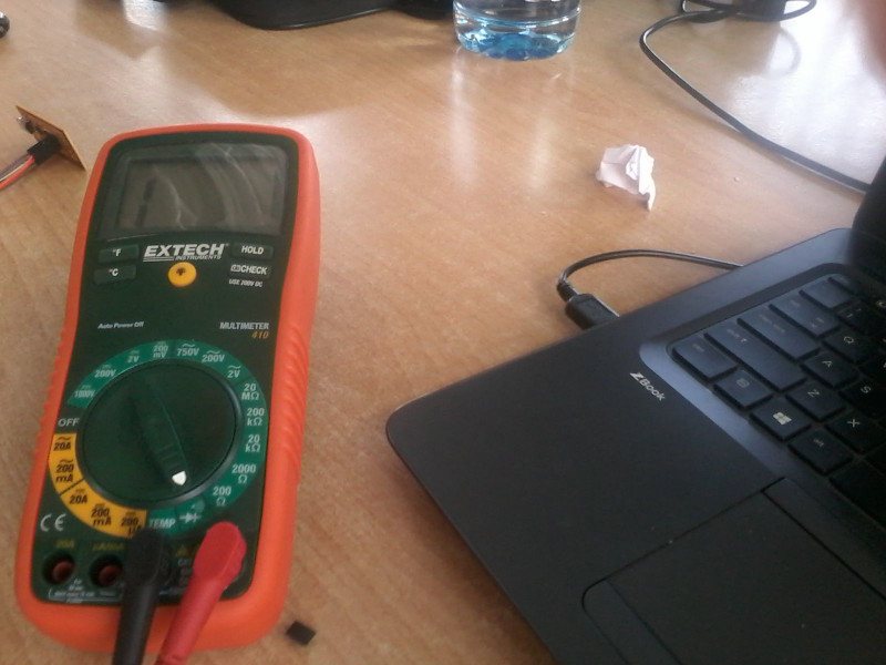
I checked if all the components were soldered right with the multimeter.
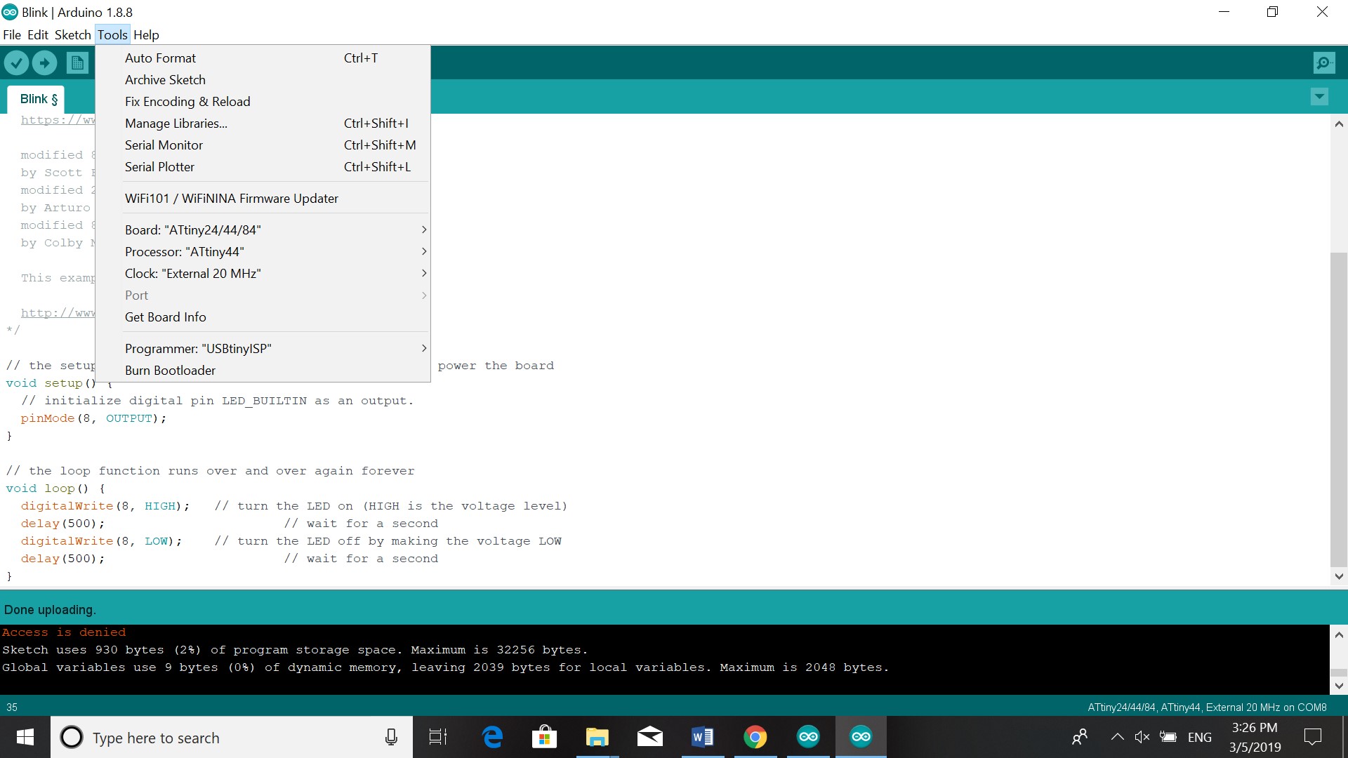
Before programming the board I downloaded and installed Adafruit (software to recognise programmer). Via device manager I checked to see if I could see USB Tiny. I downloaded arduino 1.8.8. In tools I changed the board to Attiny 24/44/84, processor to Attiny 44, clock to External 20 MHZ. I googled Attiny pinout to see to which number I should change the pinmode and the digital write. tried burn bootloader but this gave an error. The board was resoldered about three times and after that burn bootloader worked (but with Arduino 1.8.7 on another laptop). The LED lit.