Week 4 Computer controlled cutting
This week we had to do a group assignment and a individual assignment.
Group assignment
For the group assignment we had to characterize our lasercutter’s focus, power, speed, rate, kerf, and joint clearance. For more info about this week click here
Lasercutter
The lasercutter we used is a RS-1060L with a 90W CO2 tube. It has a work area of 1000 by 600 mm. Before we started testing we had an introduction about using the machine and how to safely work it. What you must do when starting with you lasercutter is switch on the air extractor, turn on the power of the lasercutter and check if the CW-3000 Industrial Chiller is also on. When you hear 2 beeps, it is on.
Test 1
The first test was to cut circles, squares and triangles at different powers and focus using a mdf-like material with a thickness around 2.3mm. We used
Power: 30% 60% 90%
Speed: 20% 20% 20%
Focus: 8mm -1mm -2mm
We measured the outside square width and forgot to measure the inside square width. So we had to perform another test. The conclusion was that the best cut and the best square precision (outside square width=5.0mm) was 90% at a focus of 6mm.
Test 2
The second test was to cut squares at different powers and focus. The squares were cut at these powers and focusses:
Power: 60% 80% 95%
Focus: -1mm -2mm -3mm
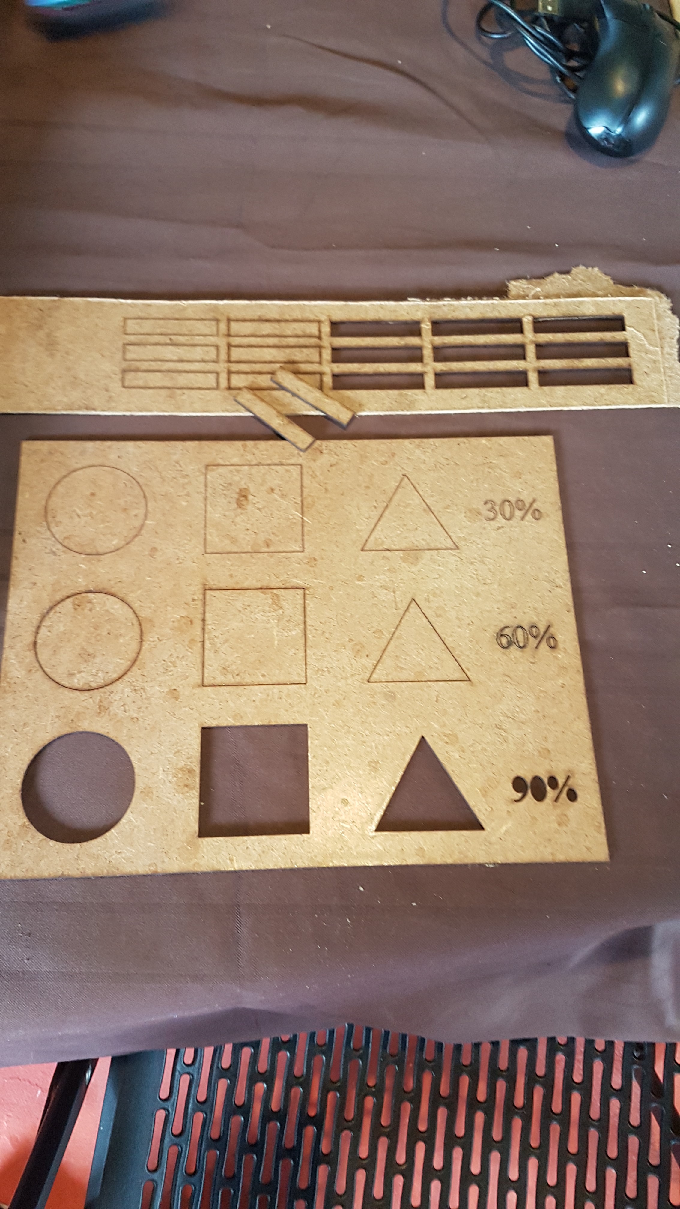 Image test 1 & 2
Test 3
Third test our instructer performed the regular maintenance and he realized that the curved size of the lens was turned down. By checking the documentation, we realized that it was upside down as we can see on the picture below. Therefore we relaunched our tests and get to the conclusion that the best focus is, as adviced by the manufacturer, at 8mm. Our results about the laserkerf stayed at 0.05mm at 60% power.
Individual assignment
Press Fit Kit
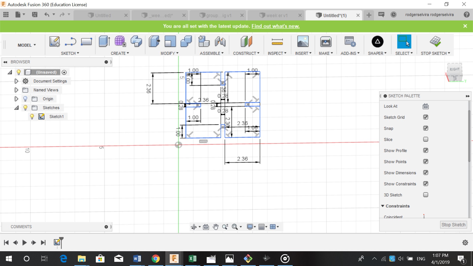
For the individual assignment we had to create a press fit construction kit. For this assignment we used cardboard with a thickness of 2.3 mm. I designed the pieces in Fusion 360. I started out making a sketch, I used 5 cm by 5 cm for the pieces. For the pieces to fit into each other I made a kerf in the middle of 1 cm by 0.23 cm. The width of the kerf is the same as the thickness of the material because t has to fit.
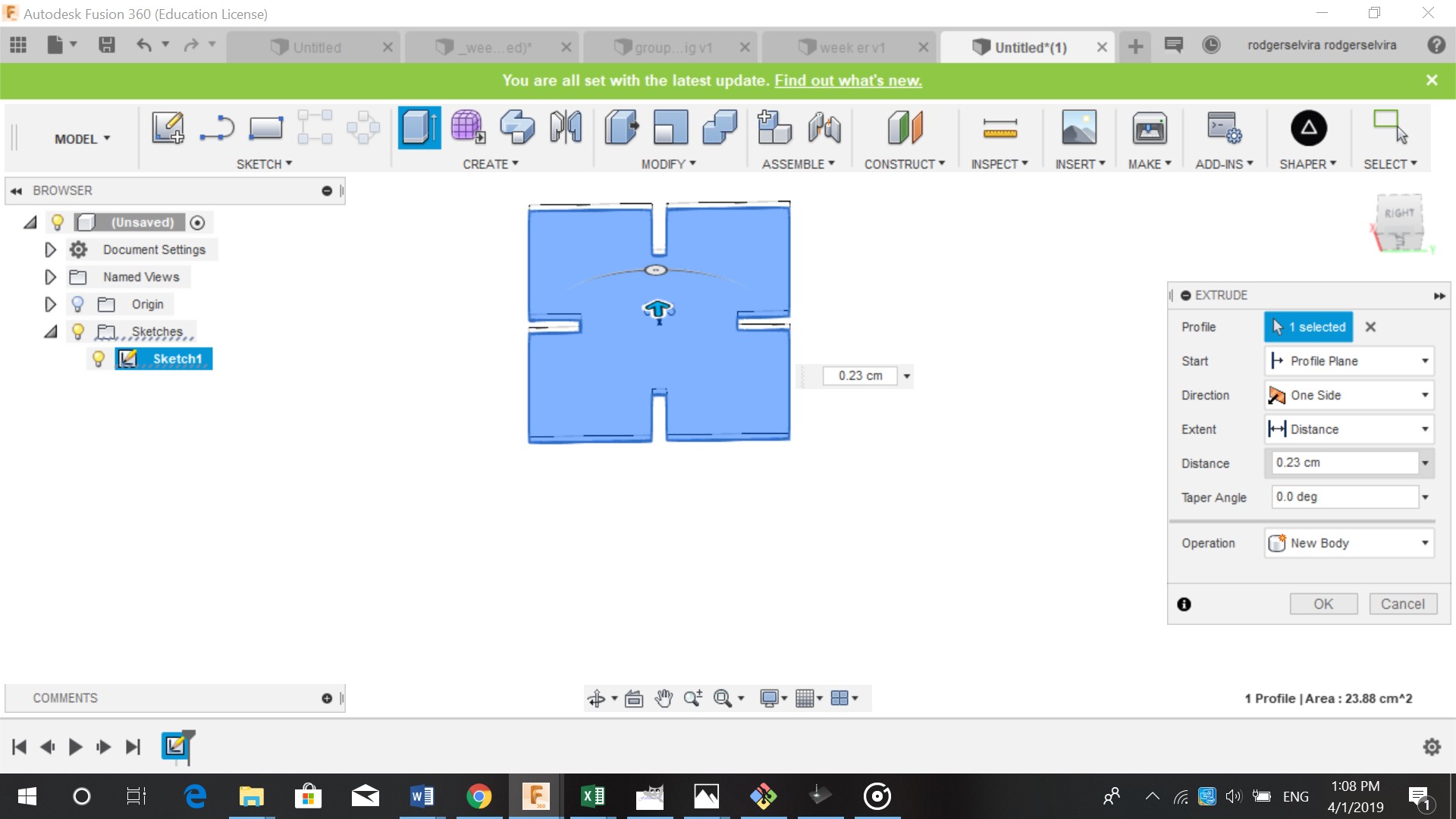
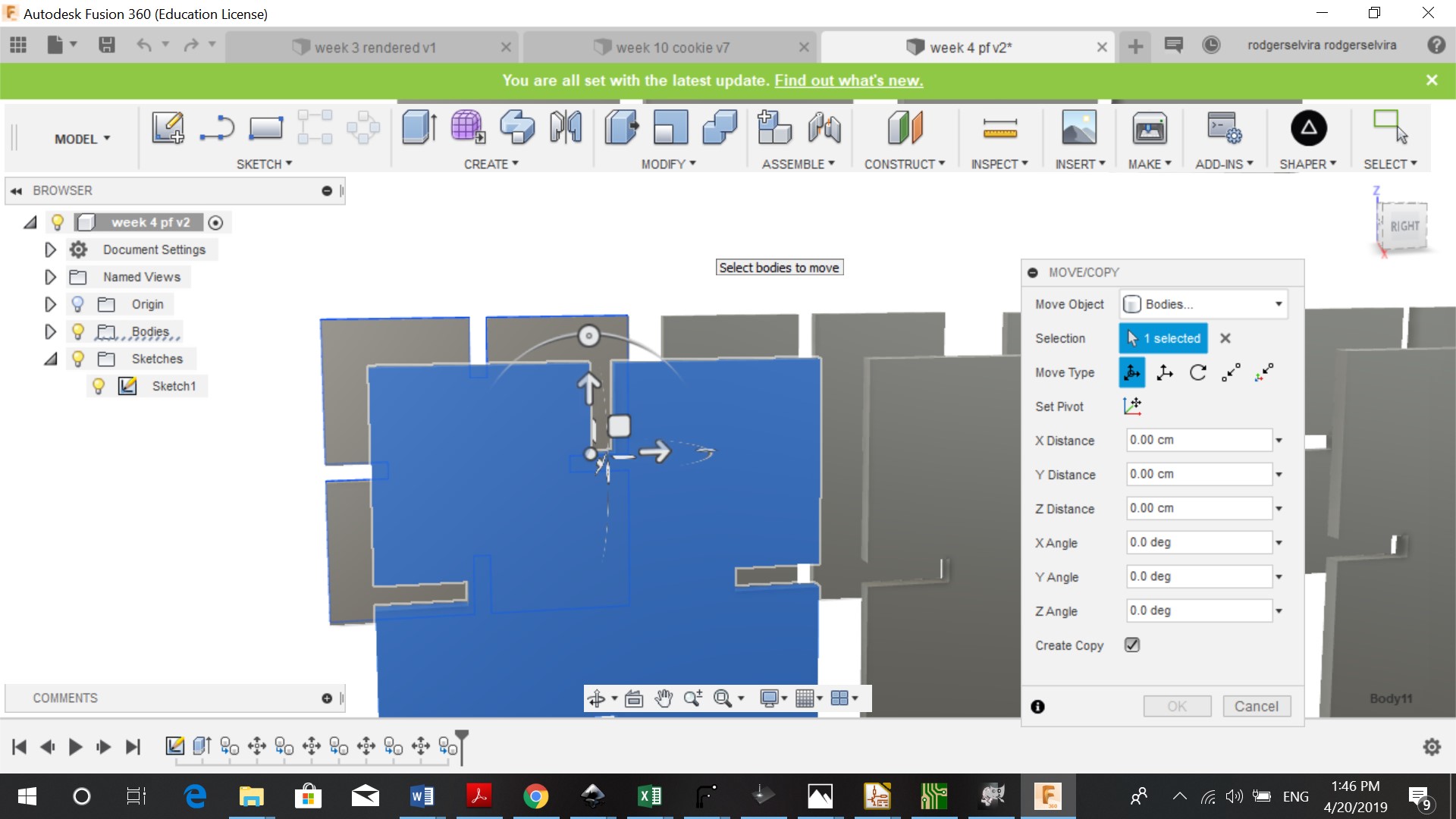
After sketching the design I extruded it by 0.23 cm. And made multiple copies of the design by clicking on move/copy. You can select the body and click on make copy. You can move the copy of the body using the square inf front of it.
We also had to download Shaper (one of Fusion 360 add ins).After downloading Shaper, Fusion 360 needs to be restarted and the file reopenend. I then followed these steps:
-
Shaper
-
Export origin
-
Select the face
-
Name your SVG
-
Ok
Visicut
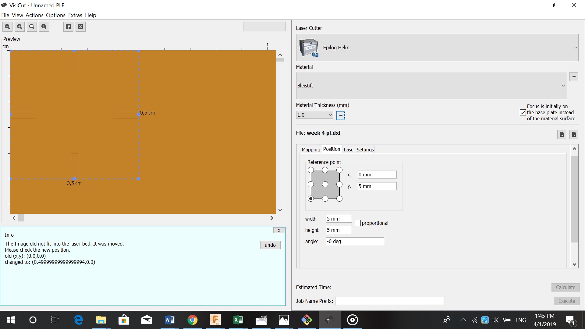
In visicut we had to follow a few steps before starting to cut
-
Open file in visicut
-
Import file
-
Position (always from bottom left (x,y), (0,0))
-
Change width/length 180/180
-
Export G.Code
-
Enter g.code after file name
-
Enter IP adress (on the machine)so you can control machine from tablet
-
Place board
-
Close door
-
Select file map
-
Wear glasses (safety)
-
Print
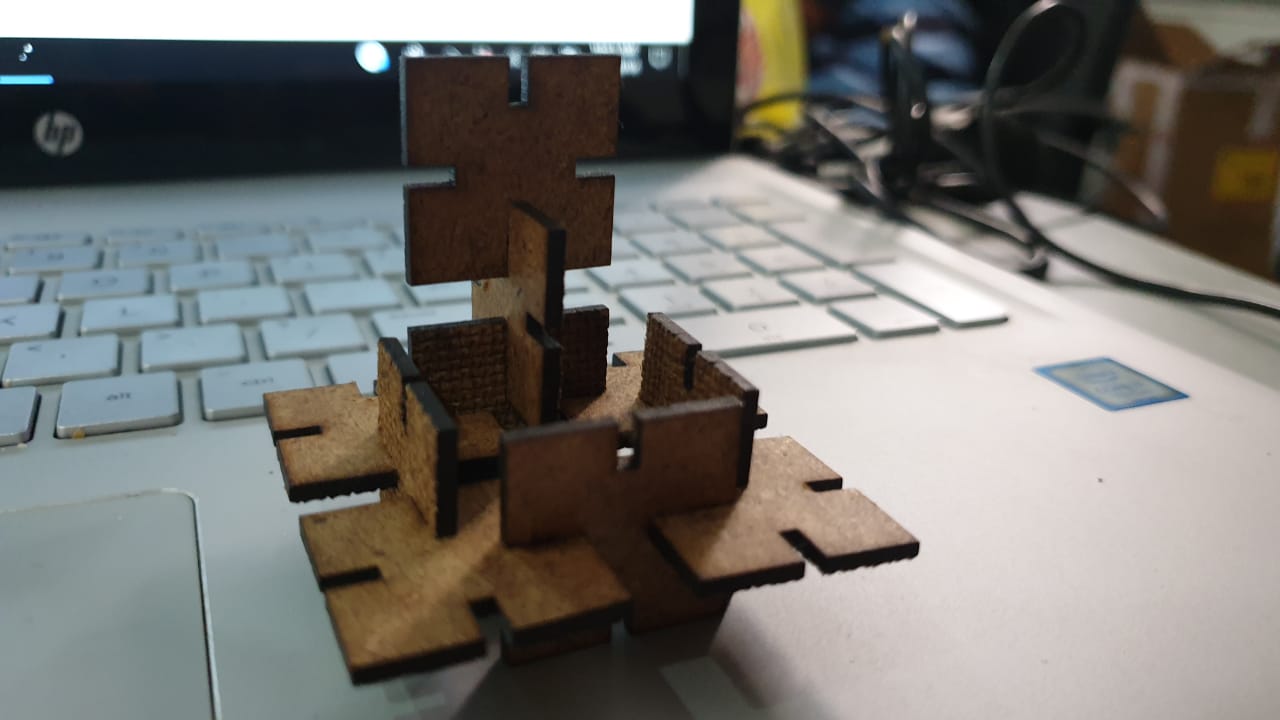
I liked my pressfit kit. The only thing I would do to change it is making the pieces bigger. Because the pieces were 5cm and came out small.
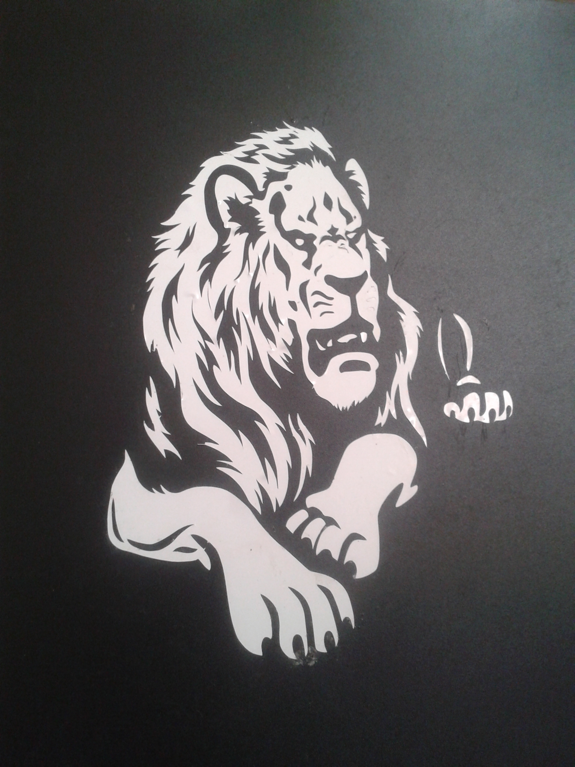
Vinyl cutter
Before using the vinyl cutter we had to:
-
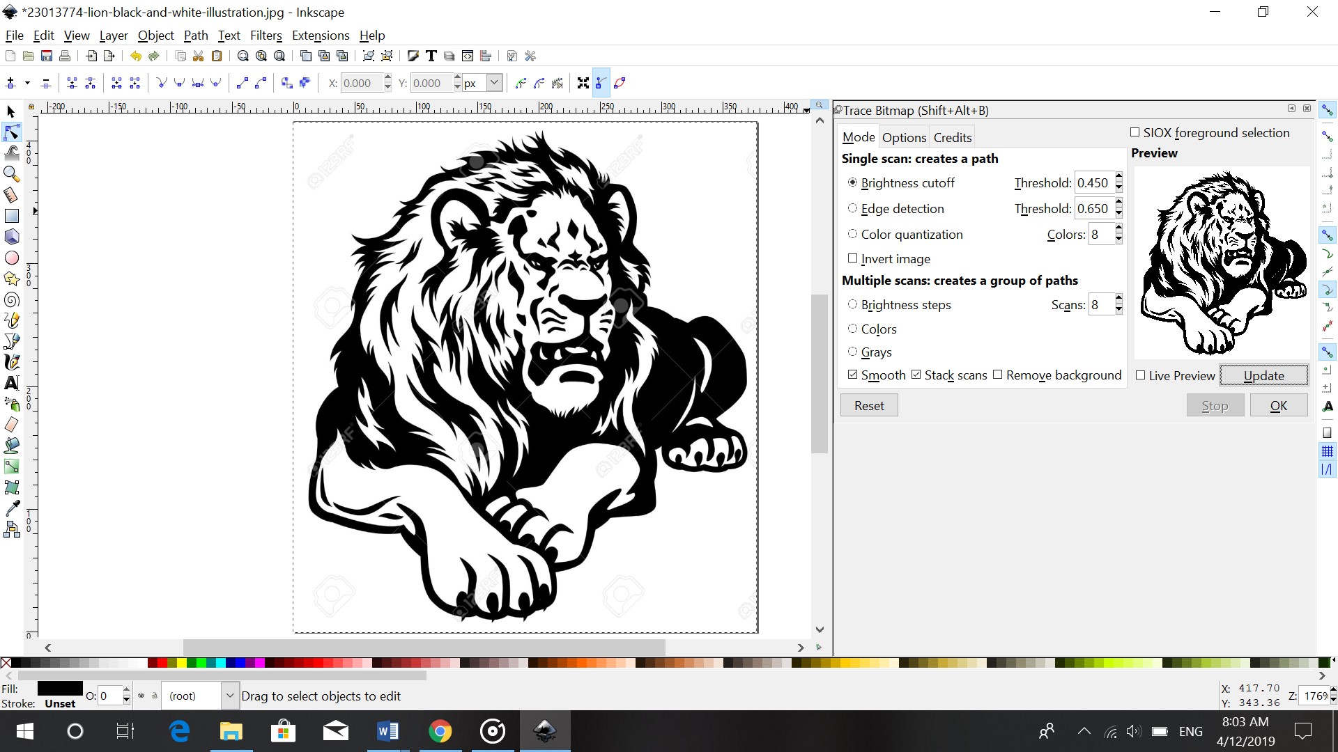
Choose an image. I chose this image
-
Open the image file in Inkscape

-
Path
-
Trace Bitmap
-
Remove original
- Edit paths by nodes to remove unwanted lines

- save as svg
After saving the SVG file I opened it in Canvas workspace (This converts file to a readible file for the vinyl cutter). There I resized it and saved the file on my USB stick.
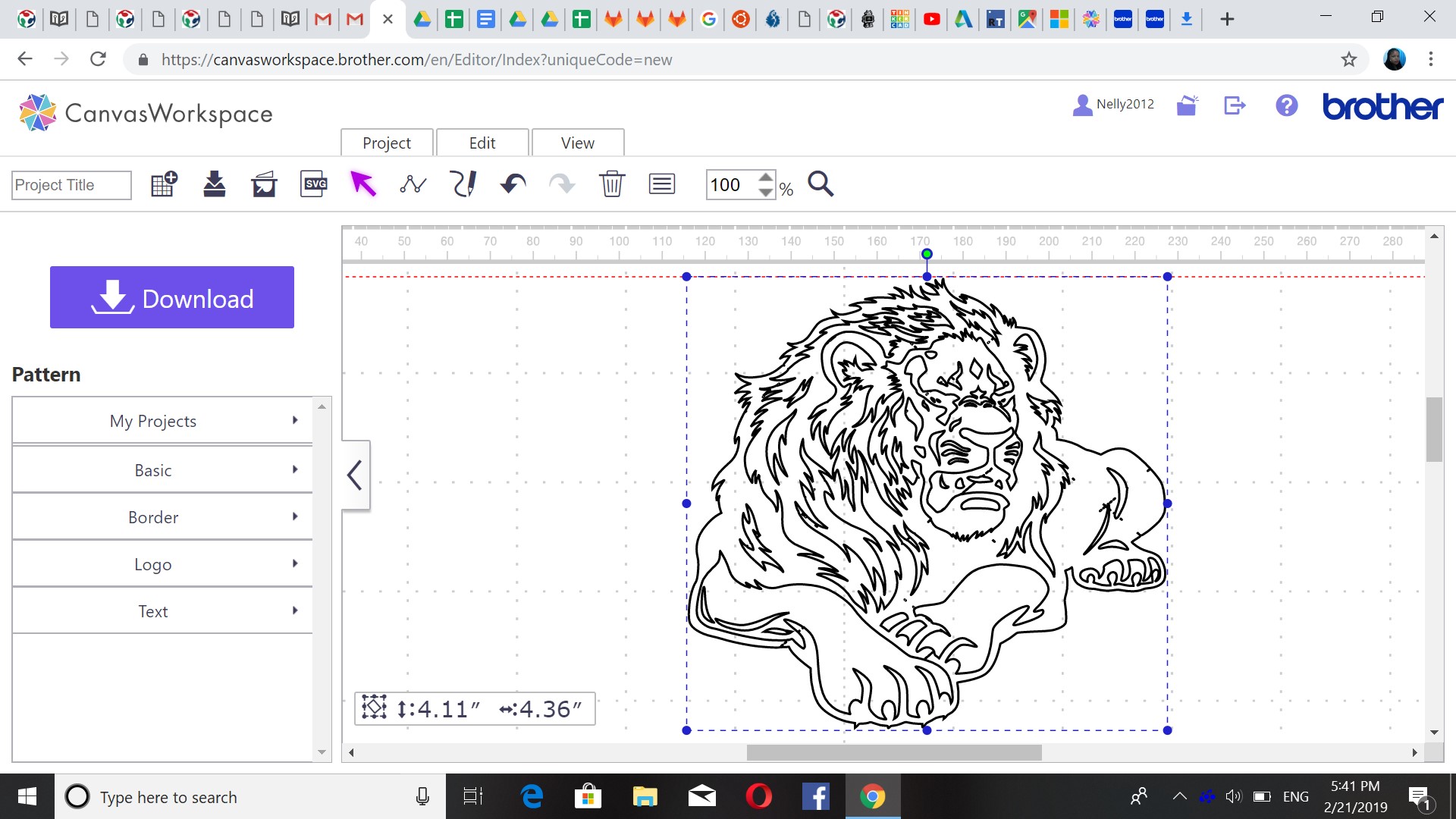
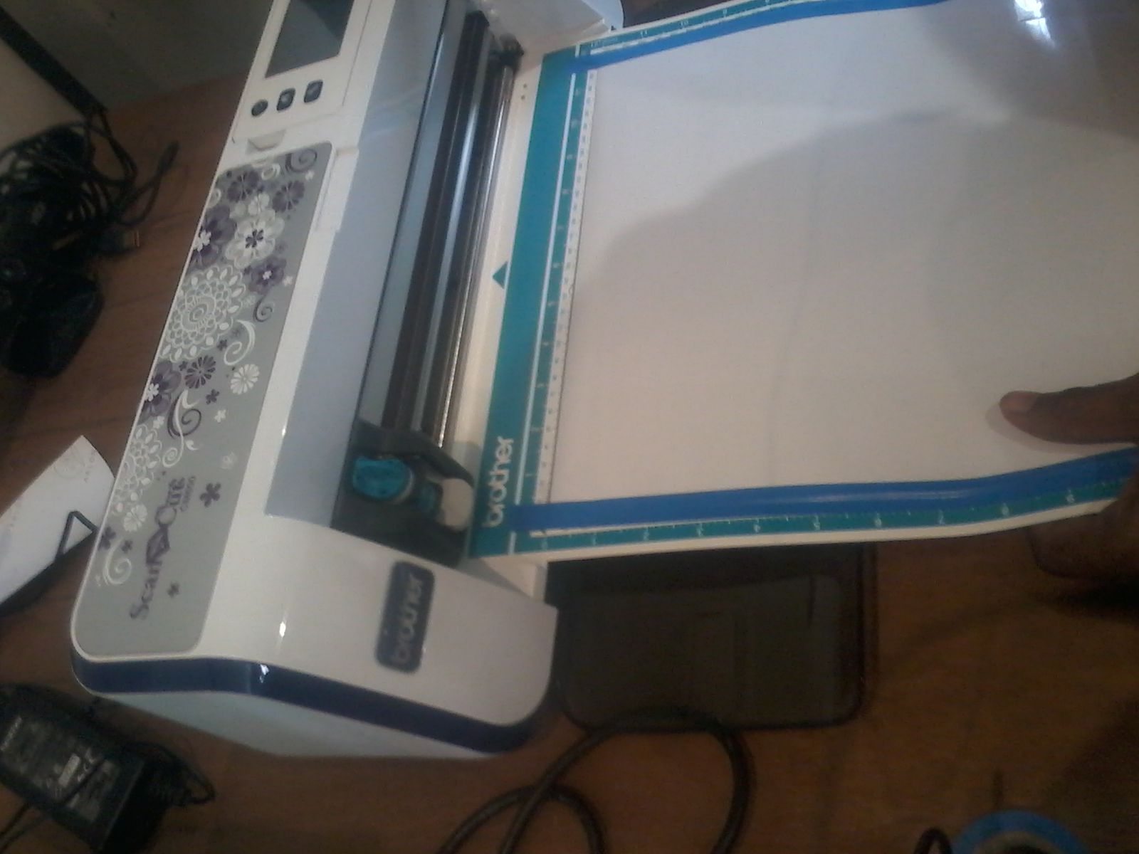
I inserted my USB stick in the machine (Brother Scan N Cut CM600), I taped the outsides of the sheet so it move smoothly into the machine. I then went to the menu button and selected the file that had to be cut.
The result of my vinyl cut. It came out nicely but took a lot of work to remove unwanted pieces.