Week 8 Computer controlled machining
Group assignment
This week our group assignment was to work on testing the runout, alignment, speeds, feeds, and toolpaths for your machine. Further info can be found by clicking here
Individual assignment
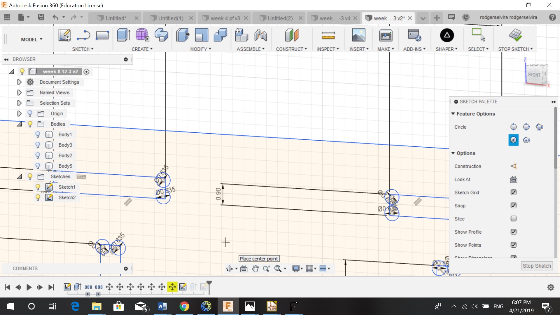
For the individual assignment we had to make something big. I designed a shelf in Fusion 360. My shelf was innitially design to put toys on it, but it is multifunctional and can also be used for example as a book shelf. The size of the shelf is 70 by 30 cm. I first made a sketch of the back, the sides and the shelves. I then made rectangles were the conncetions should be. Because of the fitting we had to turn the rectangle into a dogbone. I took 1 mm from the rectangle and made that as my middle point for the circle. Because of the bit we used to cut our wood, we worked with a diameter of 6.35 mm for the dogbone. The width of the rectangle is 9 mm.

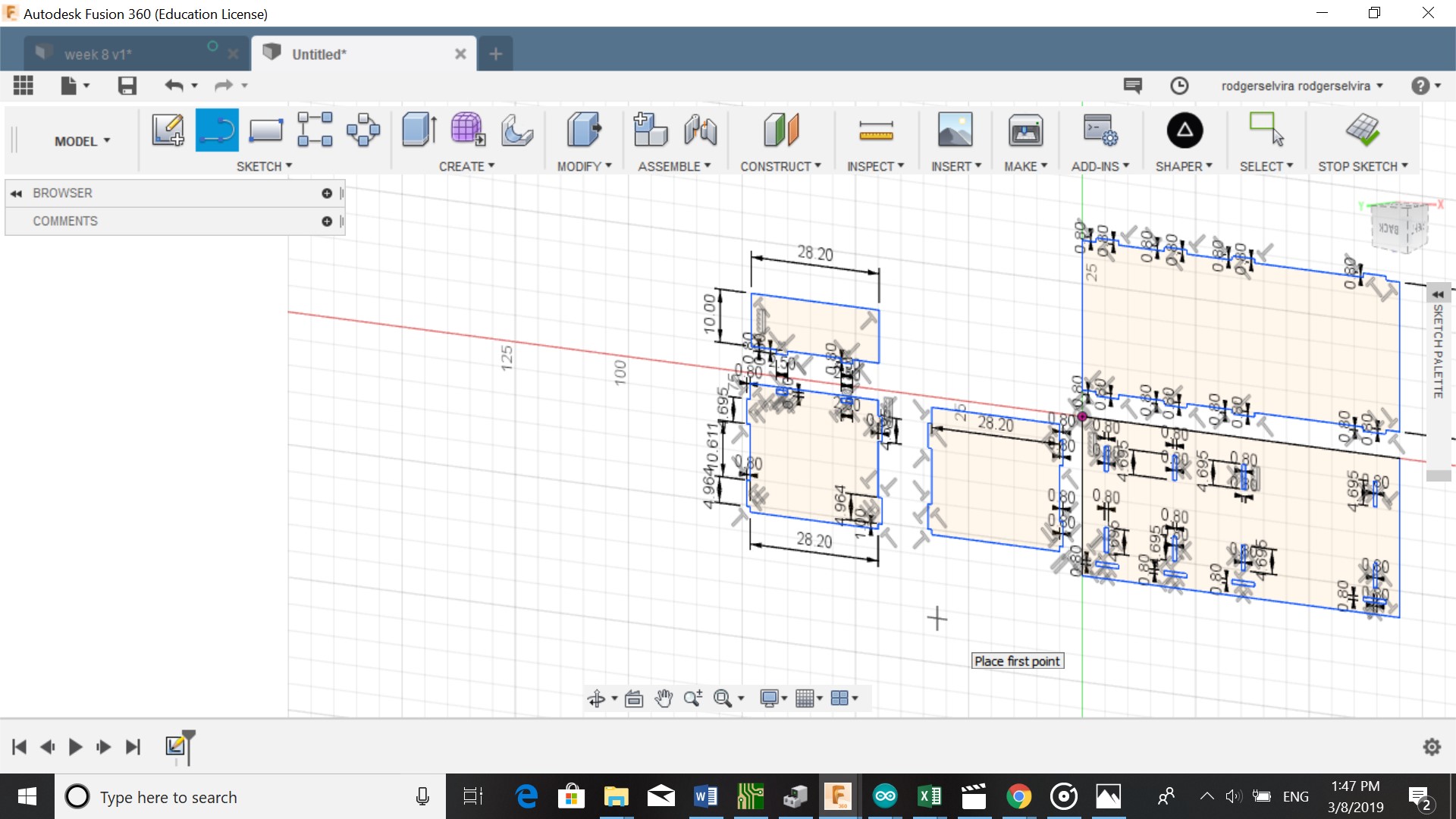
After skectching I extruded the sketch by 9 mm because of the thickness of my material.
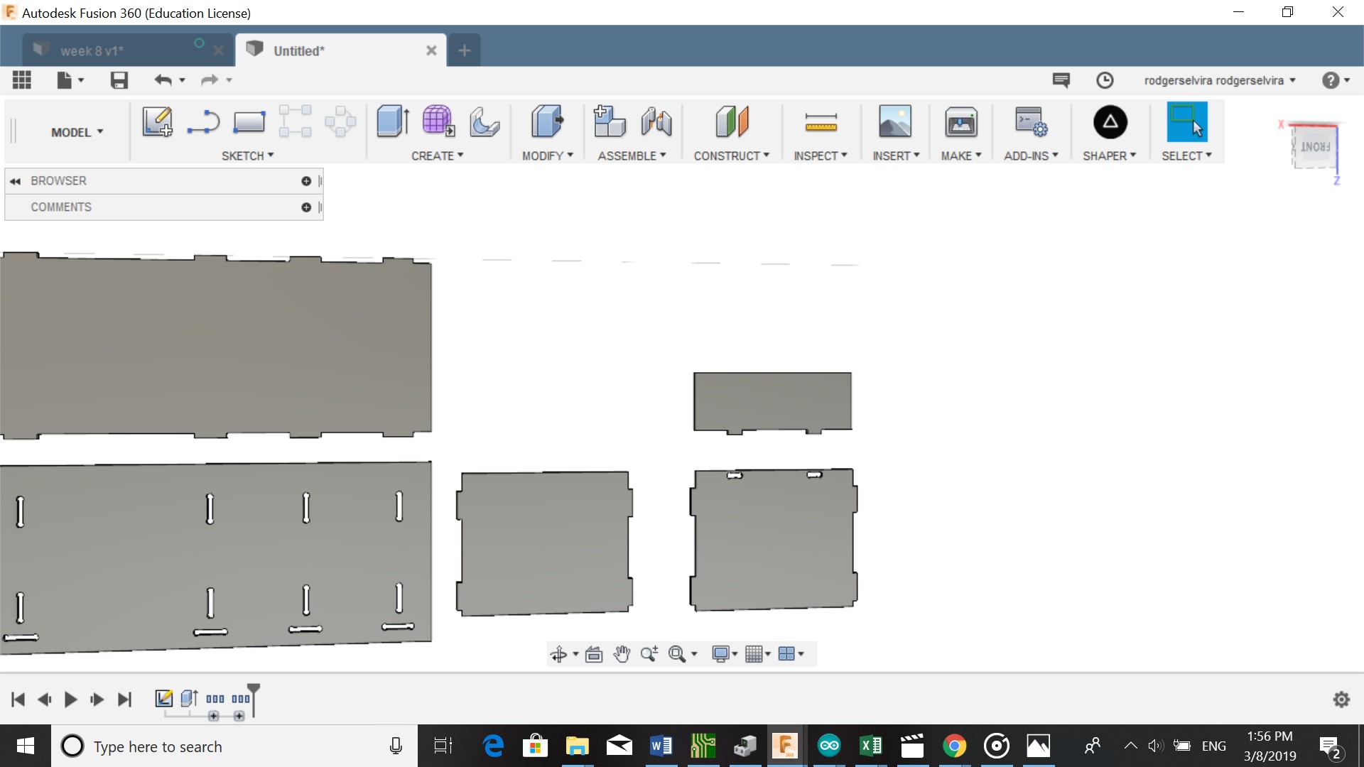
And saved the file as a DXF file.
Cutting the board
Aspire
Before cutting the board we had to install Aspire 9.0 on our laptop because of the Shopbot that we used. The material used to cut was MDF 9 mm. It has a width of 2,44 m and a height ot 1,22 m. I saved my design as a DXF file. And opened it in Aspire.
In Aspire I followed these steps:
-
Change Jobsize in jobsetup (unit= mm, width= 2440mm, height= 1220mm,thickness= 9mm)
-
Ok
-
After you click ok another window opens. You can check the connection of the bodies by selecting them, the body
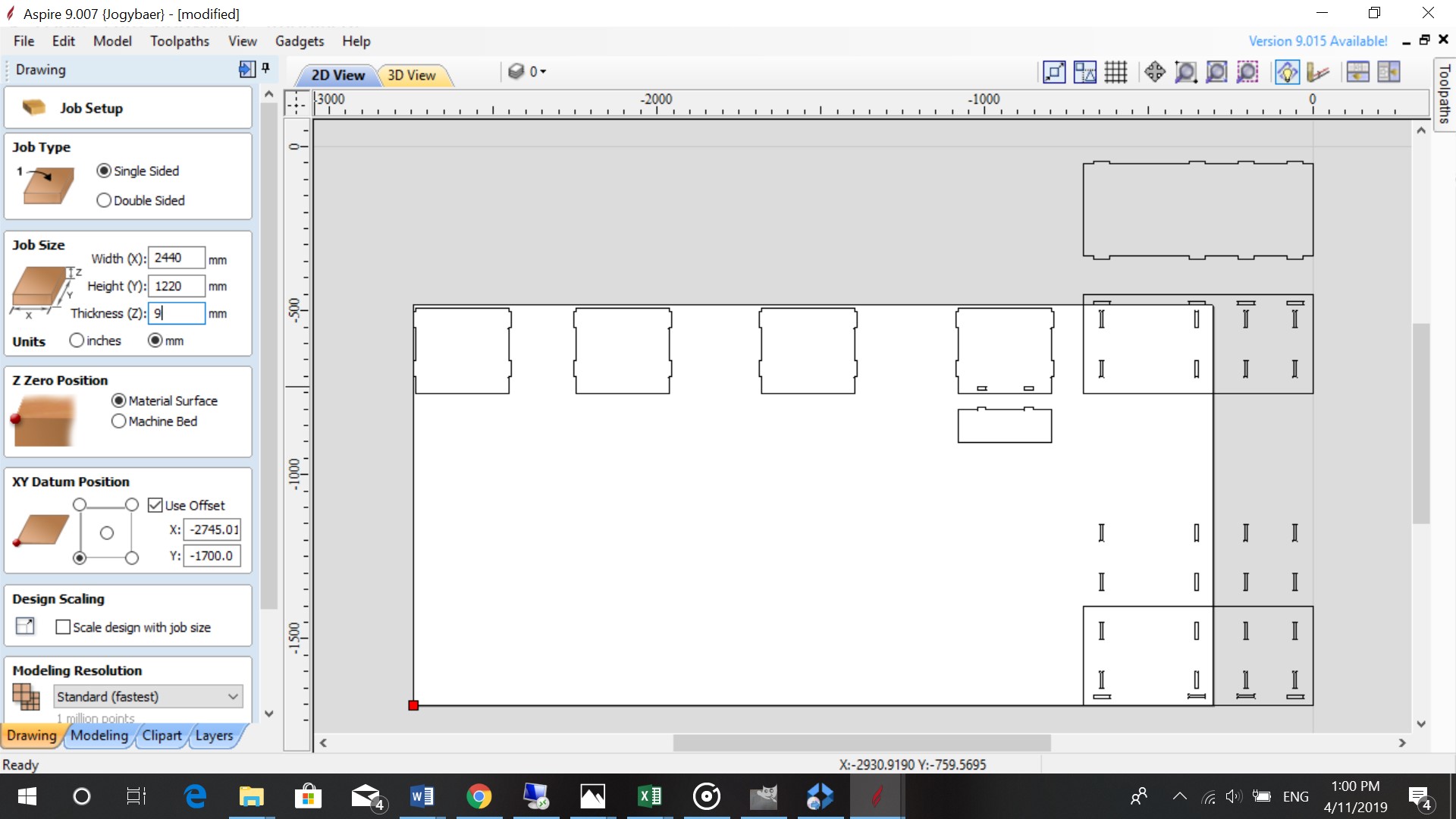
Setting up Jobsize
My design did not fit within parameters of the jobsize. After being resized in LibreCad, it didn’t give any problems. I reopened it in Aspire
Go to toolpath (right corner)and follow these steps:
The first part was to make a toolpath for the inside vectors
-
I selected the bones in my design
-
Profile path (start depht= 0, cut depht= 9.3 mm)
-
Tool (endmill=5/32”, diameter= 0.15, speedrate= 30 inch/min)
-
Machine vectors(inside)
-
Give toolpath a name
-
Calculate
-
After the toolpath is calculated, you click on the name of the toolpath, search for shopbot inch and add toolpath
The second part was to make a toolpath for the outside vectors
-
I selected all of the sketches
-
Held shift in and deselected the bones
-
Profile path same as the bones
-
I added tabs (length= 0.4 mm, thickness= 0.4 mm)The tabs are where the machine leaves a small piece so the object is still connected to the board.
-
Tool same as the bones
-
Machine vectors (outside)
-
Give toolpath a name
-
Calculate
-
Search for shopbot inch and add
-
Save file
Making the toolpath
Shopbot
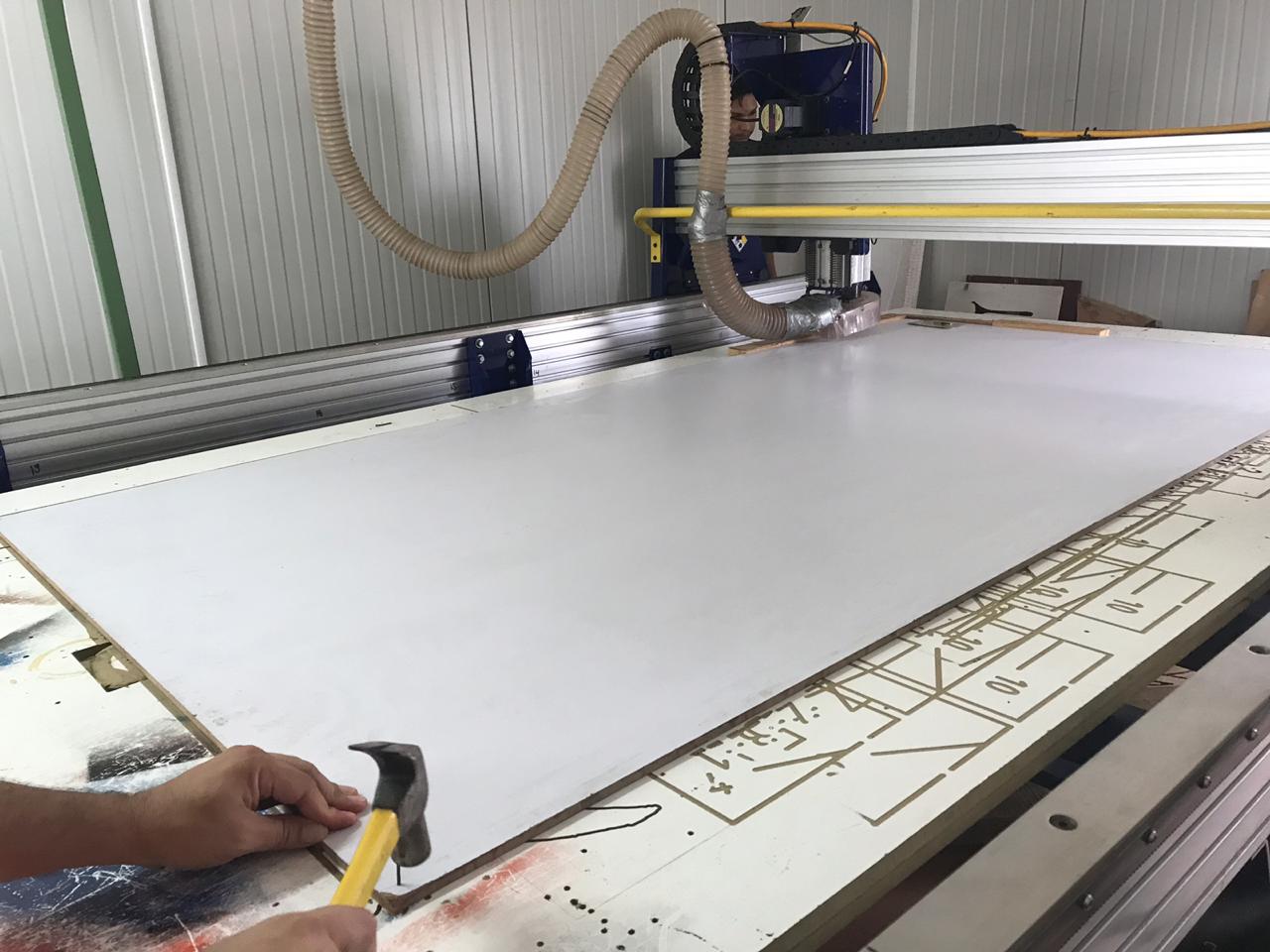
The machine we used to cut our boards was the Shopbot PRSalpha 96-48-8.
Before using the shopbot we had to load the file in the Shopbot software. Then:
-
The board was placed on the Shopbot and nailed in the corners to prevent it from moving
-
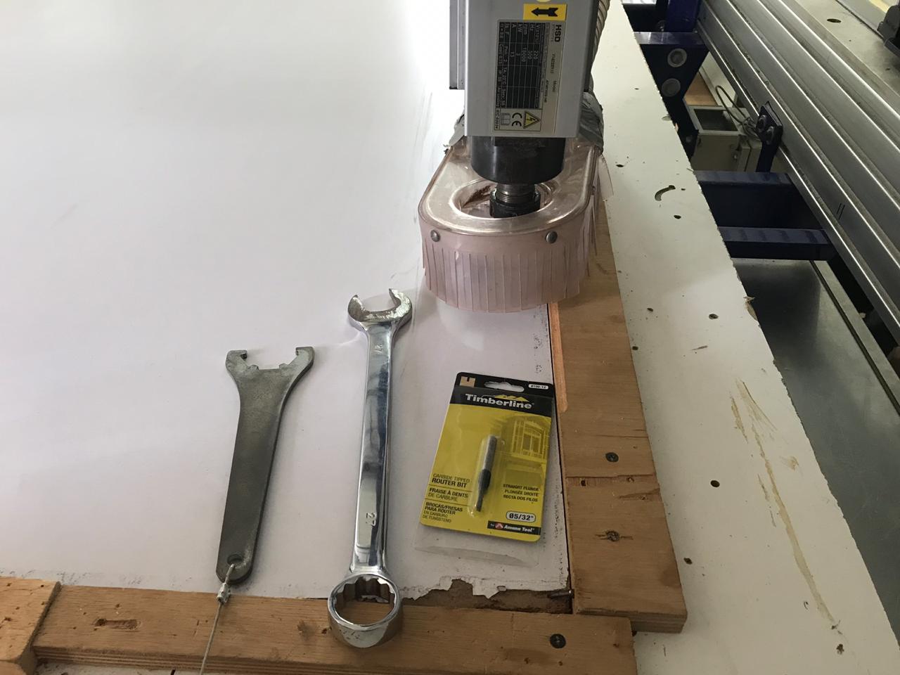
I put in the Bit using a wrench
-
I wore my safety gear (headphone and glasses)
-
I turned on the machine
-
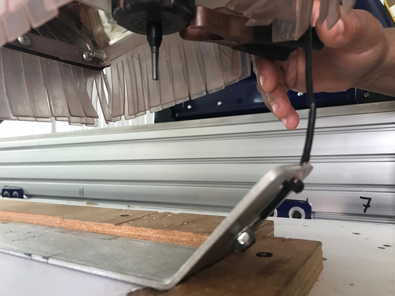
Determined the Z position using the Z-probe
-
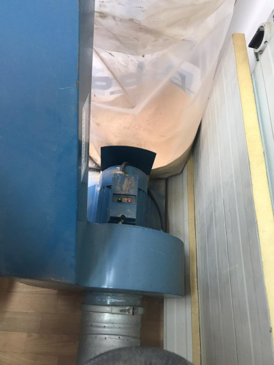
Turned on the vaccuum
-
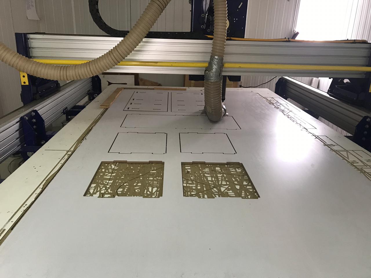
Started to cut the board
-
The first two times the machine cut 3 to 4 bones and stopped. After that it started cutting the bones but didn’t go deep enough. We determined the Z position again but this time we used a sheet of paper instead of the Z -probe. After these changes the board cut without any problems
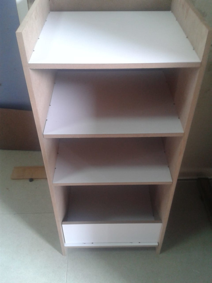
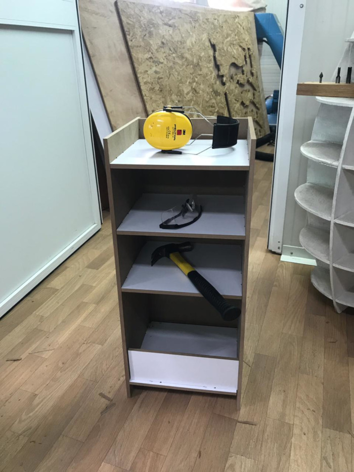
Result
The result of my “Something Big”