4. Computer controlled cutting
Assignment of this week
-
Group assignment
– Characterize your lasercutter, making lasercutter test part(s), making test part(s) that vary cutting settings and dimensions. -
Individual assignments
– Cut something on the vinylcutter
– Design, lasercut, and document a parametric press-fit construction kit, which can be assembled in multiple ways. Account for the lasercutter kerf.
Group Assignment
Vinyl Cutting
I planned to make a sticker for my final project. For those who are not good at drawing like me, I examined a way to easily make various kinds of stickers without drawing pictures.
Drawing sticker
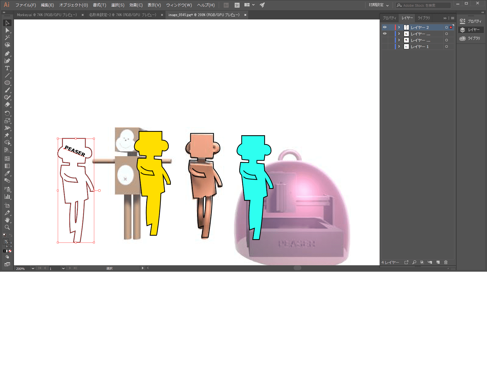
Utilizing the monkey animation I made in the third week, I captured the dancing animation into serialized images using Unity video asset. Then I chose good poses for sticker and extracted the contour using pen tool of the illustrator.
Cutting sticker
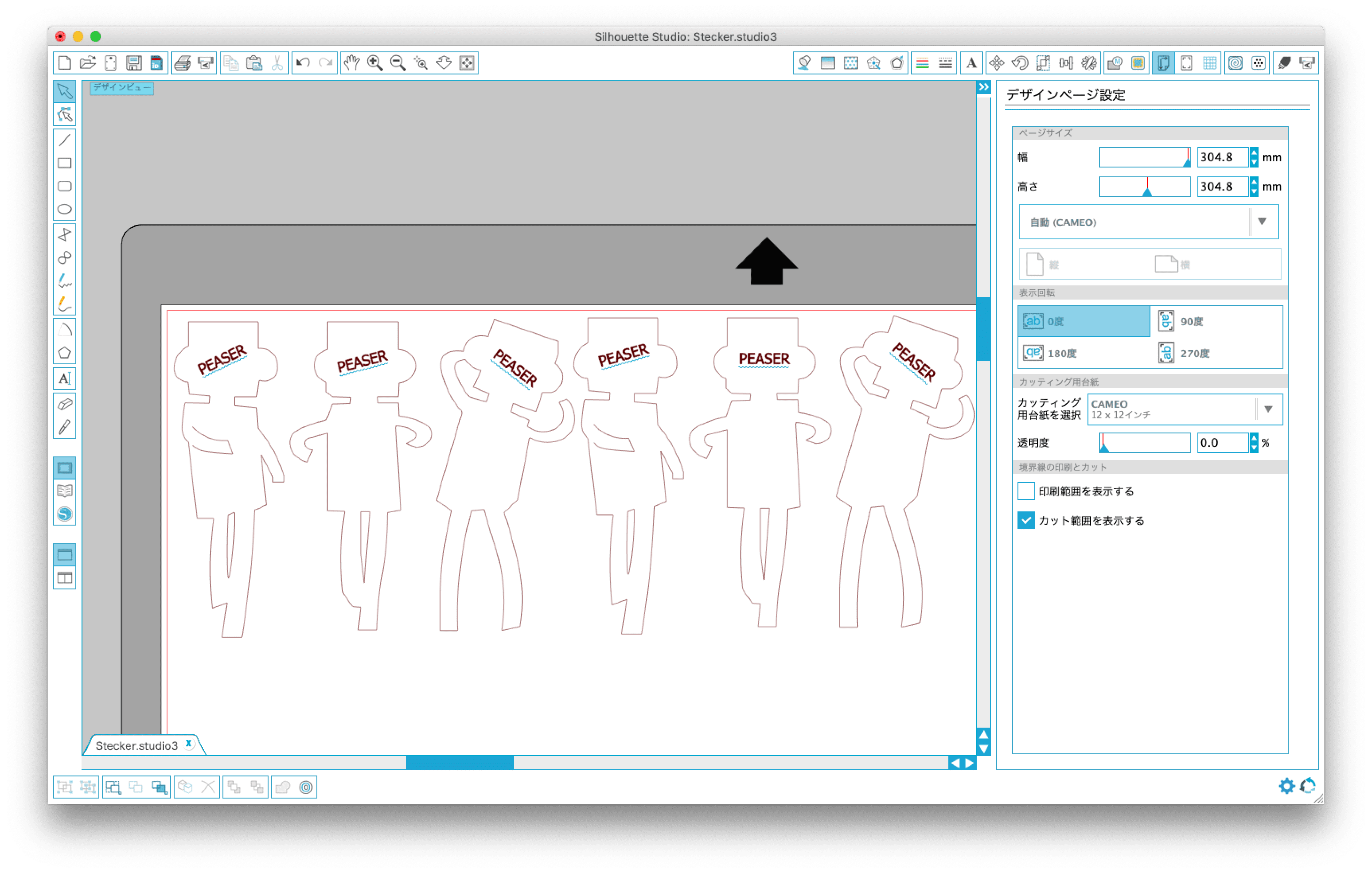
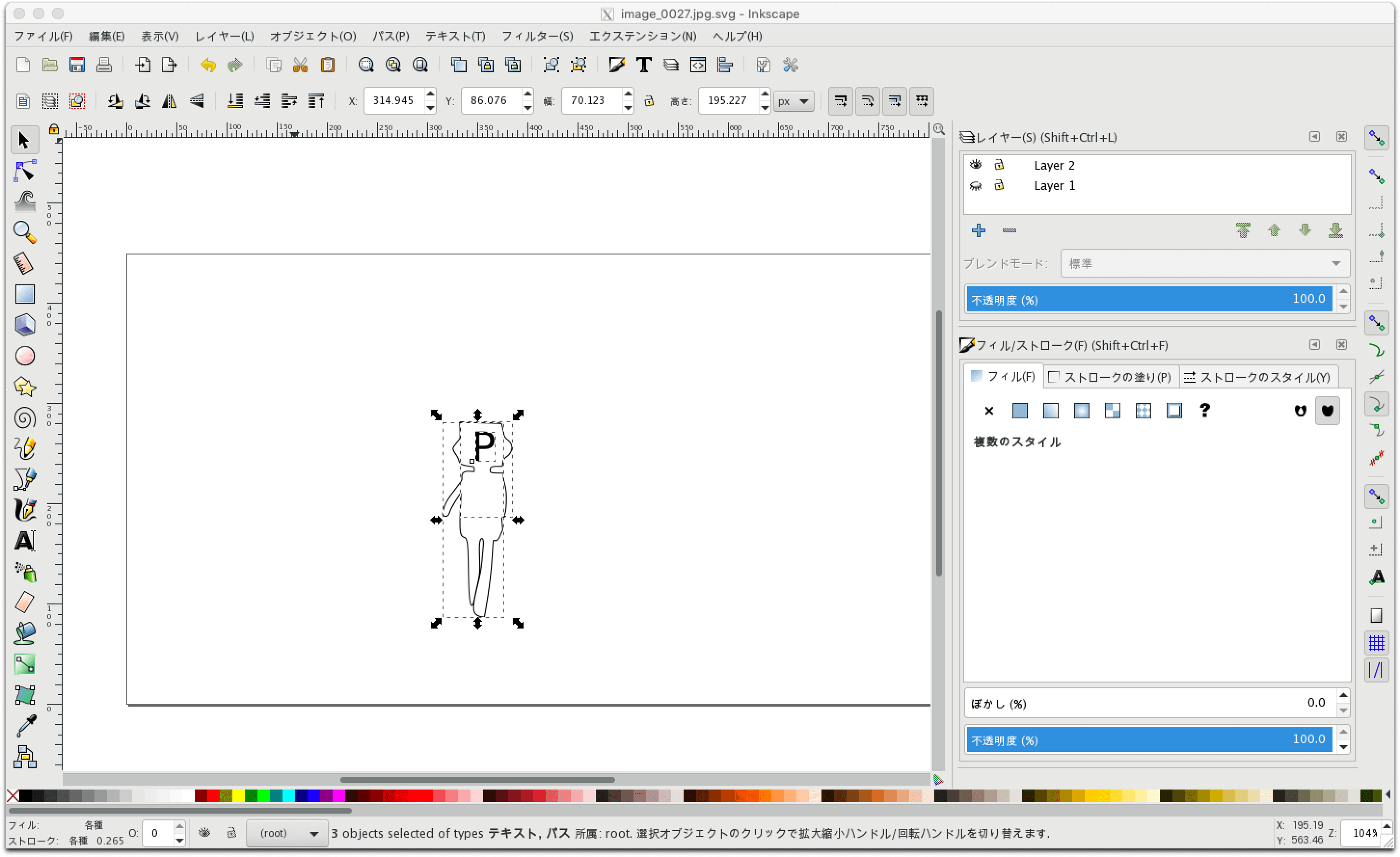
To control the vinyl cutter silhouette CAMEO, I Installed the control software called “silhouette studio” and import the DXF file created by illustrator. However some parameters such as angle was not displayed properly, so I modified using the drawing function of silhouette studio. I also realized that the silhouette studio had the useful function of extracting image outline automatically.
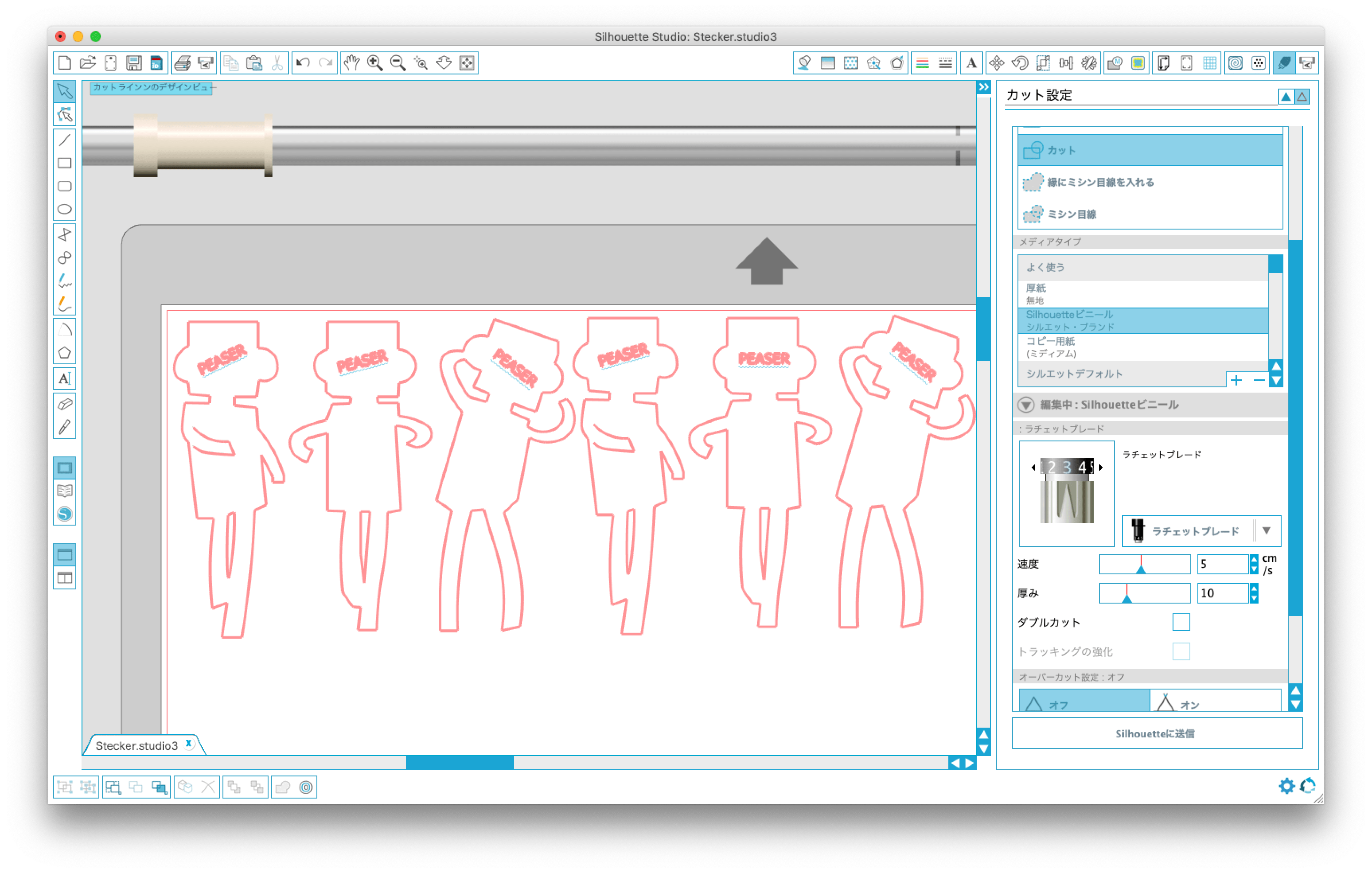
As for cutting parameters, I used following default settings:
cutter blade =3, speed=5, thickness=10
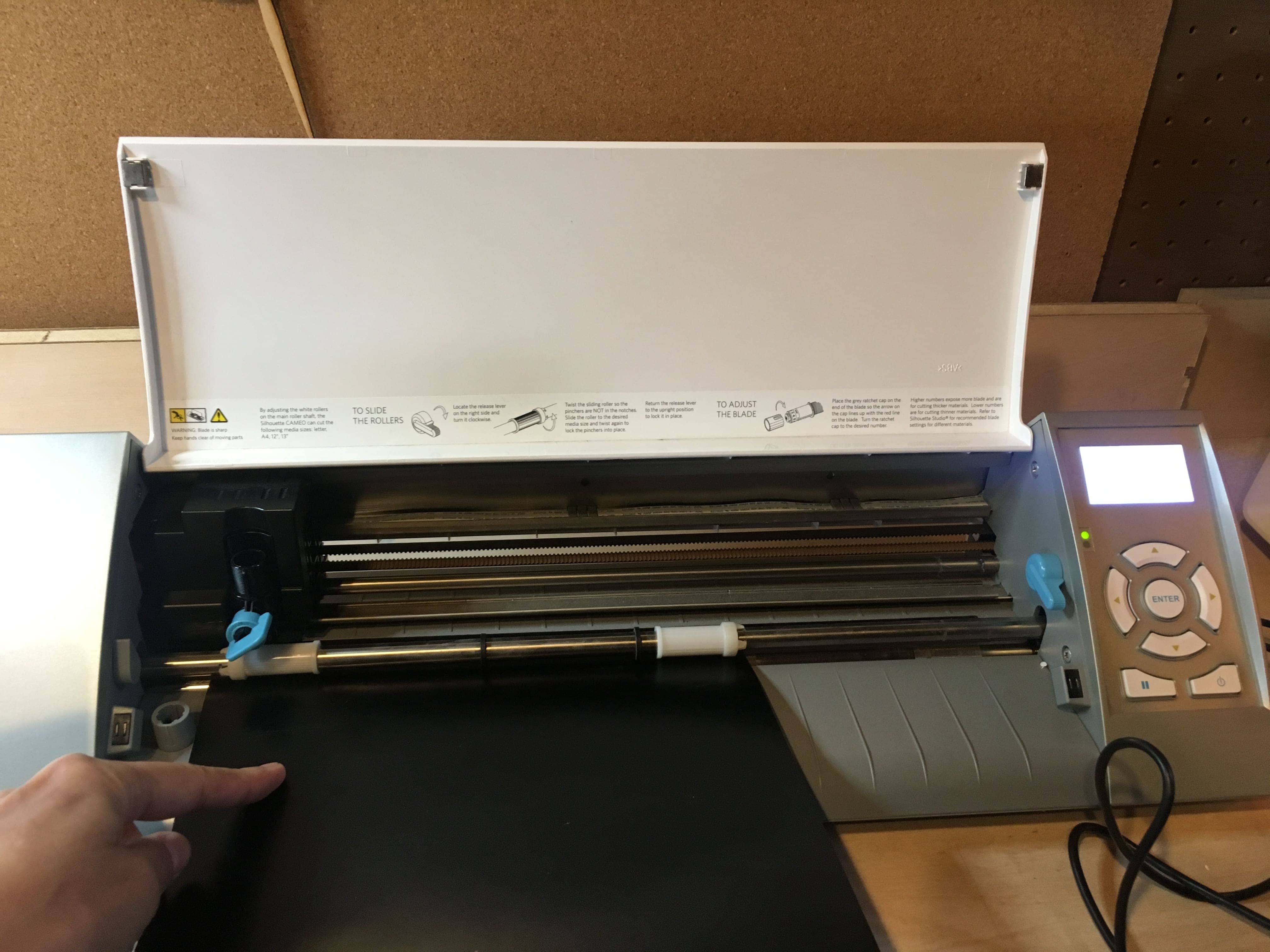
The set of paper seemed easy, but it bent frequently. So I had to carefully place it.
Prior to the cutting, I did test to confirm the parameter and it looked nice.
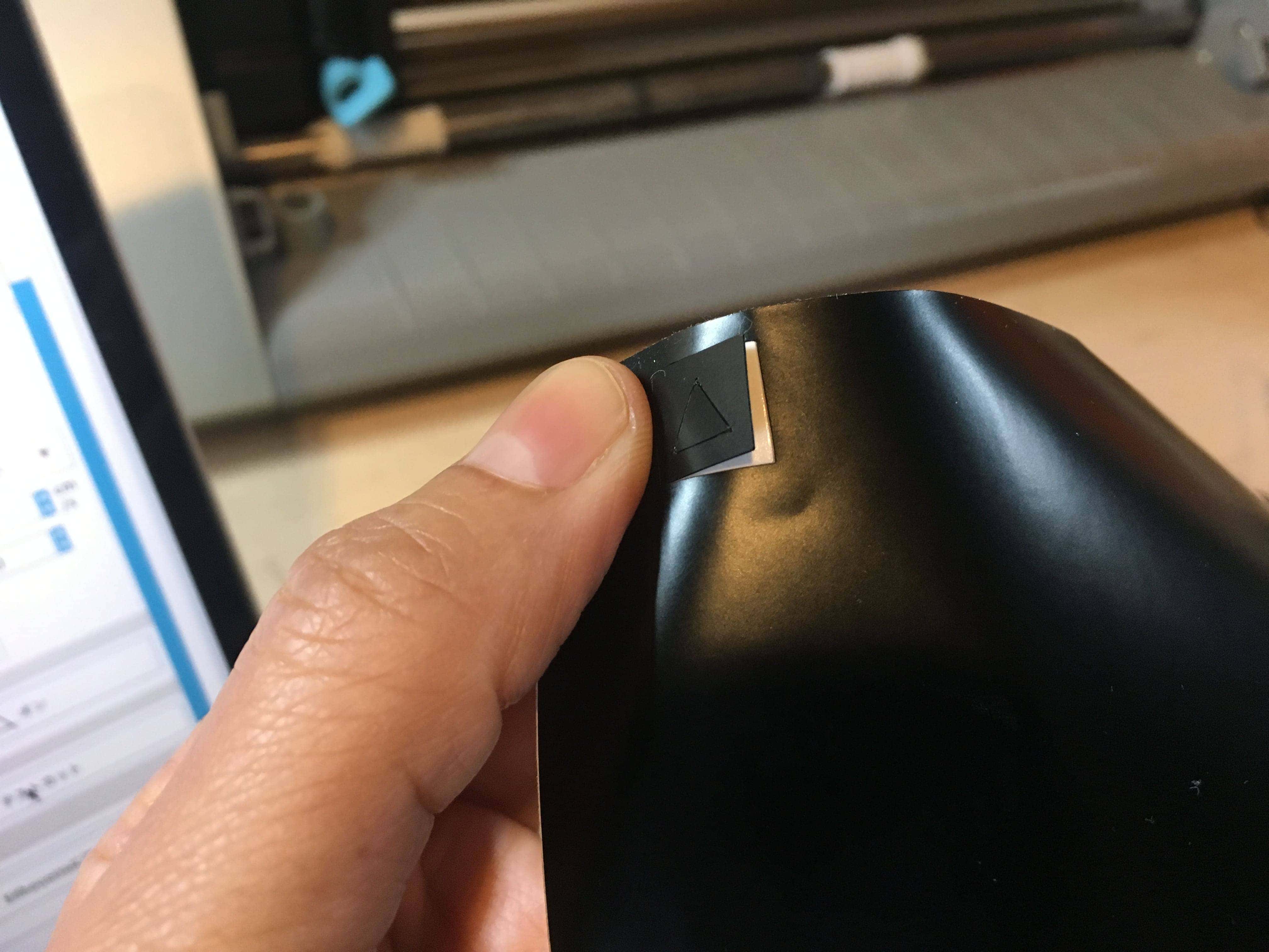
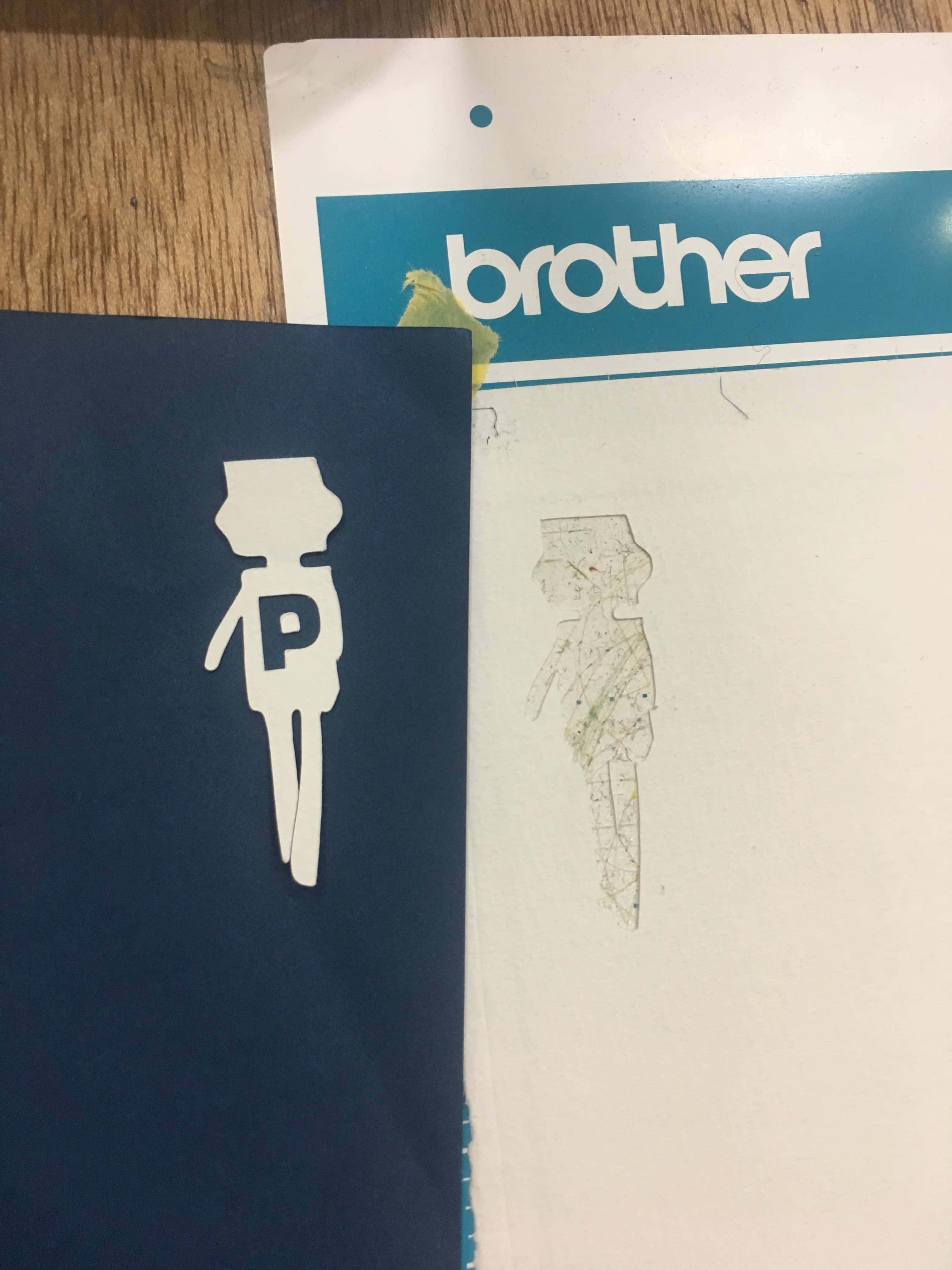
Cute monkey stickers were created. Compared to a laser cutter, operation was simple, and the edge of the material were not scorched.
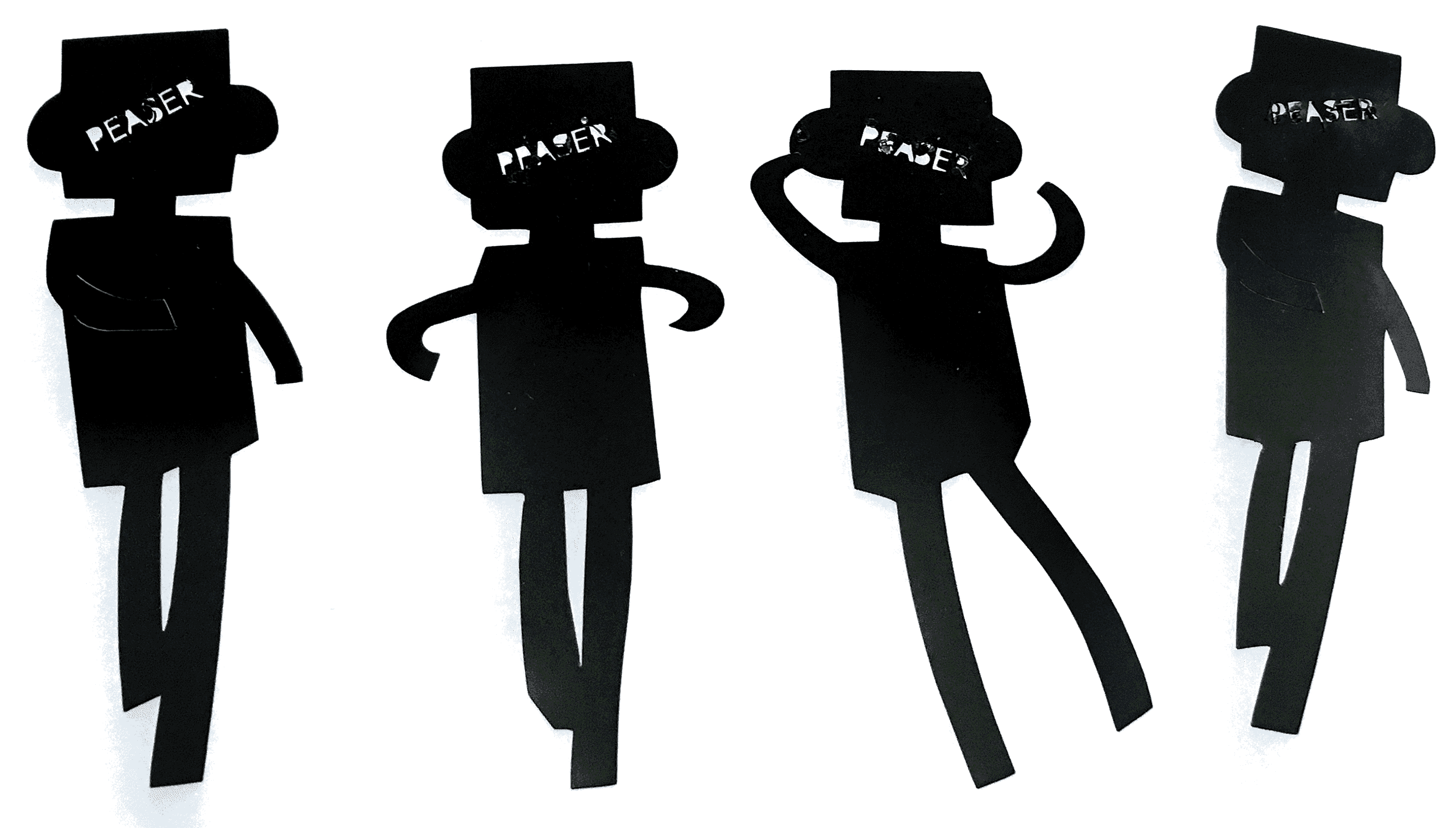
There were two issues.
- The text “PEASER” was not clear. The text size was too small for cutting
- There was a little break on the back side. I think it will be tuned by the cutter blade parameter.
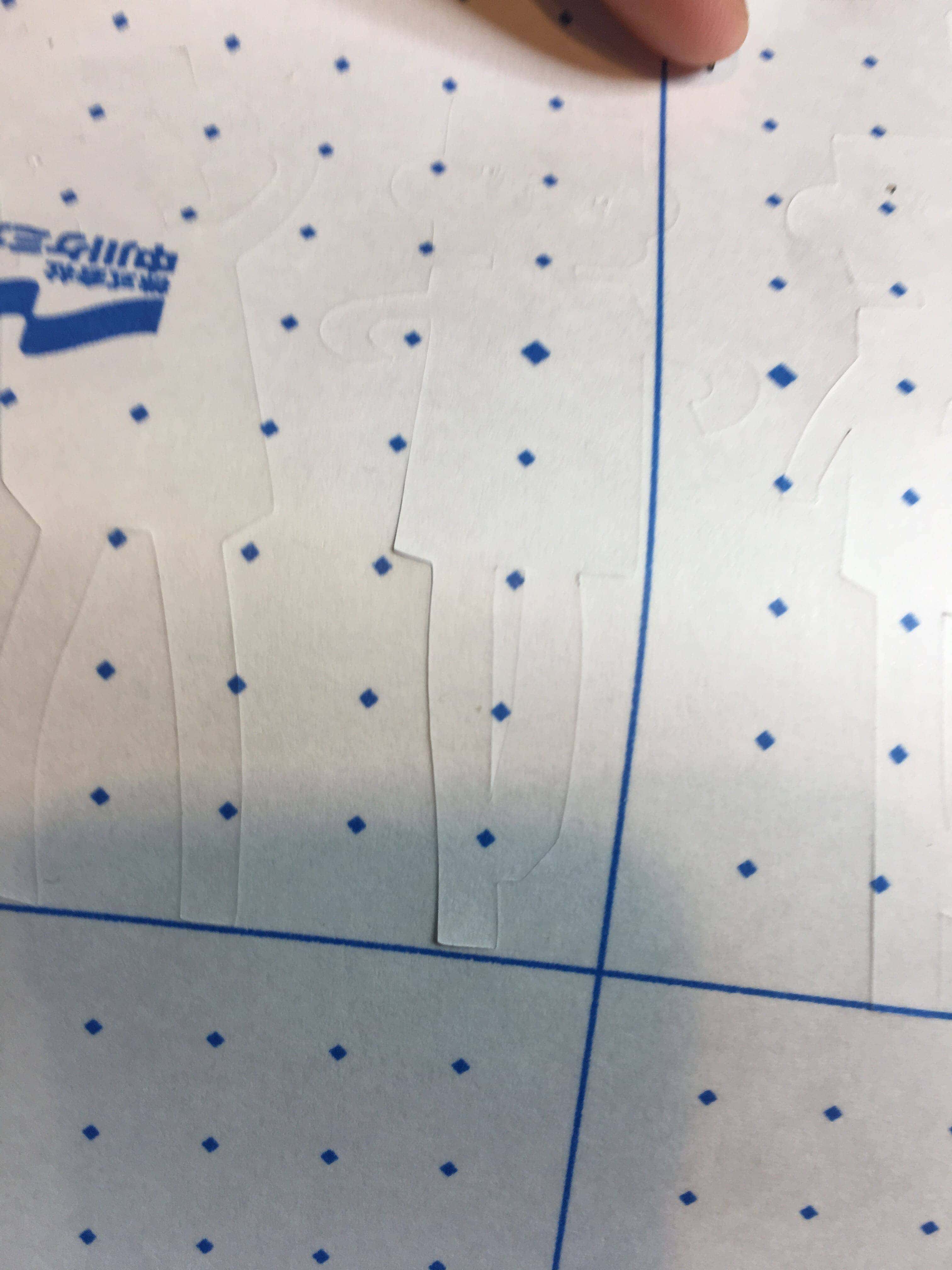
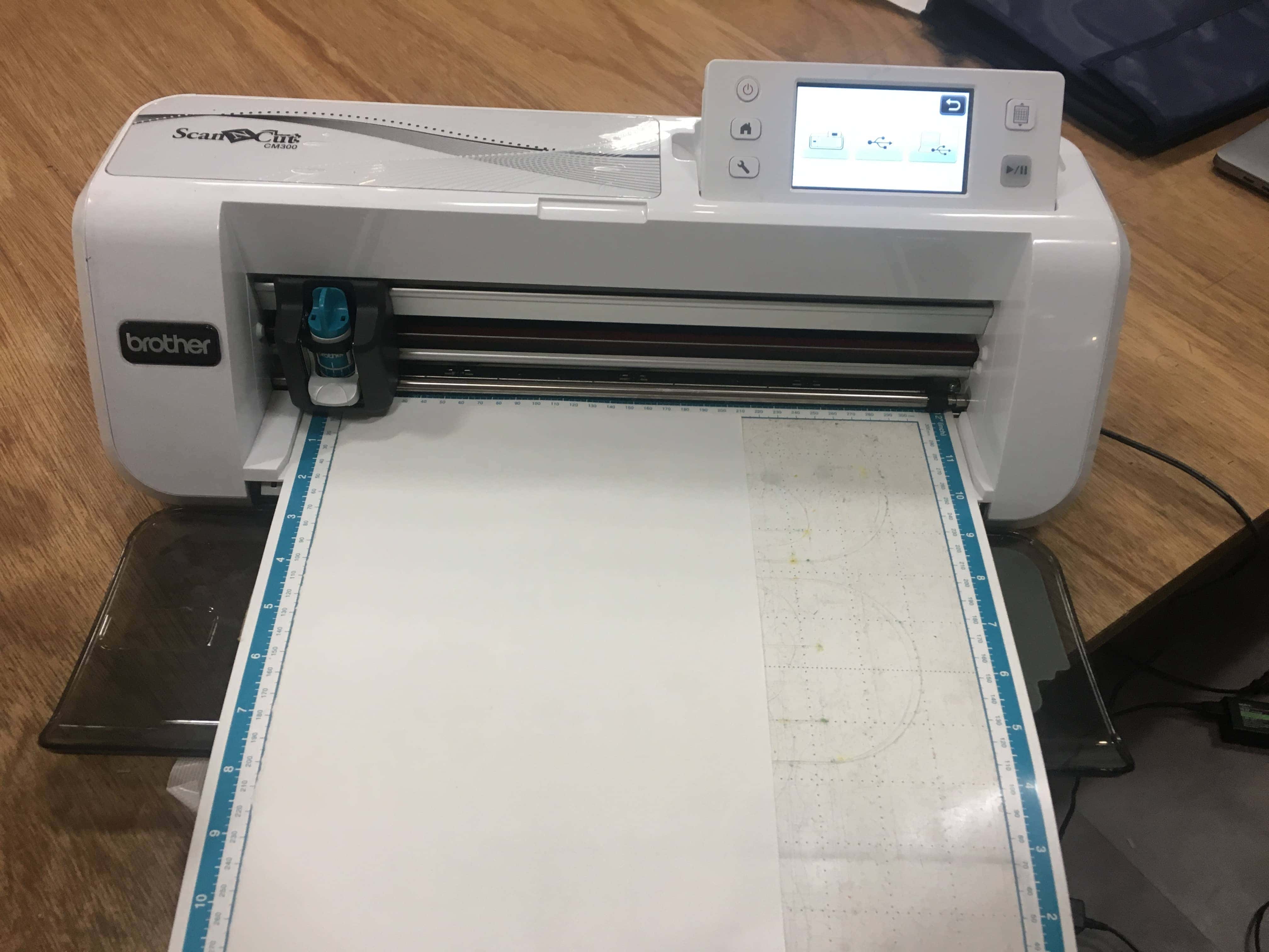
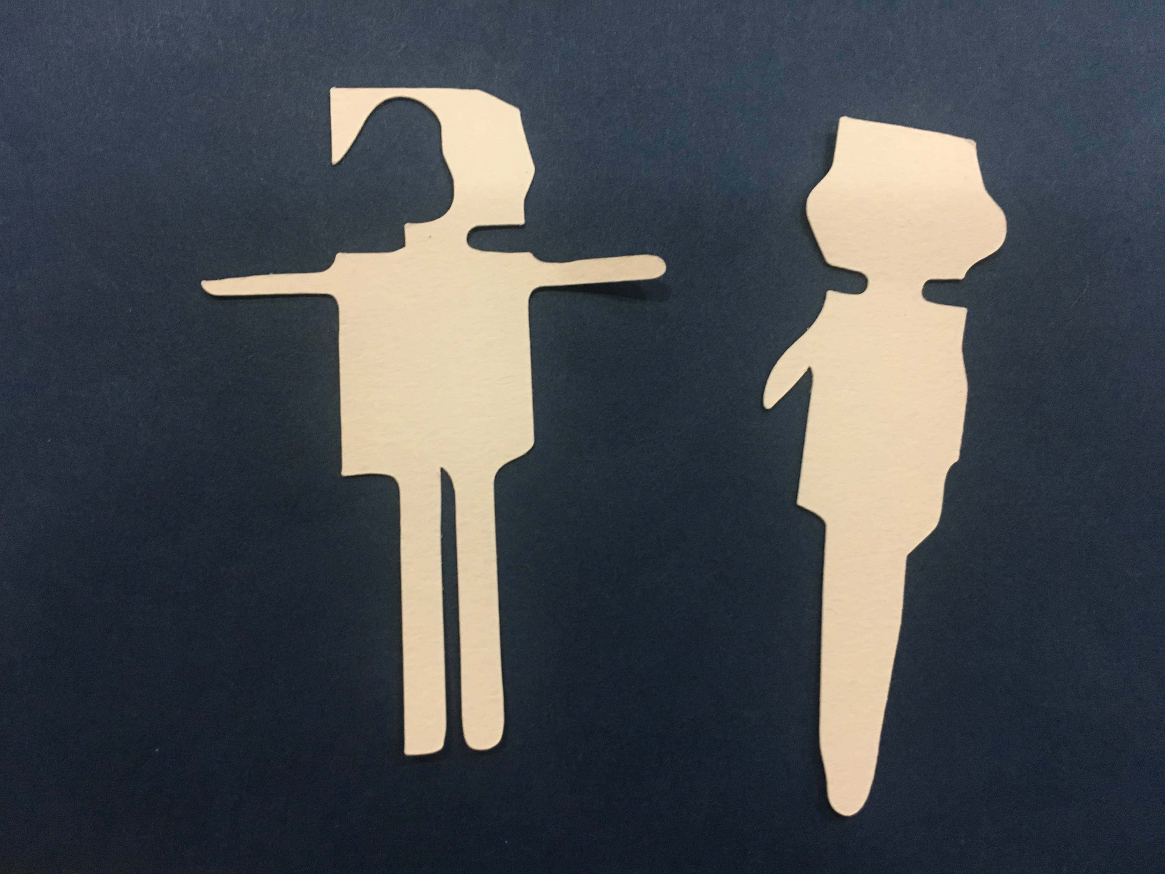
I tried paper cutting with another machine ScanNcut. Though the mechanism was almost same as the cameo, supplied base seat was necessary for paper loading.
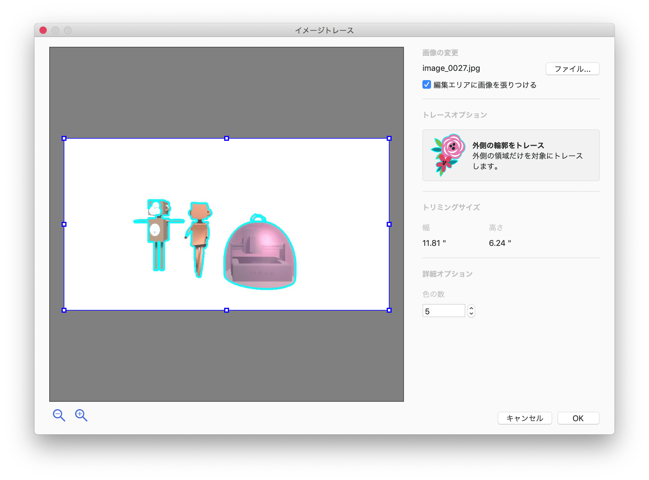
I tried function of the driver that find outline automatically from image. The result was the edge was blunt a little, I prefer manual tool.
Press-fit kit
Concept
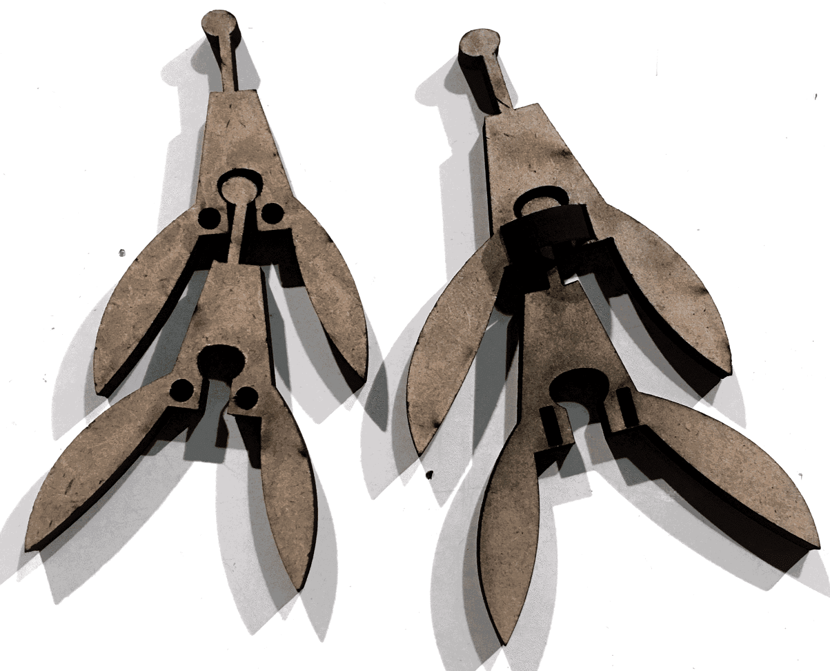
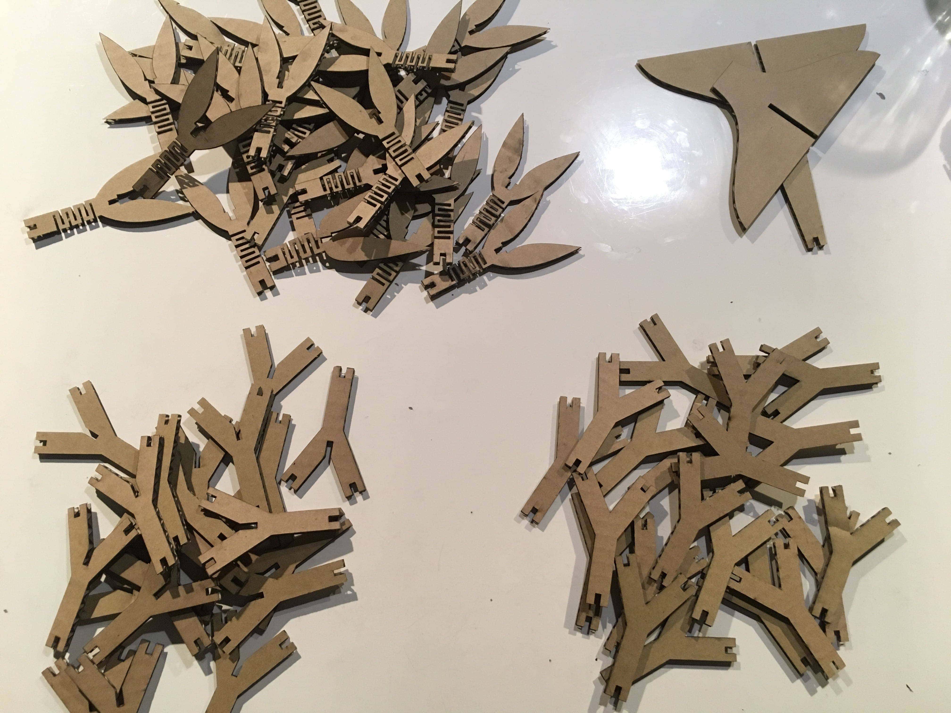
The concept of the press-fit kit is the weeping willow swinging by the wind. First I tried the following joint with round head and press-fit pin parts. I explored more simple one, then reached to utilize living hinge.
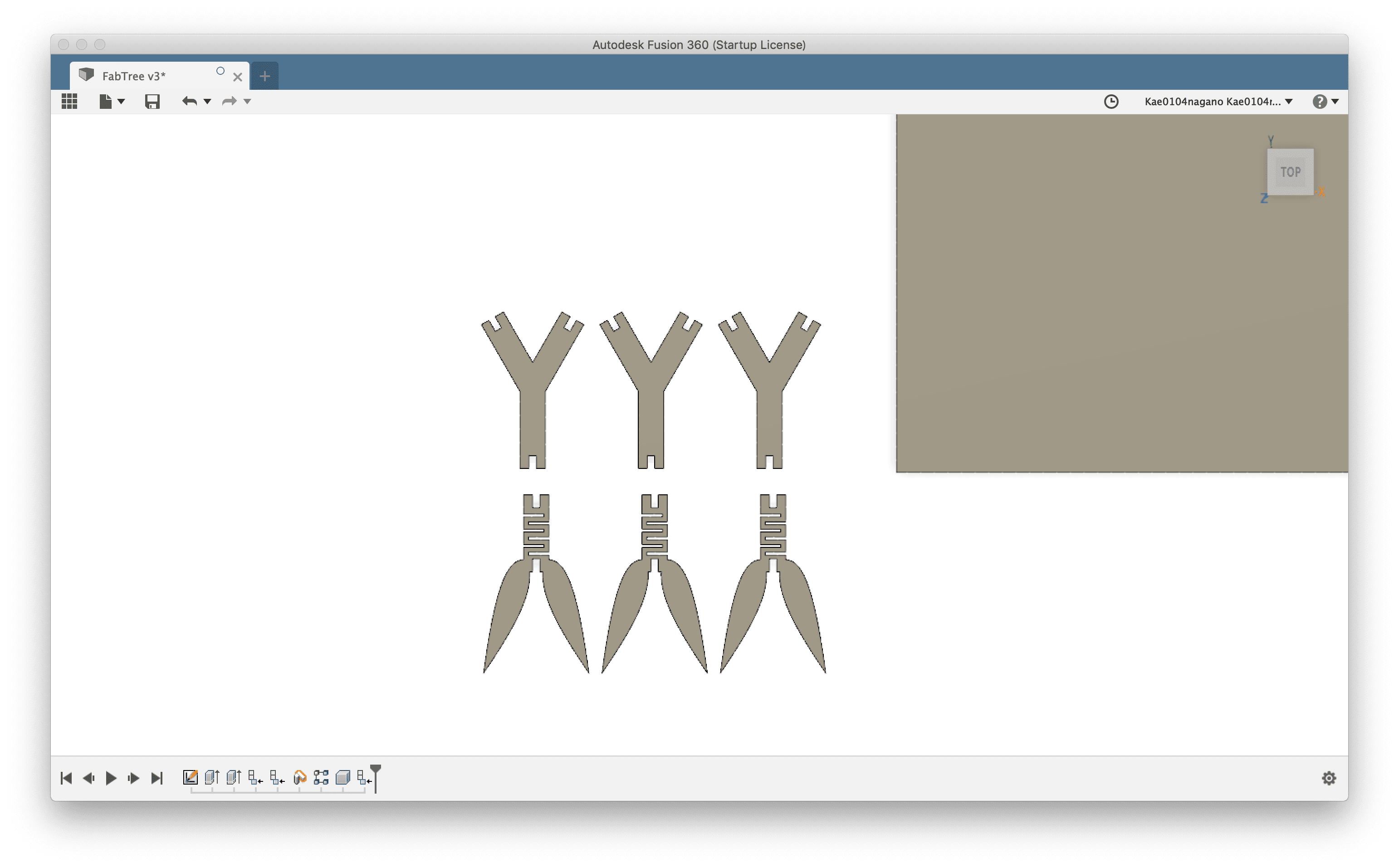
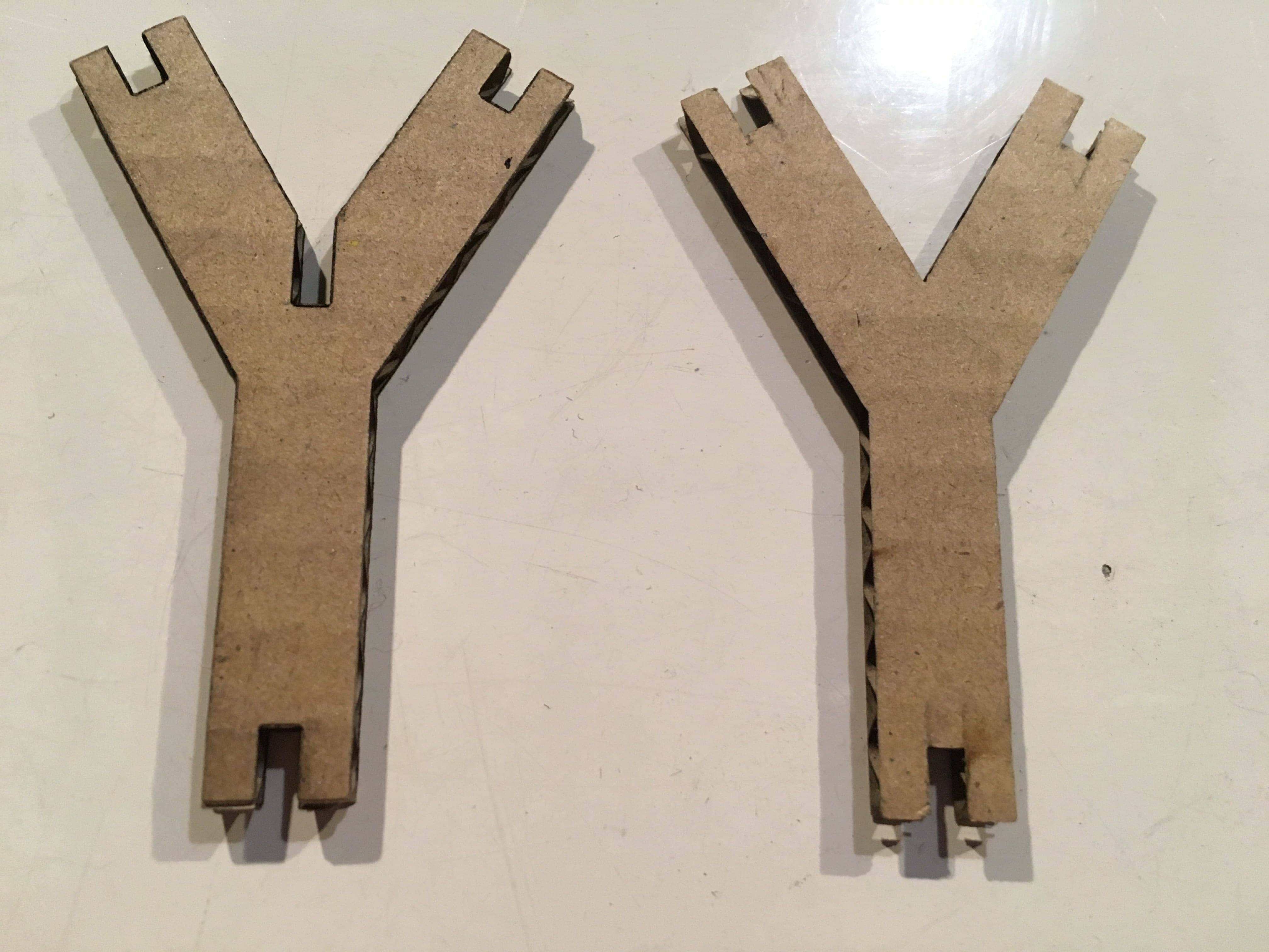
Parametric design
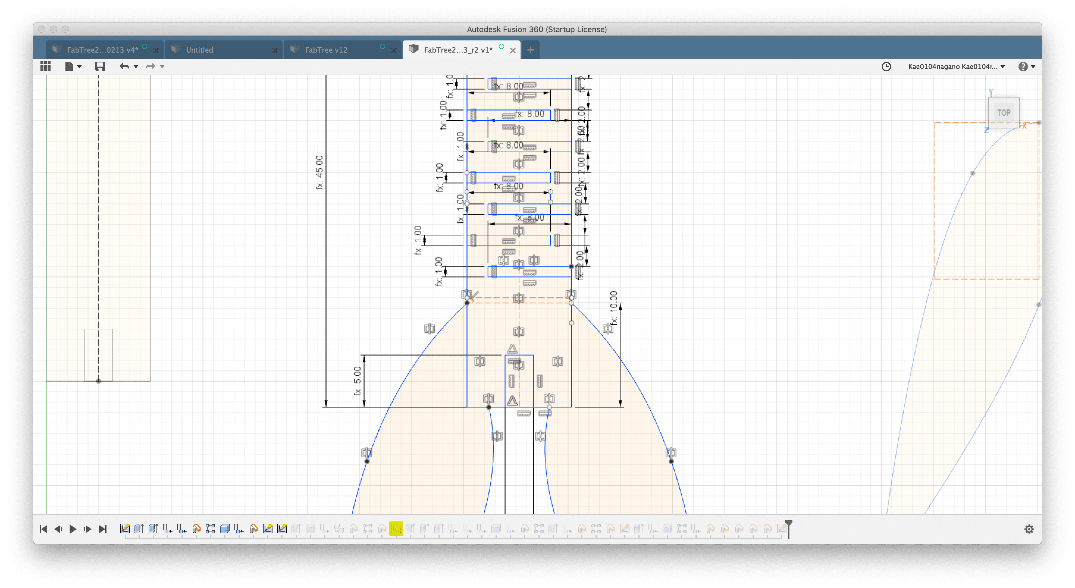
I designed the parametric press-fit kit Using Fusion360. In consideration of changing material and design proportion, the following parameters were defined as user parameters. For the width of the joint tab, I applied the parameter 2.7mm we defined at group work.
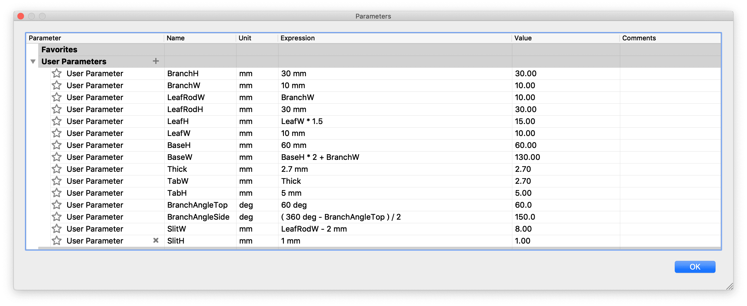
I mainly adjusted the following parameters parametrically.
- Joint width
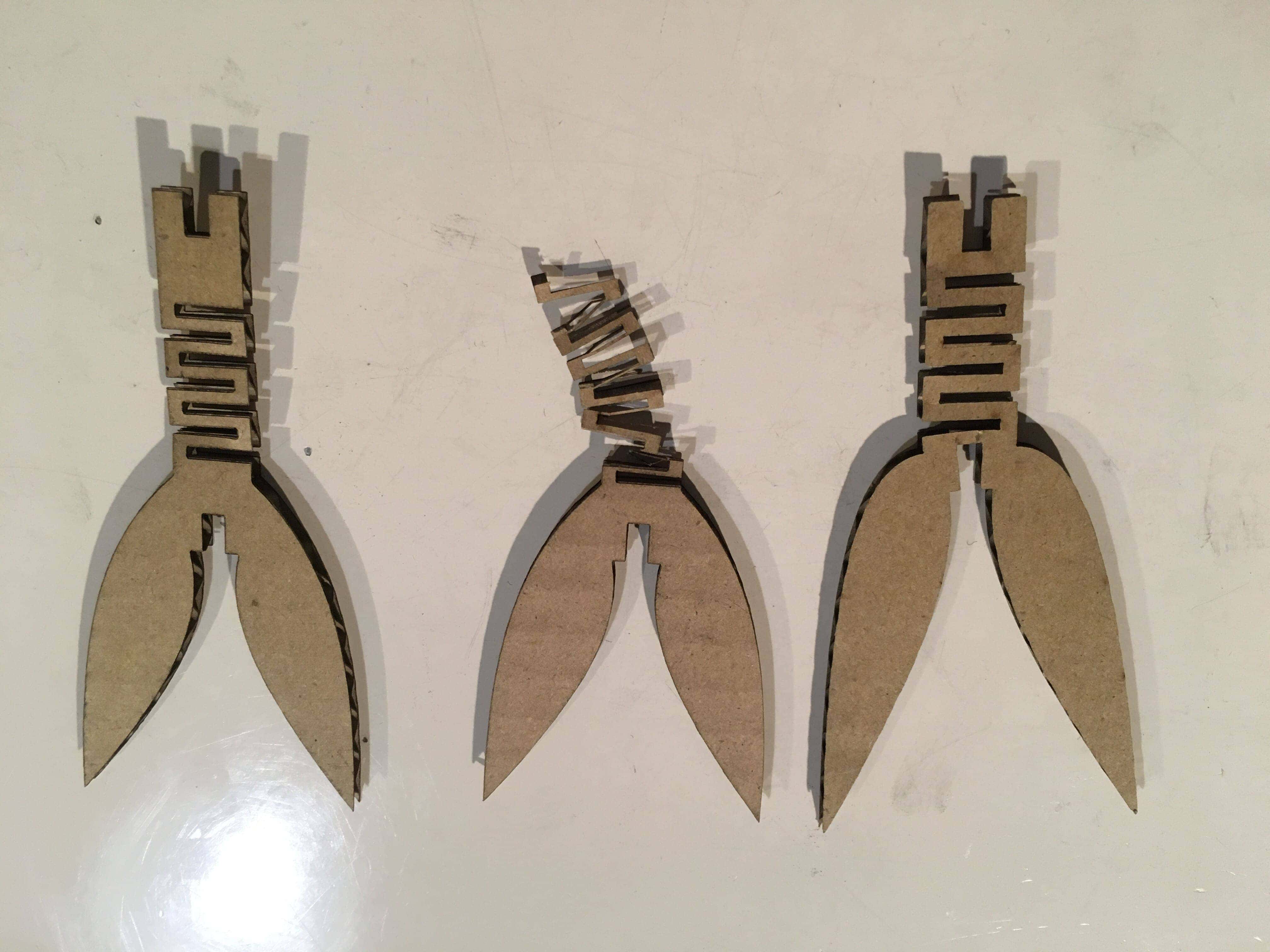
I applied the best width 27mm that found at my group work. However in case of the willow model, it was likely to come off due to the influence of gravity. So I adjusted the parameter from 2.7mm to 2.6mm then finally chose 2.5mm. - Interval of living hinge
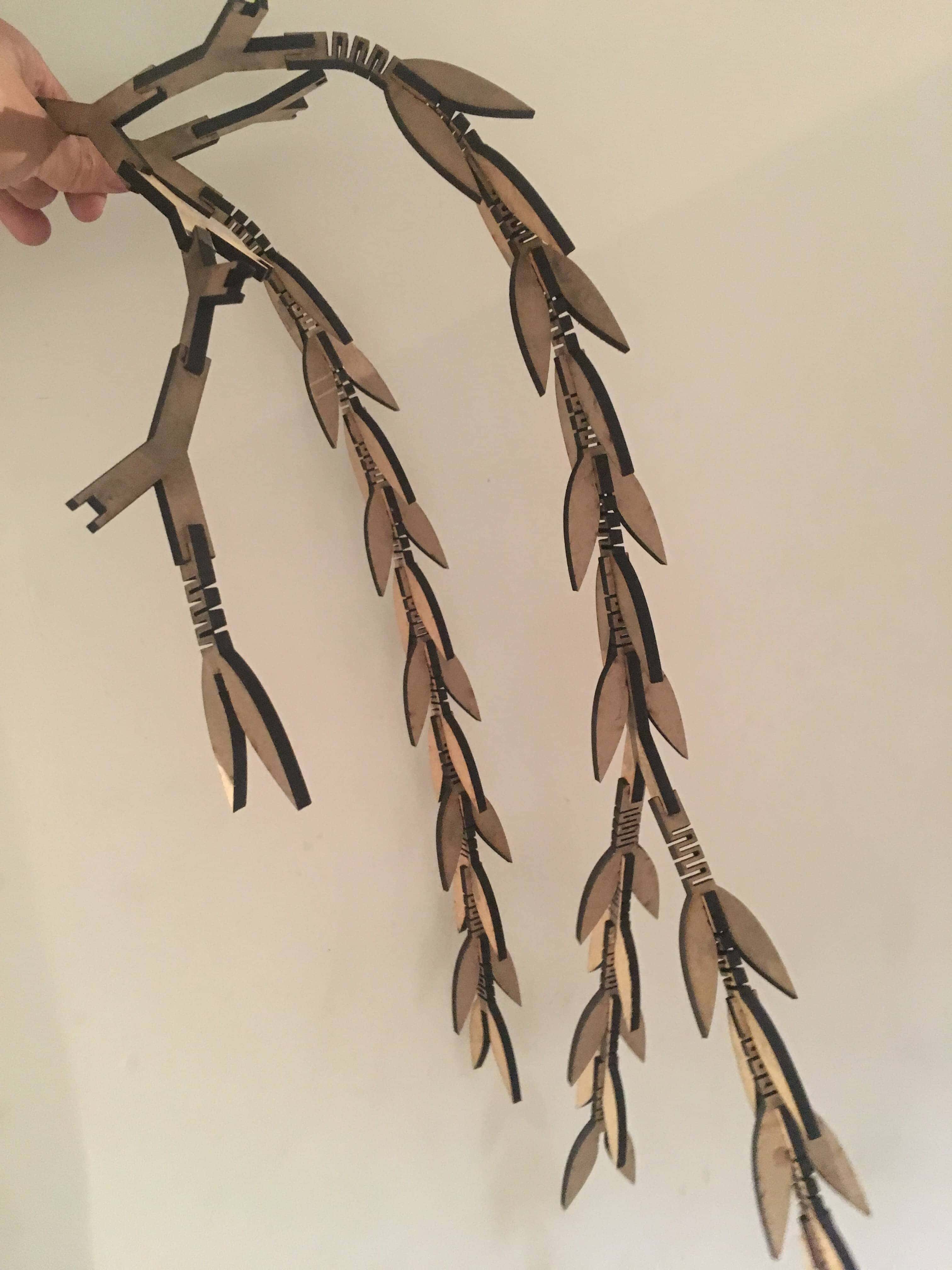
As for the center one below, the width of the living hinge was so narrow that it bent down. So I adjusted the parameter and final result was left leaf.
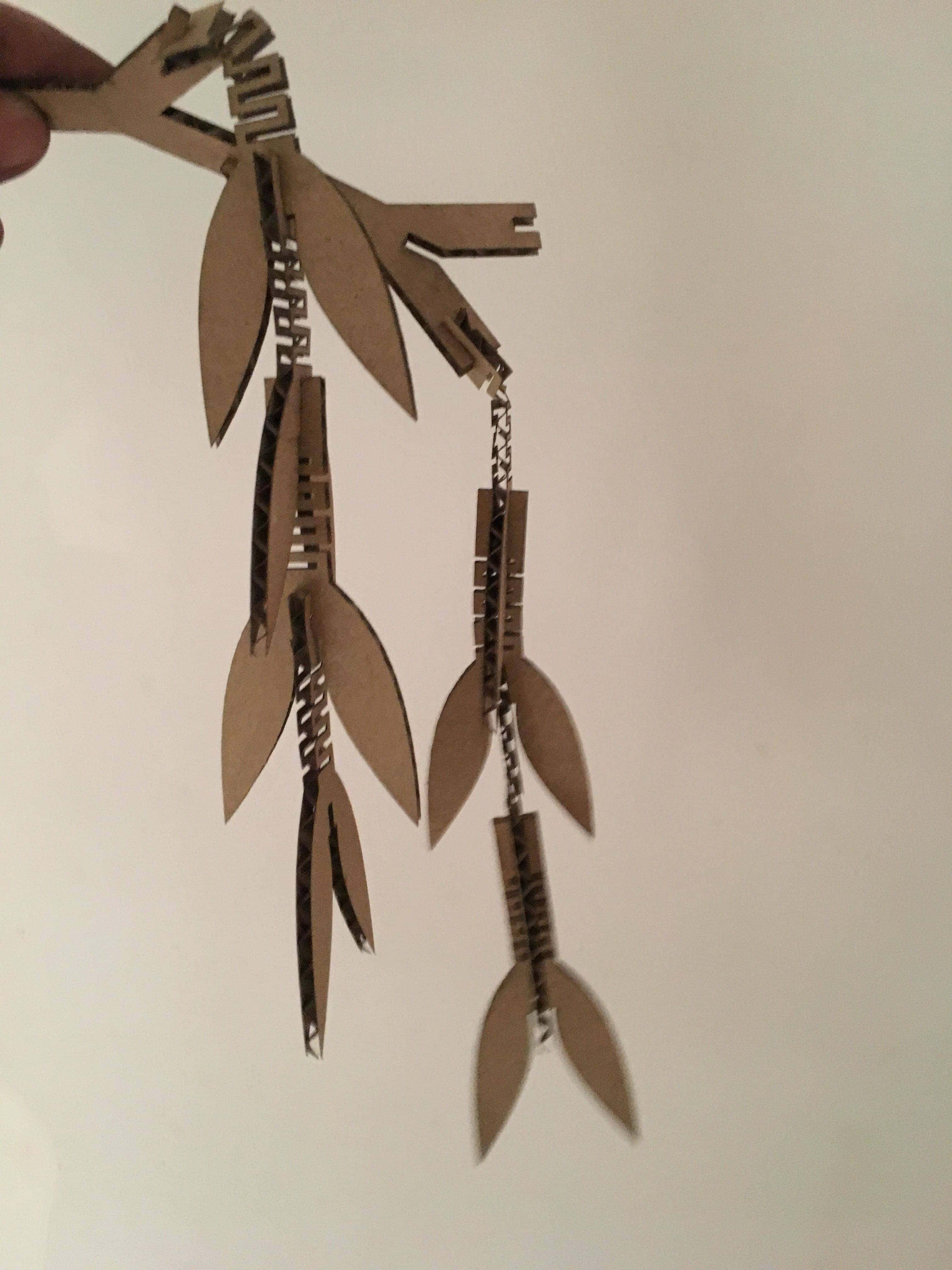
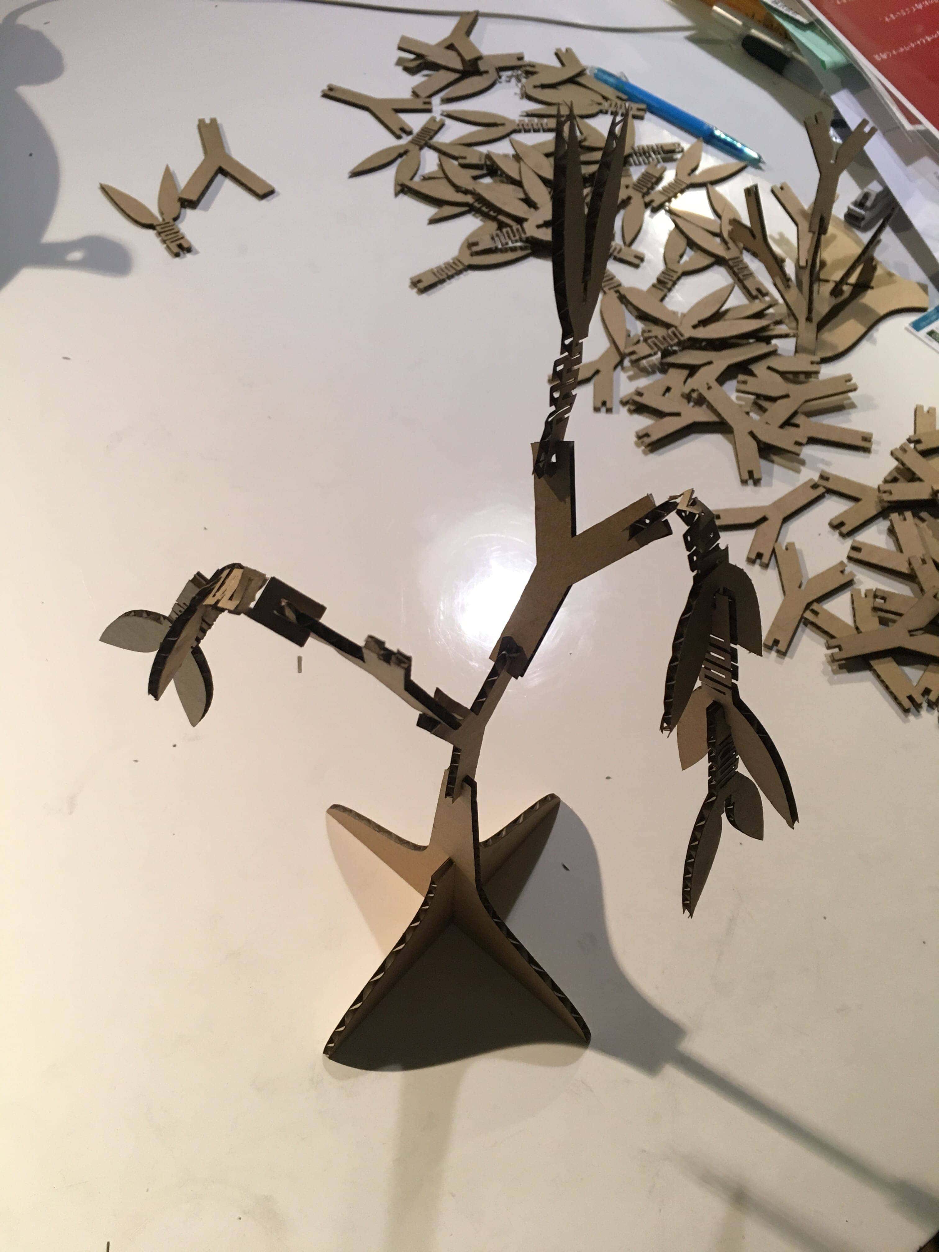

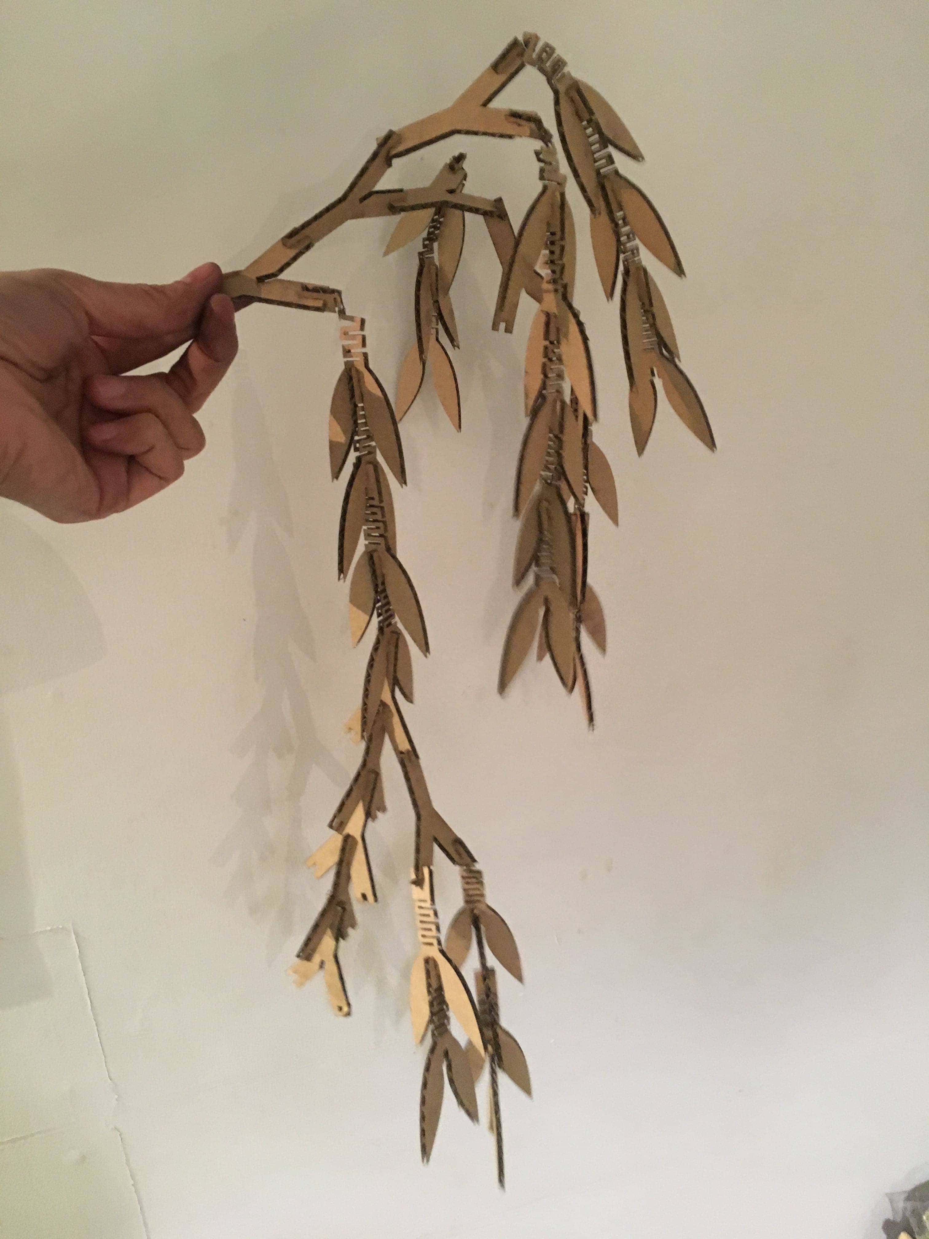

Swinging weeping willow :
Utilizing the parametric design, I also tried 5mm MDF. I investigated the karf first, then adjusted the parameter to 4.7mm.In case of cardboard, there was stress at the top hinge but MDF looked fine. For this type of trial, the parametric design is very useful.
I realized that each laser cutter has its own characteristics. So when making a precise model, parameters should be choose carefully. And the parametric design is really useful for the rapid prototype like this assignment.
Files
- sticker design : Illustrator format
- sticker file : DXF format
- Press-fit design : STEP format
- Press-fit design : DXF format
- Press-fit design : Fusion format(f3d)