11. Input devices
group assignment
Probe an input device’s analog levels and digital signals
individual assignment
Measure something: add a sensor to a microcontroller board that you have designed and read it
| Documentation |
|---|
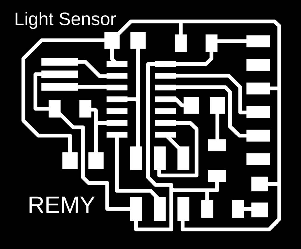
| 1. LightSensorPath.png |
| 2. LightSensorEagleFiles |
| 3. BoatduinoV0.1EagleFiles |
This week, I’m going to make my own PCB with a sensor on it and read the value I get from it.
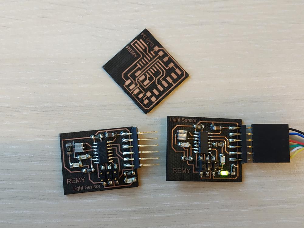
Experimenting with a light sensor
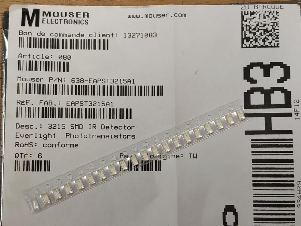
The sensor
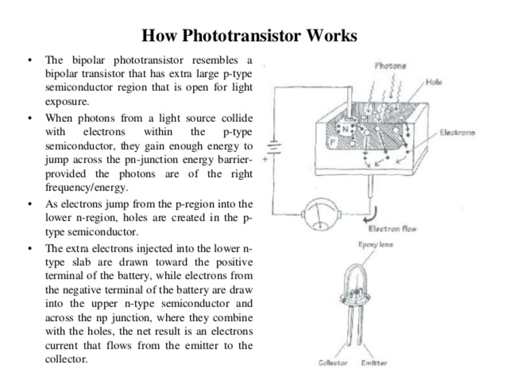
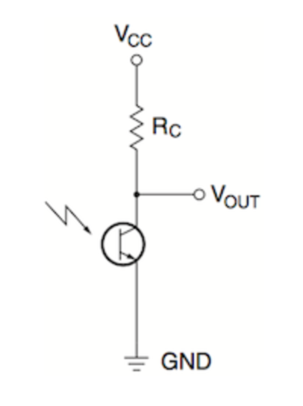
For this first test I’m going to use a light sensor. The sensor I’ve used is a phototransistor. Basically it works as a transistor where the amount of light changes the value of the current going through the base. We have to put a pull up resistor between the collector and the power supply and connect the emmitor to the ground. What we measure is actually the voltage changes between the collector and the ground.
 |
 |
 |
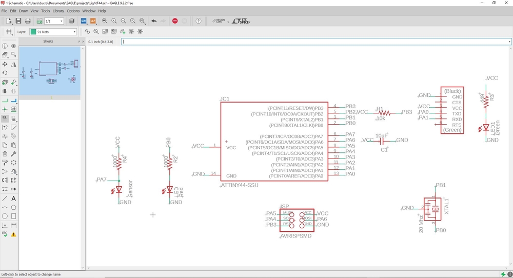
Making the board
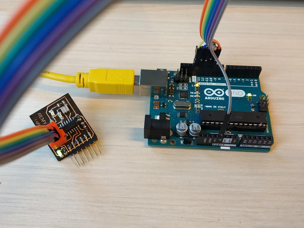
To make the board I needed to have a serial communication and the sensor on a pcb along with the usual connectors and microcontroller.
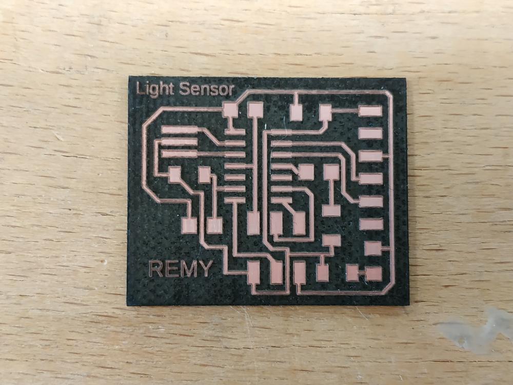
Paths
I’ve taken as a starting point my Hello board, removed the button and the LED to add my sensor. I’ve plugged as well a led in an output to interact with the values of the sensor.
 |
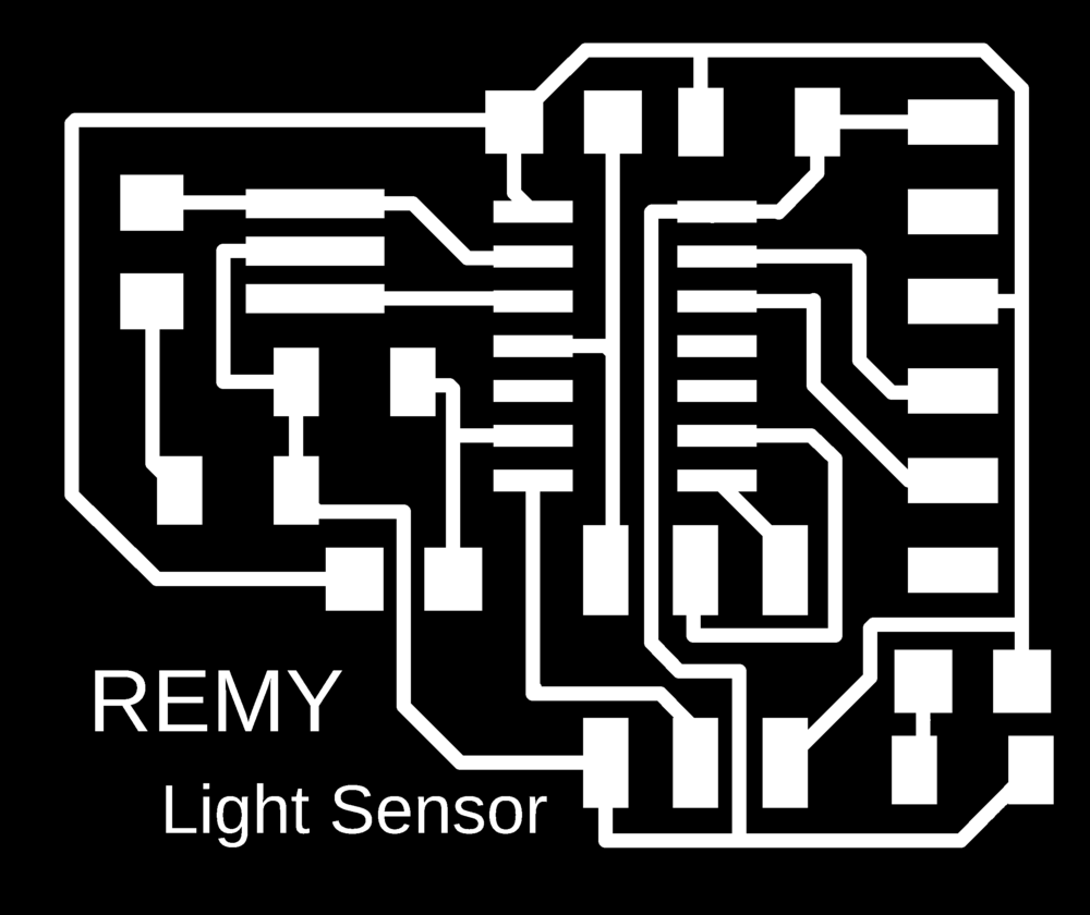 |
NOTE : To use an analog sensor we have to plug it to a pin connected with an ADC, else the microcontroller won’t be able to convert the analog value into a digital one we can use to make our IOT.
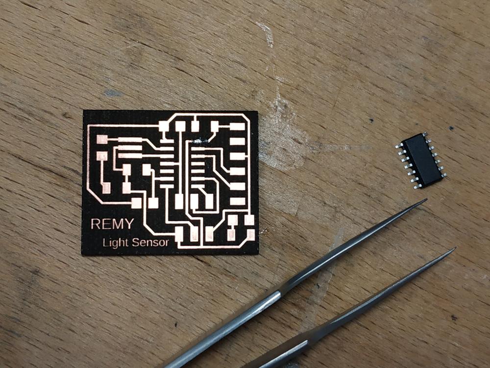
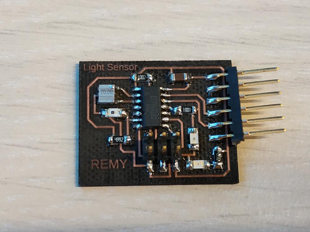
making the PCB
I’ve used the lasercutter to make my PCB. Then soldered the components on it
 |
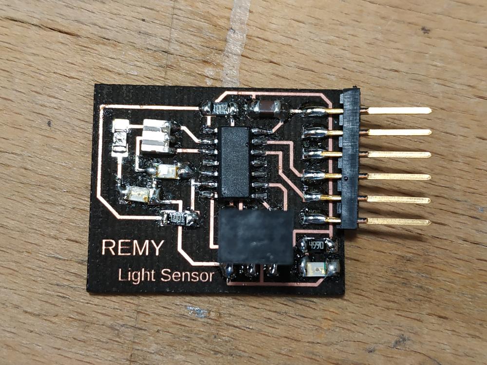 |
NOTE : While making the soldering I’ve found two mistakes in my design. The first one is that I’ve plugged my Output LED to the wrong pin and it connected to the resonator. The second one is that I placed my output LED next the the phototransistor which is not so smart for a device measuring light.
I’ve solved both problems by cutting the path between the resonator and the LED. This way I was still able to use my board to try the serial communication and to read the sensor values.
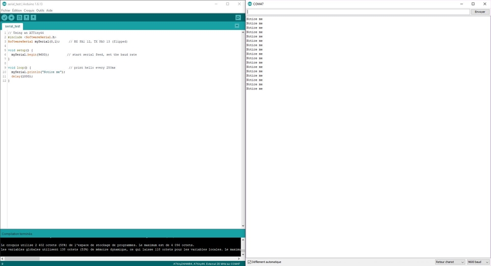
making the code
I then used the arduino IDE to make a simple code just to try the serial connection. To do so I’m using the SoftwareSerial.h library to establish the connection between the ATtiny44 and my computer.
I made a simple code to print values in the serial monitor :
// This code is to verify the serial communication using an ATTiny44

#include <SoftwareSerial.h>
SoftwareSerial mySerial(0,1);         // RX PA1 12, TX PA0 13 (flipped)

void setup() {
    mySerial.begin(9600);             // Set the data speed
    }

void loop() {

    mySerial.println("Notice me");     // Print "Notice me" in the serial monitor
    delay(1000);                       // Wait a second
    }
I then uploaded the code in my board using an arduino as ISP.
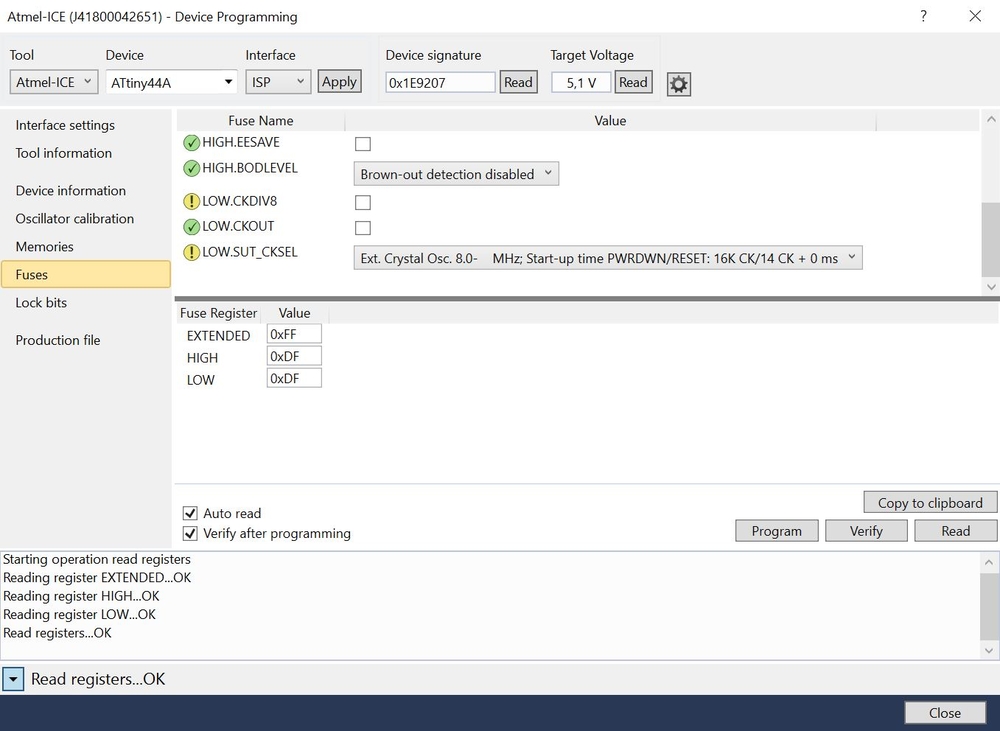
setting the fuses
I used Atmel Studio to set the fuses of the microcontroller. Here are the two fuses I’ve modified :
- I removed the LOW.CKDIV8 which devides the time by height
- I set the LOW.SUT8CKSEL to an external oscillator
Getting the serial connection
Finally I plugged the FTDI connector, opened the arduino serial monitor, set the baud speed and I saw the values come right.
Confident after this test I wanted to see if I could read the value of my sensor.
Getting the sensor value
I’ve modified my code to read the raw values from the sensor and display those in the serial monitor
// Using an ATTiny44
#include <SoftwareSerial.h>
SoftwareSerial mySerial(0,1);     // RX PA1 12, TX PA0 13 (flipped)

// Pin Configurations
    const int SENSOR = A7;     //Sensor probed in PA7 which means A7 for arduino
    int sensorValue;


    void setup() {

    mySerial.begin(9600);
    mySerial.println("Serial Connection ok");
    }

    void loop() {
    sensorValue = analogRead(SENSOR); // Give to sensorValue, the value you receive
    mySerial.println(sensorValue); // Print in monitor serie this value

    delay(250); //Wait
    }
Once the program was uploaded right, I got the values of my sensor.

NOTE : The ADC used in this micocontroller is a 10 bits ADC which means it converts in 2^10 possibilites (1024). Here we can see that the sensor varies from 900 to 1023. To have a greater range I have to adjust the resistor I’ve connected to the collector of the phototransistor.
As per the gain formula : G = Rc/Re
Here the value of the Re resistor depends on the amount of light going through the component. However the bigger the value of Rc, the bigger the Gain. I changed my resistor from a 10K to a 49.9K and this time I had all the range available from the ADC (from 0 to 1023).

Making the final PCB
I’ve modified my PCB design to put an LED on an output pin and place the sensor away from the LEDS.
 |
 |
Then I made the PCB.
 |
 |
Testing the PCB
I’ve modified my code to had the possibility to switch On and Off an LED to a certain threshold.
// Using an ATTiny44
#include <SoftwareSerial.h>
SoftwareSerial mySerial(0,1);     // RX PA1 12, TX PA0 13 (flipped)

// Pin Configurations
    const int SENSOR = A7;     //Sensor probed in PA7 which means A7 for arduino
    const int LED = A2;        // LED probed in PA2 which means A2 for arduino
    int sensorValue;


    void setup() {
    pinMode(LED,OUTPUT);
    mySerial.begin(9600);
    mySerial.println("Serial Connection ok");
    }

    void loop() {
    sensorValue = analogRead(SENSOR); // Give to sensorValue, the value you receive
    mySerial.println(sensorValue); // Print in monitor serie this value

if(sensorValue < 800){ //If the sensor value is above 800
    digitalWrite(LED,HIGH); //Switch on the LED
    delay(250); //Wait
}
else{ //If the sensor value is below 800
    digitalWrite(LED,LOW); // switch off the LED
    delay(250); //Wait
}
}
Here’s a video of it functioning. As I put my finger above the sensor it reduces the amount of light passing through the sensor and it switches on the LED.
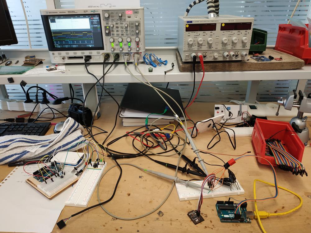
Oscilloscope observations
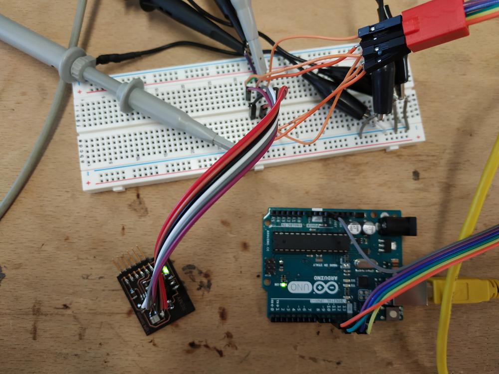
The ISP connection
First, I wanted to see the ISP data going into my PCB as I upload the code.
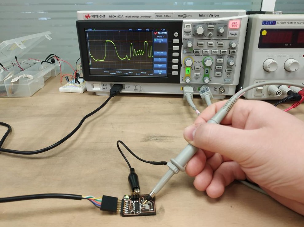
I used a breadboard to simplify the connections between the ISP connector, my ISP and the ocilloscope. Then I probed four pins of my ISP (RESET, MISO, MOSI, SCL).
 |
 |
In our oscilloscope we have a function to analyse the ISP / I2C communication and visualize the hexadecimal code transfered to the board.
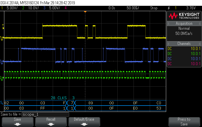
NOTE : Here we can see the MISO (yellow), MOSI (blue) and CLOCK (green). We can clearly see that the clock is here to set time and that MISO is an echo of MOSI.
Measuring the analog input signal
I probed the signal I measured with my sensor and by approaching a light to the sensor I was able to see on the oscilloscope the voltage changes.
 |
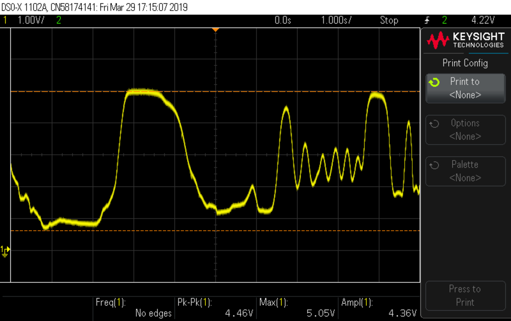 |
NOTE : I didn’t find a way to probe the output of the ADC to see how the signal was transformed by the microcontroller. That would be cool to see both signals.
Measuring the digital output signal
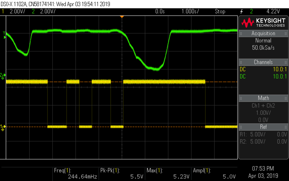
I probed at the same time the analog input and the digital output to see how the microcontroller used the analog input to make a digital output.
Experimenting with an accelerometer
Making it work with an Arduino uno
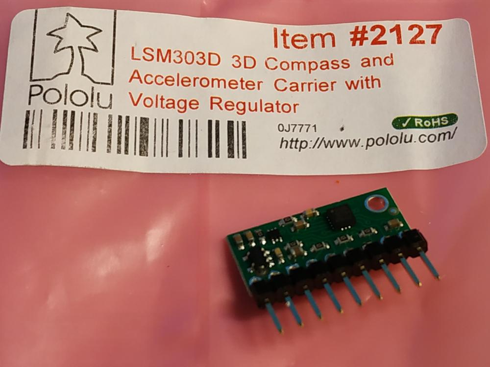
For my final project, I’m going to navigate my boat, so I need to know how it moves. The accelerometer is a good sensor for that. In the lab we have a LSM303D on a pcb from Polulu.
 |
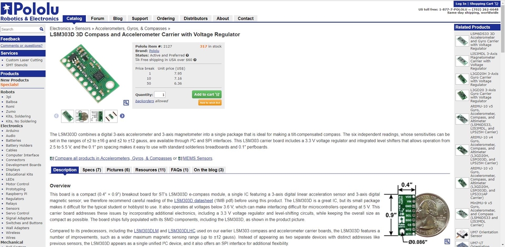 |
The PCB with the sensor uses a I2C communication to transmit datas to the master PCB. I’ve uploaded the LSM303 library and uploaded the following code to the arduino.
#include <Wire.h>
#include <LSM303.h>

LSM303 compass;

char report[80];

void setup()
{
  Serial.begin(9600);
  Wire.begin();
  compass.init();
  compass.enableDefault();
}

void loop()
{
  compass.read();

  snprintf(report, sizeof(report), "A: %6d %6d %6d    M: %6d %6d %6d",
    compass.a.x, compass.a.y, compass.a.z,
    compass.m.x, compass.m.y, compass.m.z);
  Serial.println(report);

  delay(100);
}
In the serial monitor I was able to get values from the sensor which changed acccording to the movement of it. Here’s a video of it working.
Making my boatduino board
Making the board
To go further, I’ve decided to make my own version of arduino board but made for my need : the boatduino.
I went through this tutorial and designed my own version.
I made a breadboard version where I managed to blink an LED.
I then decided to make my own board with the following settings :
- That can act like an arduino and run using the arduino environment
- That can enable serial connection through FTDI
- That can make digital output
- That can have a I2C connectivity
- That can run an anlog input
I needed to add an ISP connector to burn the boatlooder.
I’ve been through some though times in Eagle to find the proper libraries with all the components I was using for my board. After some failures I’ve been through the sparkfun libraries for Eagle which got everything I needed.
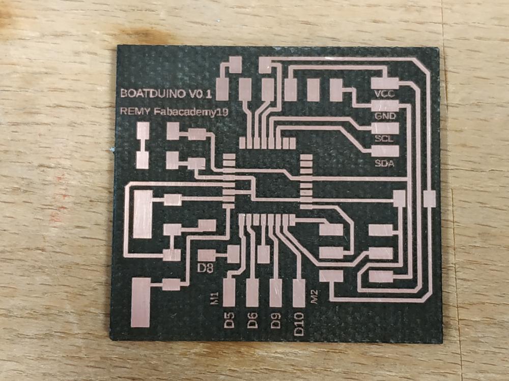
I then designed my board.
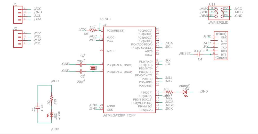 |
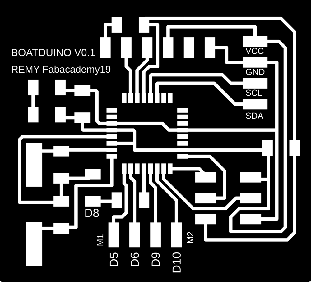 |
I made it using the lasercuter and soldered the components :
 |
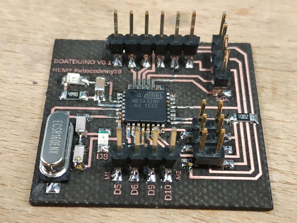 |
Soldering the microcontroller wasn’t easy and I spent lots of time checking with the multimeter and the oscilloscope if I had all the good connections.
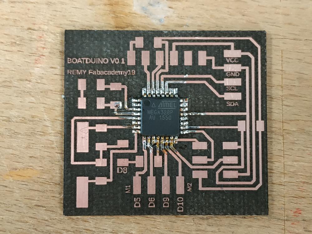 |
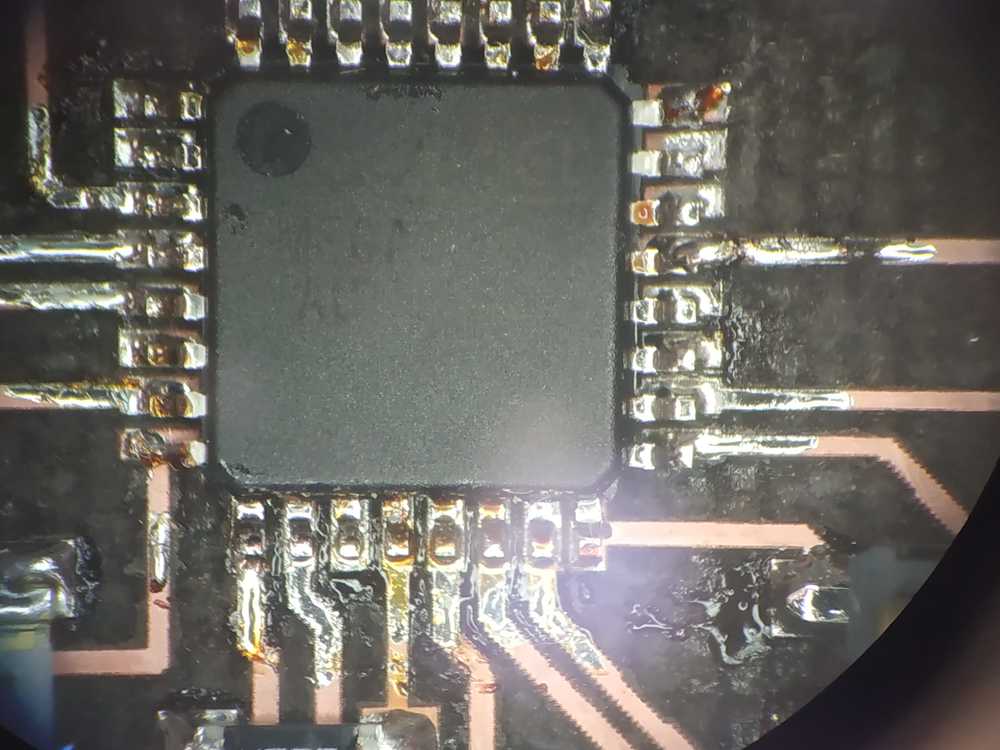 |
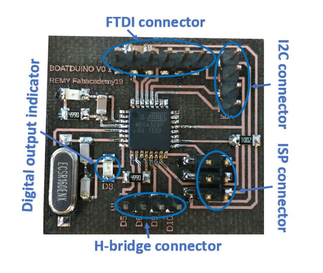
Here are the different features of my board.
When all the components where ready I plugged my arduino as ISP and burnt the boatlooder using arduino IDE.
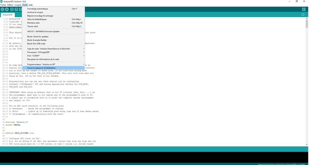
Burning the bootloader makes the board act like an arduino which means I could upload in it my code in arduino language. As everything went on well I continued with testing my board.
Testing the board
Digital output
In my design I put a LED and a current limiting resistor on the PD5 output (digital output 5 in the arduino world). I’ve uploaded a blink code and it worked.
// the setup function runs once when you press reset or power the board
void setup() {
  // initialize digital pin 8 (pb) as an output.
  pinMode(8, OUTPUT);
}

// the loop function runs over and over again forever
void loop() {
  digitalWrite(8, HIGH);   // turn the LED on (HIGH is the voltage level)
  delay(1000);                       // wait for a second
  digitalWrite(8, LOW);    // turn the LED off by making the voltage LOW
  delay(1000);                       // wait for a second
}
NOTE : I upload my code using an FTDI connector which means I do not need the ISP connection or any side device to upload my codes.
Serial communication
To test the serial communication, I’ve used the same code I used with the ATTiny44 :
#include <SoftwareSerial.h>
SoftwareSerial mySerial(0,1);         // RX PA1 12, TX PA0 13 (flipped)

void setup() {
    mySerial.begin(9600);             // Set the data speed
    }

void loop() {

    mySerial.println("Notice me");     // Print "Notice me" in the serial monitor
    delay(1000);                       // Wait a second
    }
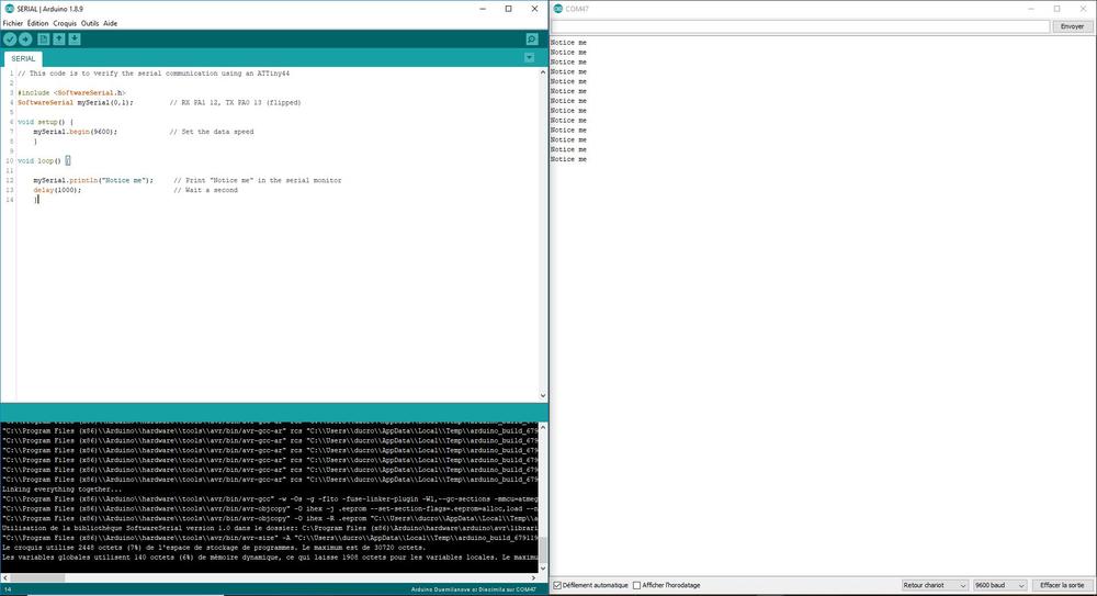
It worked so it means I can have serial connection through FTDI.
Analog input
To try the analog input, I placed a 10K potentiometer on the PC5 pin (A5) and uploaded a code to visualize the values from the ADC.
SoftwareSerial mySerial(0,1);         // RX PA1 12, TX PA0 13 (flipped)

// named constant for the pin the sensor is connected to
const int sensorPin = A5;


void setup() {
  // open a serial connection to display values
  mySerial.begin(9600);
  }

void loop() {
  // read the value on AnalogIn pin 0 and store it in a variable
  int sensorVal = analogRead(sensorPin);

  // send the 10-bit sensor value out the serial port
  mySerial.print("sensor Value: ");
  mySerial.println(sensorVal);

  delay(100);
}
It worked so it means I got values from the ADC.
I2C Communication
I used once again the accelerometer plugged in my I2C connector in my board.
#include <SoftwareSerial.h>
SoftwareSerial mySerial(0,1);         // RX PA1 12, TX PA0 13 (flipped)

#include <Wire.h>
#include <LSM303.h>

LSM303 compass;

char report[80];

void setup()
{
  mySerial.begin(9600);
  Wire.begin();
  compass.init();
  compass.enableDefault();
}

void loop()
{
  compass.read();

  snprintf(report, sizeof(report), "A: %6d %6d %6d    M: %6d %6d %6d",
    compass.a.x, compass.a.y, compass.a.z,
    compass.m.x, compass.m.y, compass.m.z);
  mySerial.println(report);

  delay(100);
}
It worked so it means I can use I2C communication boads/sensor with my board.
experimenting more with the accelerometer
I’ve decided to use an ADXL345 which is a three axis accelerometer to try to get the YAW angle of my boat. I used a brakout board which communicate via I2C to my boatduino.
I’ve used the following code :
#include <Wire.h>
#include <ADXL345.h>

ADXL345 accelerometer;

void setup(void)
{
  Serial.begin(9600);

  // Initialize ADXL345
  Serial.println("Initialize ADXL345");

  if (!accelerometer.begin())
  {
    Serial.println("Could not find a valid ADXL345 sensor, check wiring!");
    delay(500);
  }

  accelerometer.setRange(ADXL345_RANGE_16G);
}

void loop(void)
{
  // Read normalized values
  Vector norm = accelerometer.readNormalize();

  // Low Pass Filter to smooth out data. 0.1 - 0.9
  Vector filtered = accelerometer.lowPassFilter(norm, 0.5);


  // Calculate YAW (Low Pass Filter)
  int yaw  = (atan2(filtered.YAxis, filtered.XAxis)*180.0)/M_PI;


  // Output (filtered)
  Serial.print(" Yaw = ");
  Serial.print(yaw);
  Serial.println();

  delay(100);
}
The code worked well but I found two issues with this sensor :
- If we have a sudden acceleration the values are offset
- Some of values are way off
Here’s a digram with the issues I’ve faced.
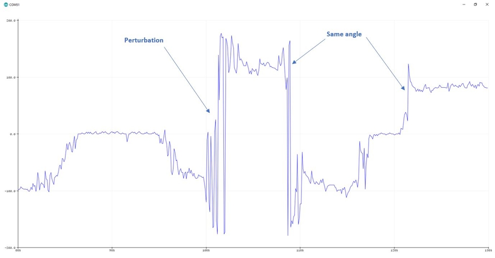
There are lots of approximation using this sensor. I decided to move to the MPU6050 which is a three axis accelerometer with a gyroscope as well.
Overall there’s a lot of learning in here and a lot of ideas for futur developpement. GREAT !

Ce(tte) œuvre est mise à disposition selon les termes de la Licence Creative Commons Attribution - Pas d’Utilisation Commerciale - Partage dans les Mêmes Conditions 4.0 International.