10. Molding and casting
Group assignment
Review the safety data sheets for each of your molding and casting materials, then make and compare test casts with each of them
Individual assignment
Design a 3D mold around the stock and tooling that you’ll be using, mill it, and use it to cast parts
| Documentation | |
|---|---|
| 1. Candle_holder.stl | 2. Candle_wax_mould.stl |
| 3. Boat_moulds.stl | 4. CandleMoldFusionFile |
| 5. BoatMoldFusionFile |
This week, I’m going to use the CNC Milling machine to make a 3D shape using wax. I will then use this shape to make a silicon mold and use this mold to cast parts.
Characterizing and testing the cast materials
Reading the safety data sheets
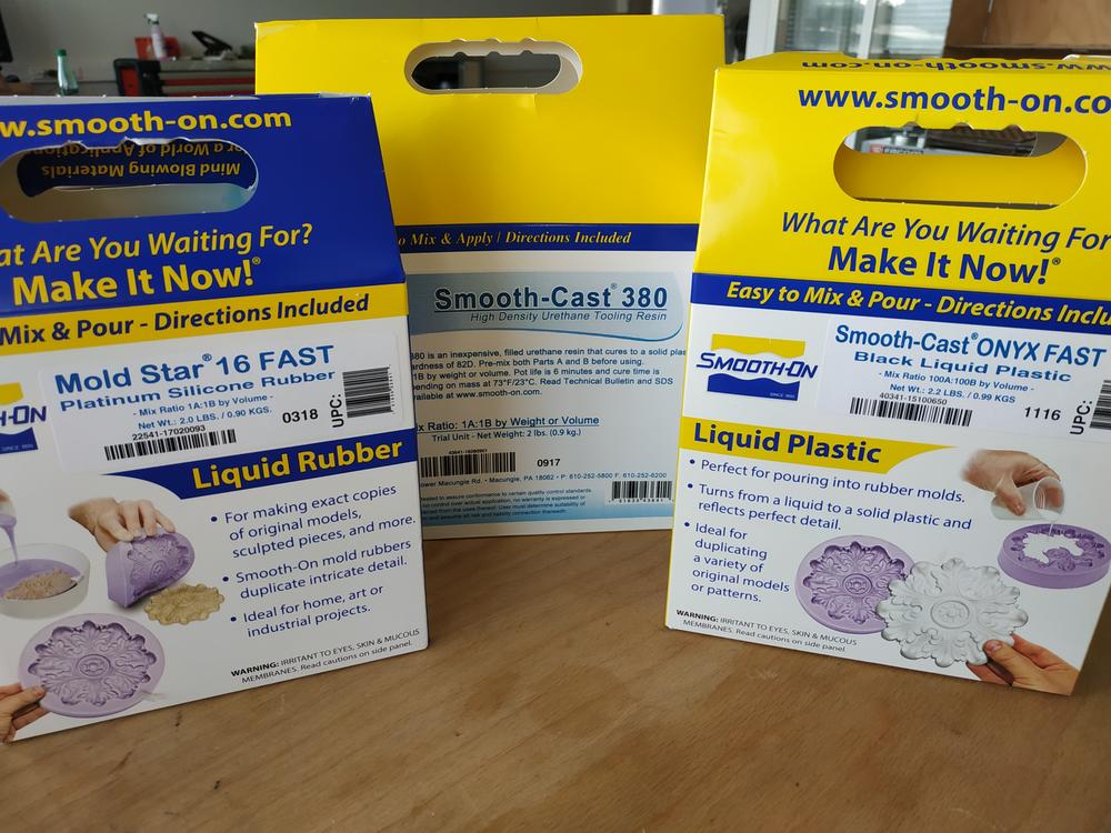
Before going through the whole process, I’ve spent time to identify the material I’ll be using.
To mould, I used the Mold Star 16 FAST from smooth-on and I’ve been though its Safety Datasheet. It’s a silicon based material and I went through the specifications of the material :
- This material has a stirring time of 6 minutes
- This material has a curring time of 30 minutes
- The mixing ratio between part A and B is 1 for 1
To cast, I used the Smooth-cast 380 from smooth-on and I’ve been though its Safety Datasheet. It’s a Urethane based material and I went through the specifications of the material :
- This material has a stirring time of 6 minutes
- This material has a curring time of 60 minutes
- The mixing ratio between part A and B is 1 for 1
NOTE : THe stirring time is how long I can stir the two components and pour it in my mould before it starts curring. The curring time is how long I need to wait before removing the part form the mold.
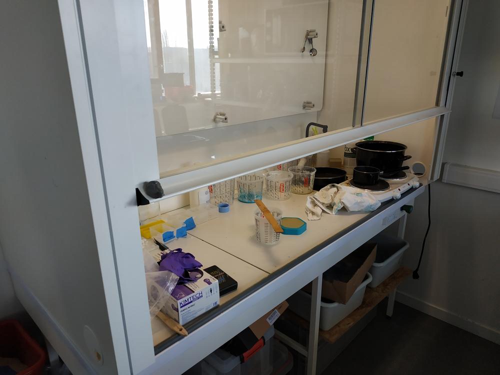
SAFETY : From the safety datatsheets I understood that the process isn’t so clean and safe so I need to use protection. In our lab we have a vent, so we won’t interact with the bad fumes, I also have to wear gloves and safety glasses. Overall, I have to be careful and keep the liquid where it’s supposed to be.
 |
 |
Testing the cast materials
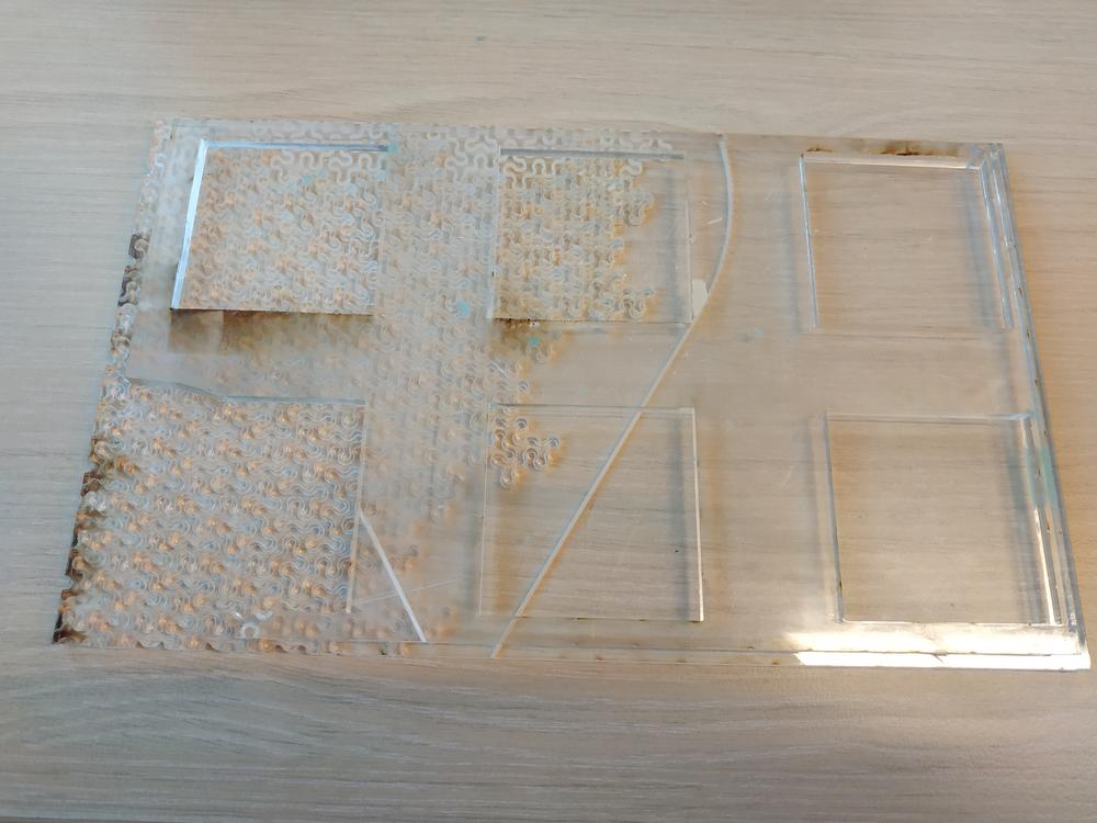
To test the materials I made a simple mold using acrylic and the lasercutter. One of the waste material had nice shapes engraved to it so I used it to see if I would be able to cast it.
The process I used to cast is the following :
- Get everything I need in the vent : A scale, Part A, Part B, something to stir, a contenair, my mould
- Switch on the vent, put on the safety glasses and gloves
- Put the container on the scale and intialize it
- Open the part A and stir it firmely
- Pour the quantity you need of part A in the contenair then close it
- Open the part B and stir it firmely
- Pour the quantity you need of part B in the contenair then close it
- Mix the two parts and then pour it in the mold
NOTE : It’s better to pour the solution from a good hight and with a tiny stream to avoid forming bubbles.
I first did it with the uretane and then the silicon.
 |
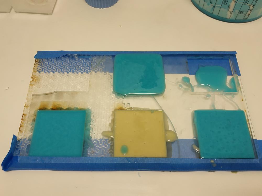 |
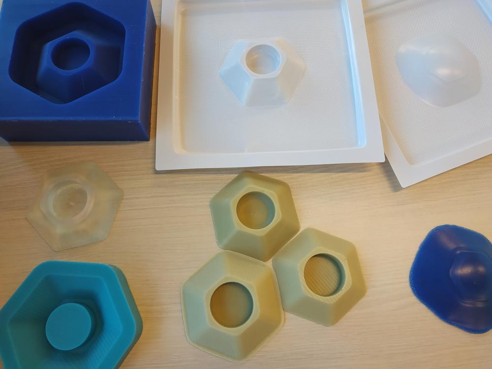
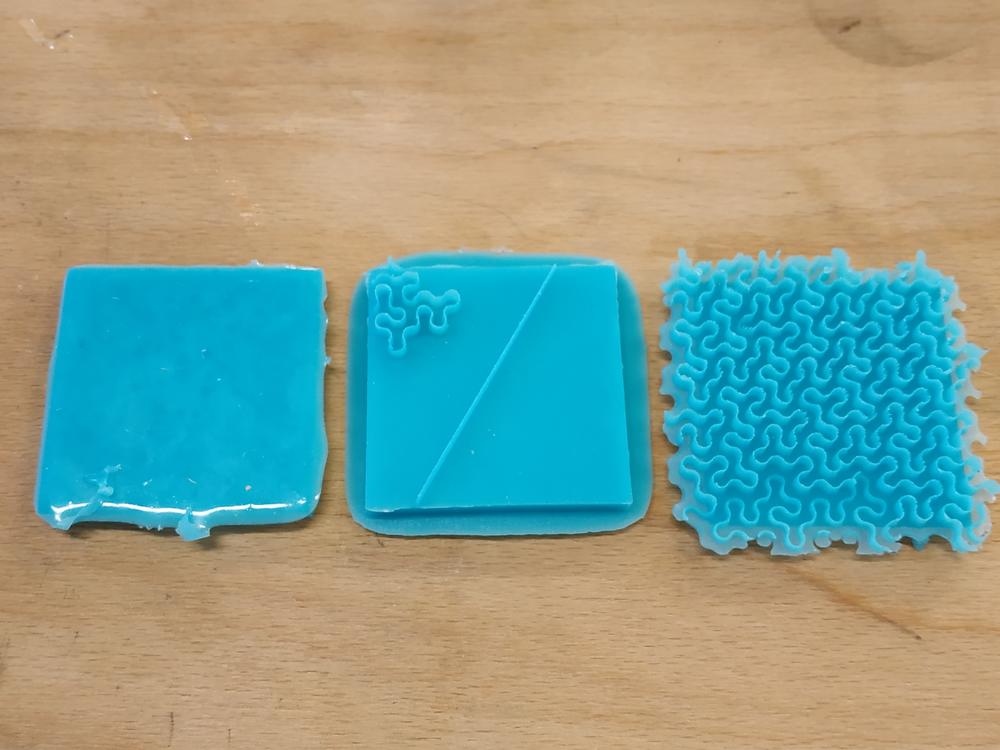
After waiting for all the parts to cure, I took them off the mold.
 |
 |
NOTE : The silicon was very easy to remove and it kept shape left by the mold which is really cool. The uretane being much harder, I used a spatula and damaged a bit the part. It also had some bublles in it.
Overall these tests were succesful, so I went for my own experimentations.
Making my own Mould/Cast
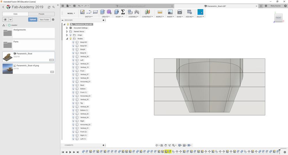
The part design
To experiment this process I’ve decided to go for a candle holder. I’ll be using the shopbot to machine some wax in order to create a form that I’ll use to pour silicon in it to make my mold.
 |
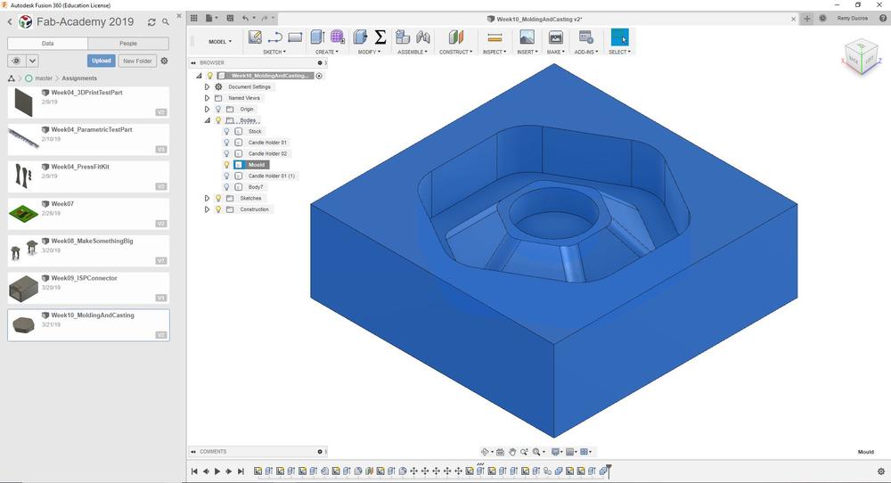 |
I followed some design rules for this design :
- There’s no inner sharpe edges a end-mill wont be able to cut
- There’s room everywhere for a 1/4” end mill to go
- I left a 5mm gap all other the part for the silicon to go
I saved the form as STL and went to V-Carve to start the job.
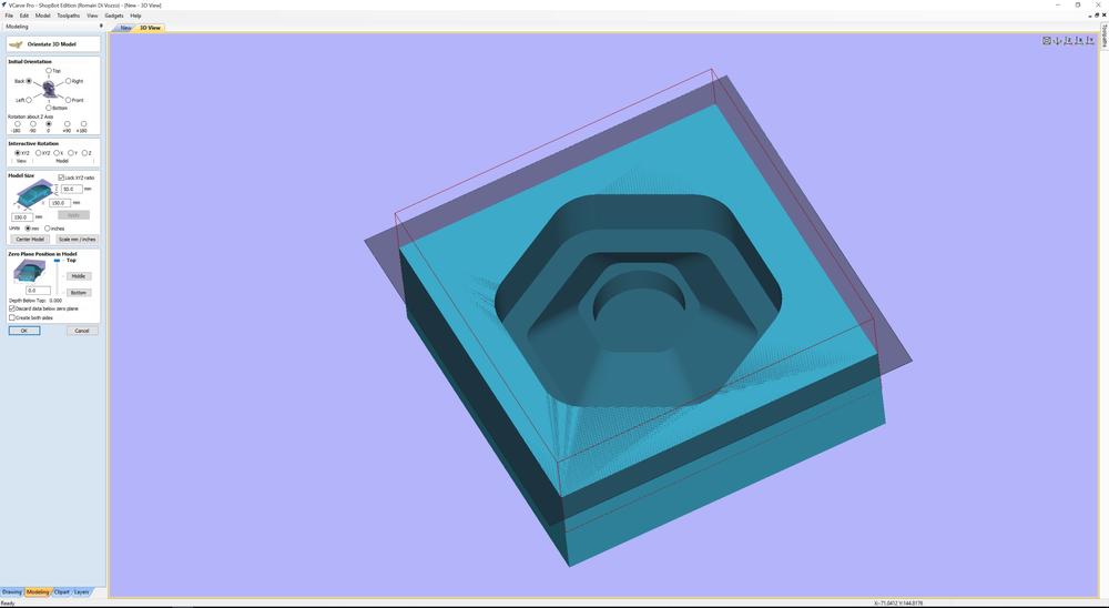
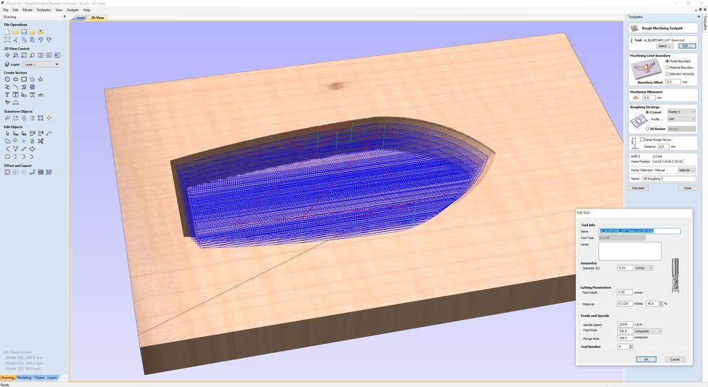
Machining the wax
First I started a new job in V-carve and gave the details of my stock. Then I imported my STL file. I first had to make it fit in the stock with the proper orientation.
 |
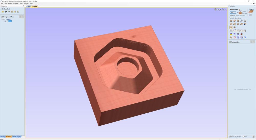 |
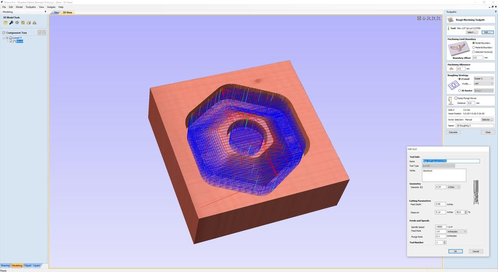
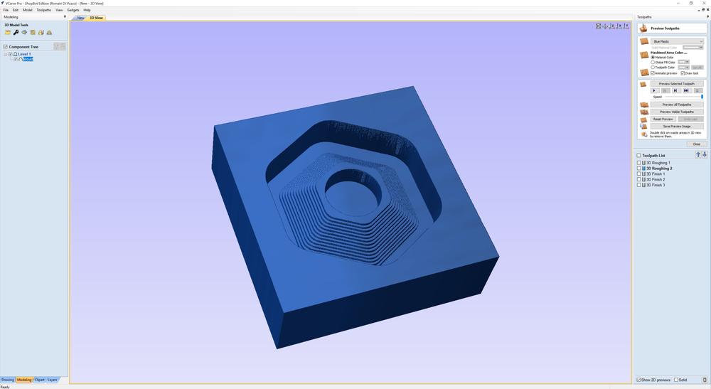
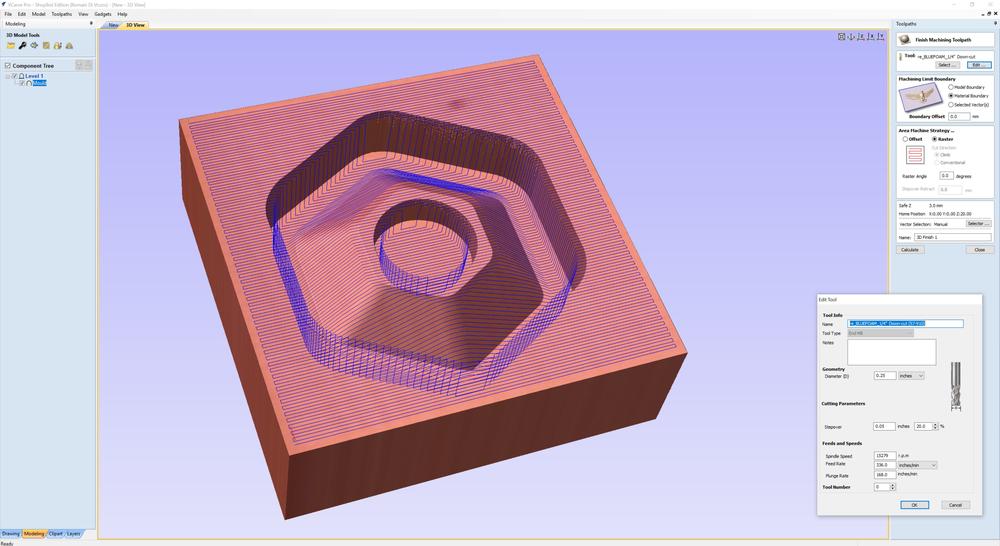
Then I could see my part was properly imported I went to toolpath and created a 3D Roughing Toolpath. I had to create a new tool for this job, then I simulated it.
 |
 |
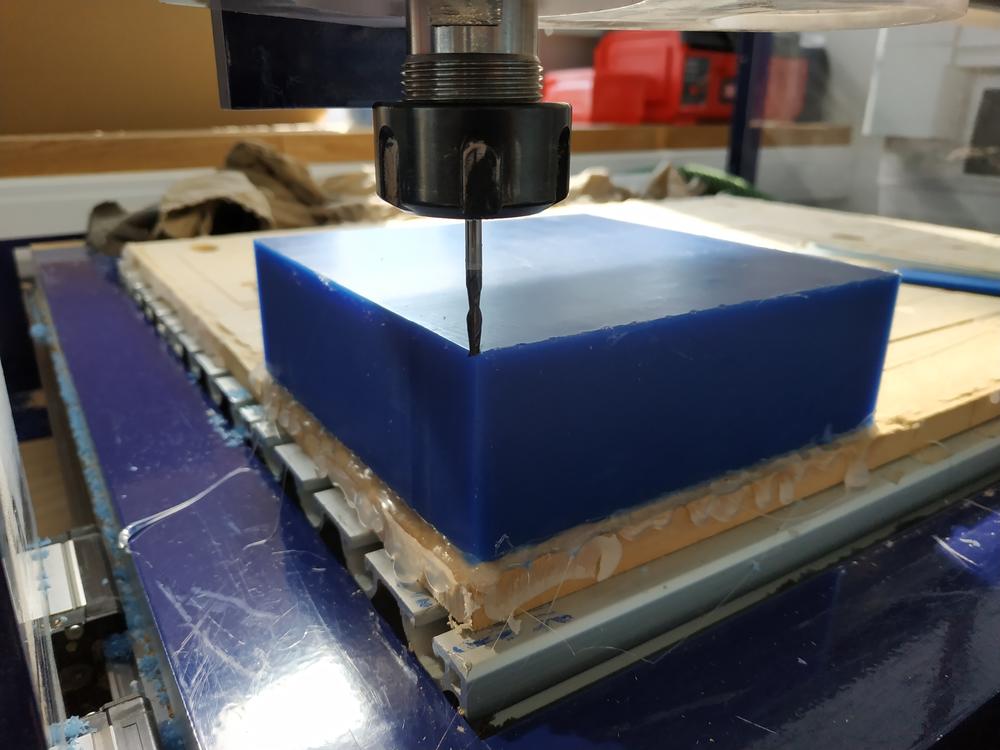
Once it was ok, I prepared the machine and started the job.
 |
 |
NOTE : I didn’t left the bit out enough, so I had to stop the job, removed the wax, flipt it over and started other again.
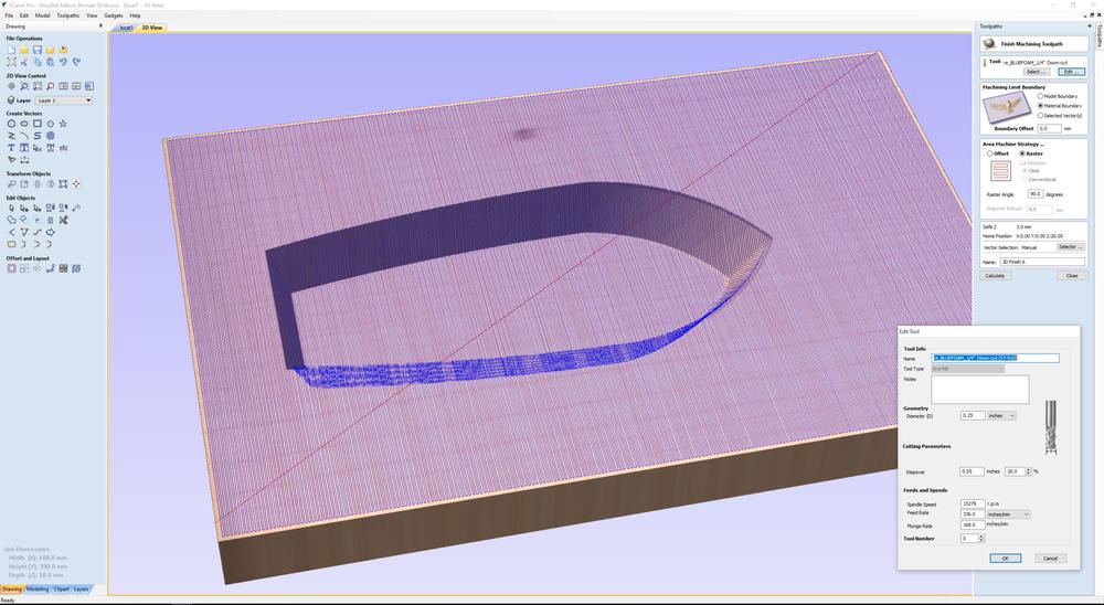
Once this was done I went for a 3D Finishing Toolpath.
 |
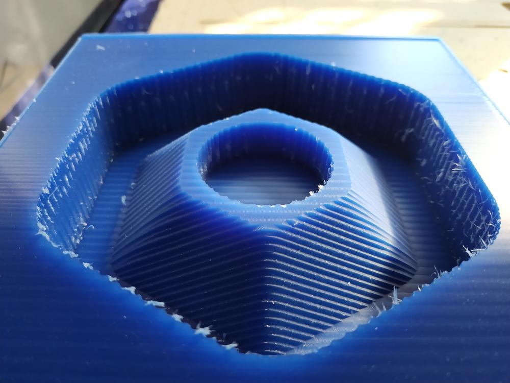 |
NOTE : I didn’t change the stepover and it was a mistake at this point, the result was rough.
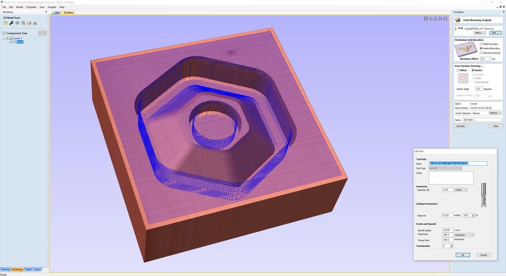
I then did another 3D finishing toolpath, perpendicular to the previous one but with a stepover of 5%.
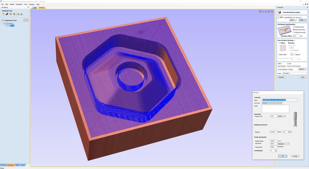 |
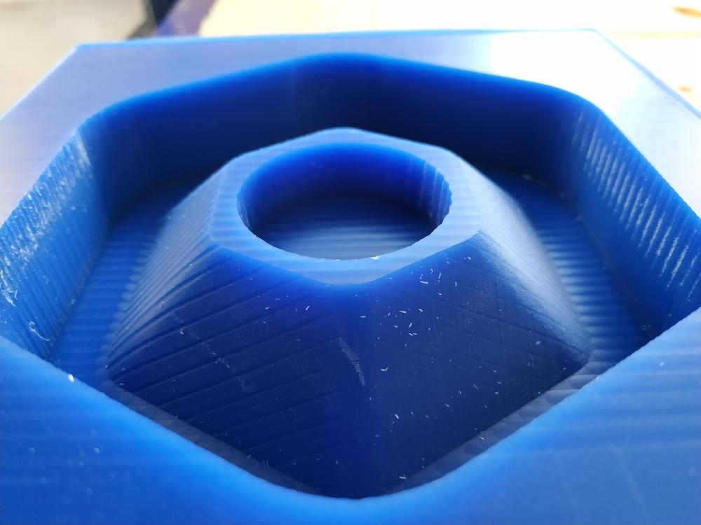 |
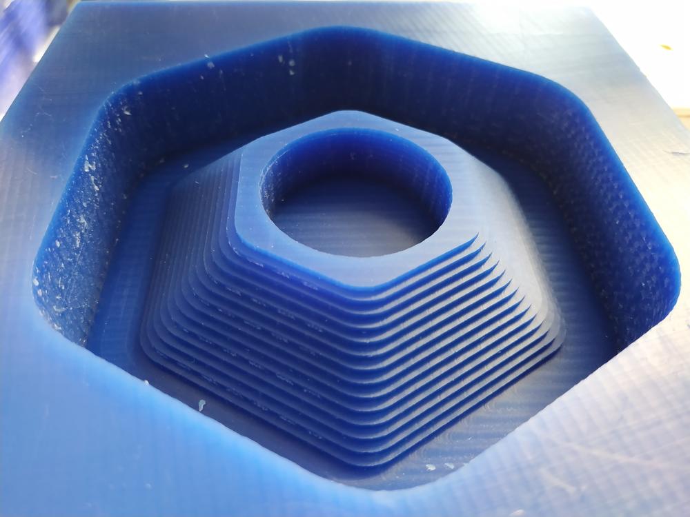
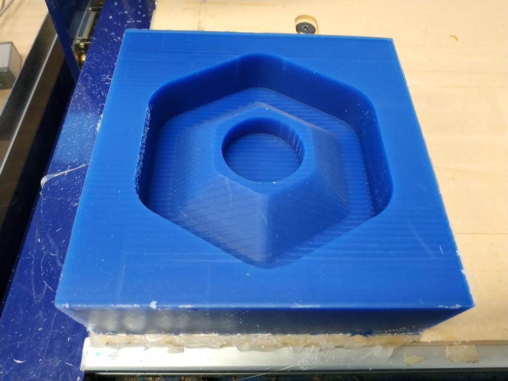
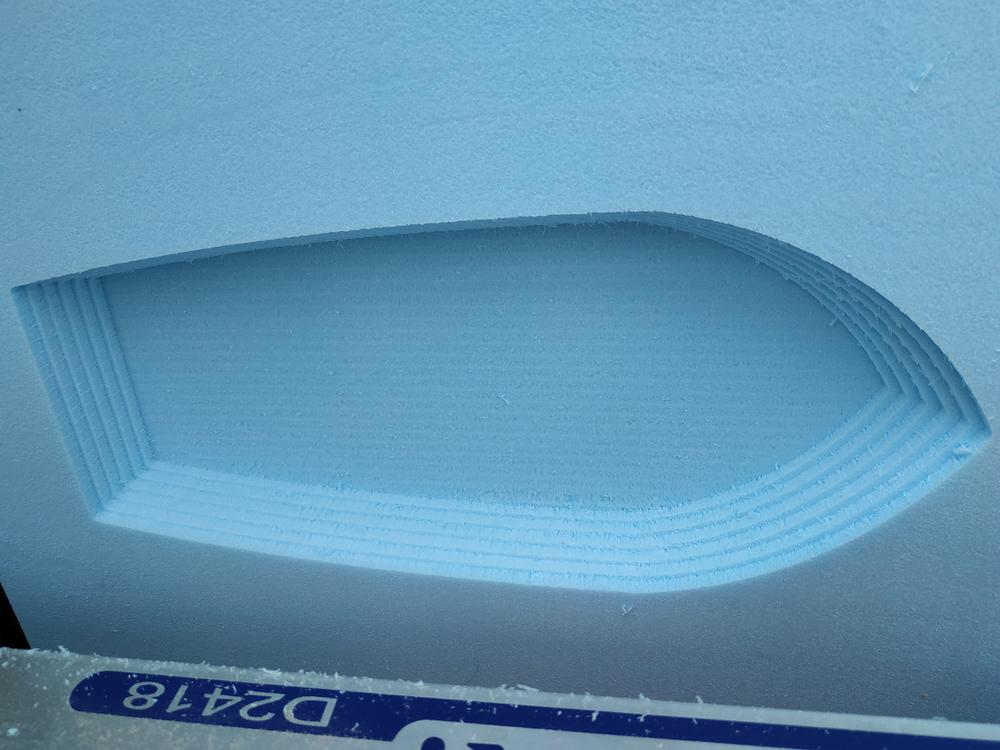
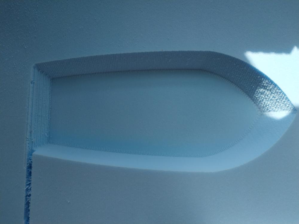
It took two hours but the result was much better. I made a last 3D finishing toolpath, the same orientation than the first one but with a stepover of 10%.
 |
 |
This time I have a final part even if the mistake I made from the first 3D finishing toolpath left some marks.
NOTE : I think that for a finish path a stepover of 10% is enough to have a clean result.
Making the mould
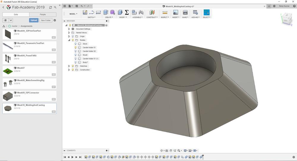
To make the mould, I took the wax off the machine and I checked in fusion 360 the volume of my solid. To check this you just have to right click on the body and go to properties. If you set the material right (I didn’t here) you have lots of interesting informations. Here the most intersting setting is the volume (it is always the same regardless the material). My part is about 200 000 milimiter cube, which is about 200ml.
 |
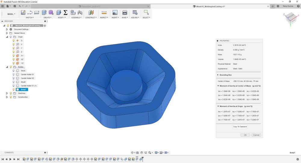 |
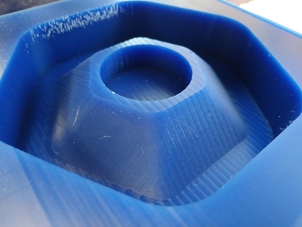
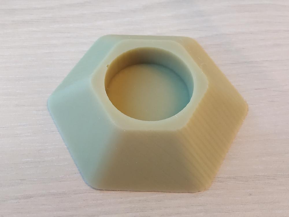
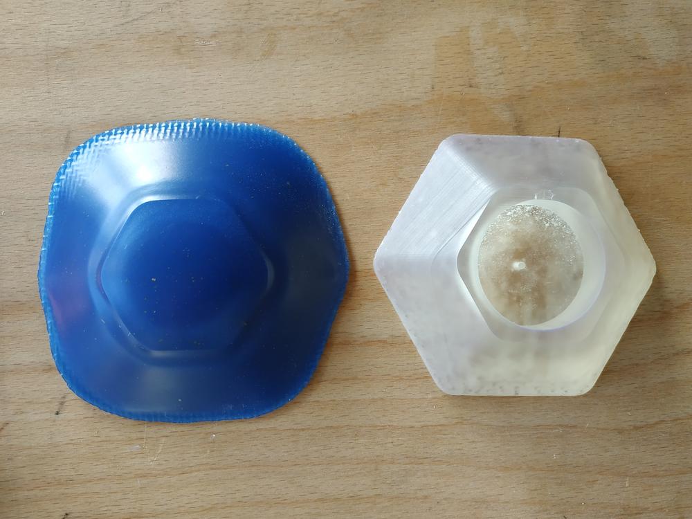
Knowing the volume and following the process discribed before, I mixed 100ml of each part and pourred it in my wax mould. After waiting for the mix to cure, I removed the silicon easily.
 |
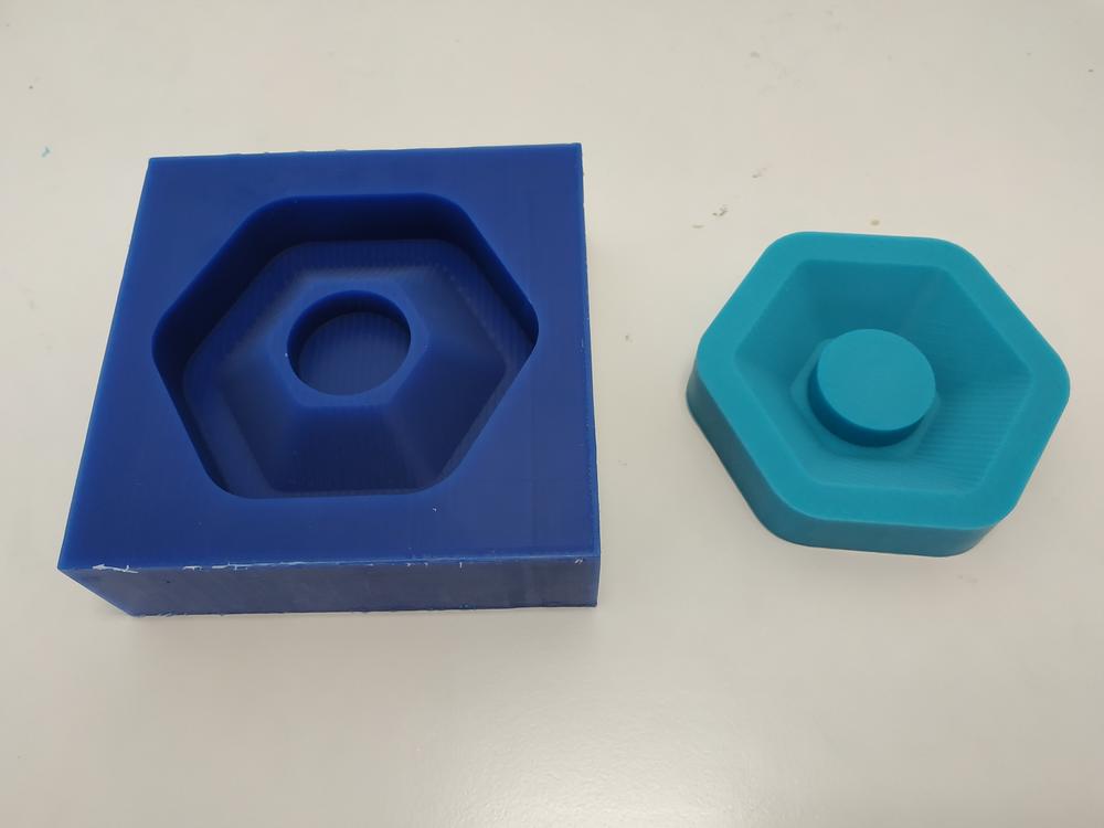 |
Now I have a mold and I can cast parts in it !
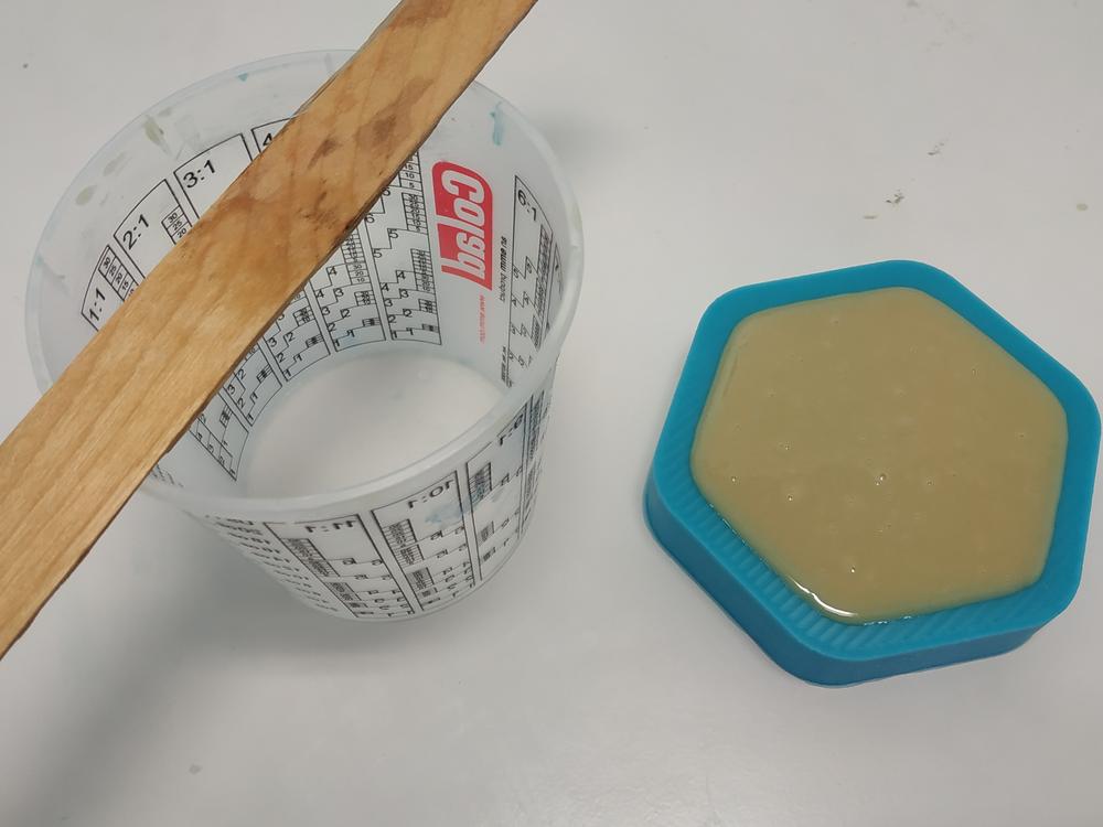
Casting parts
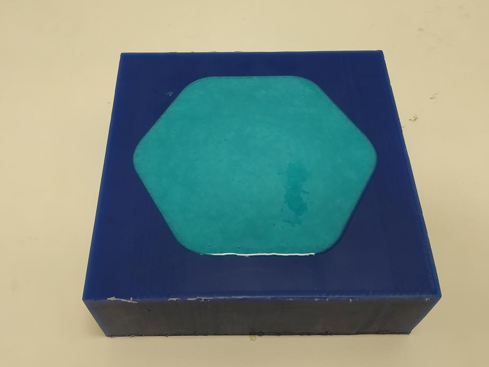
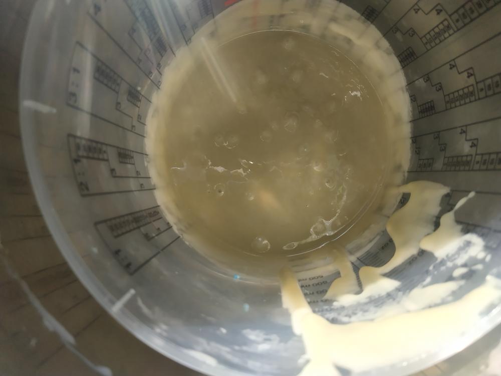
Confident with all my previous tests, I checked the volum of the part in Fusion (here around 100mL), I mixed the parts and pourred it in the silicon mold.
 |
 |
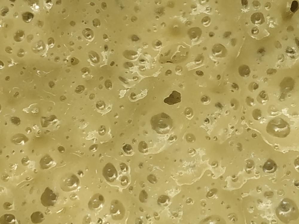
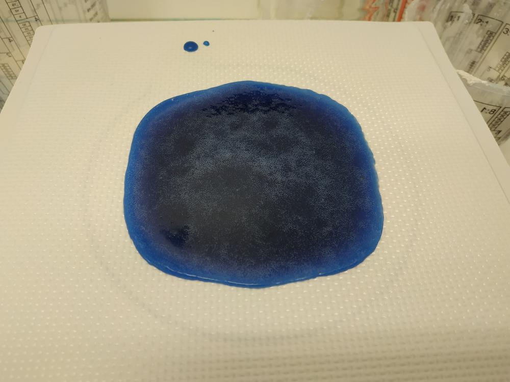
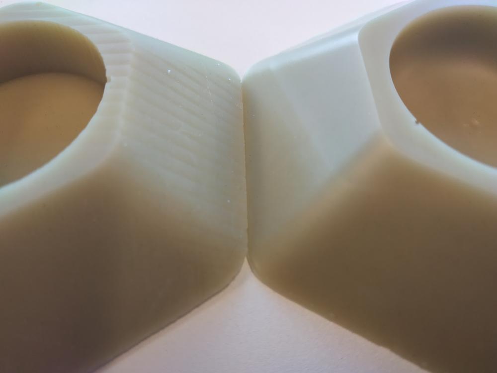
I noticed that the mix gained a bit of volume (maybe because of air bubble created by heat) and the parts had some bubbles in it.
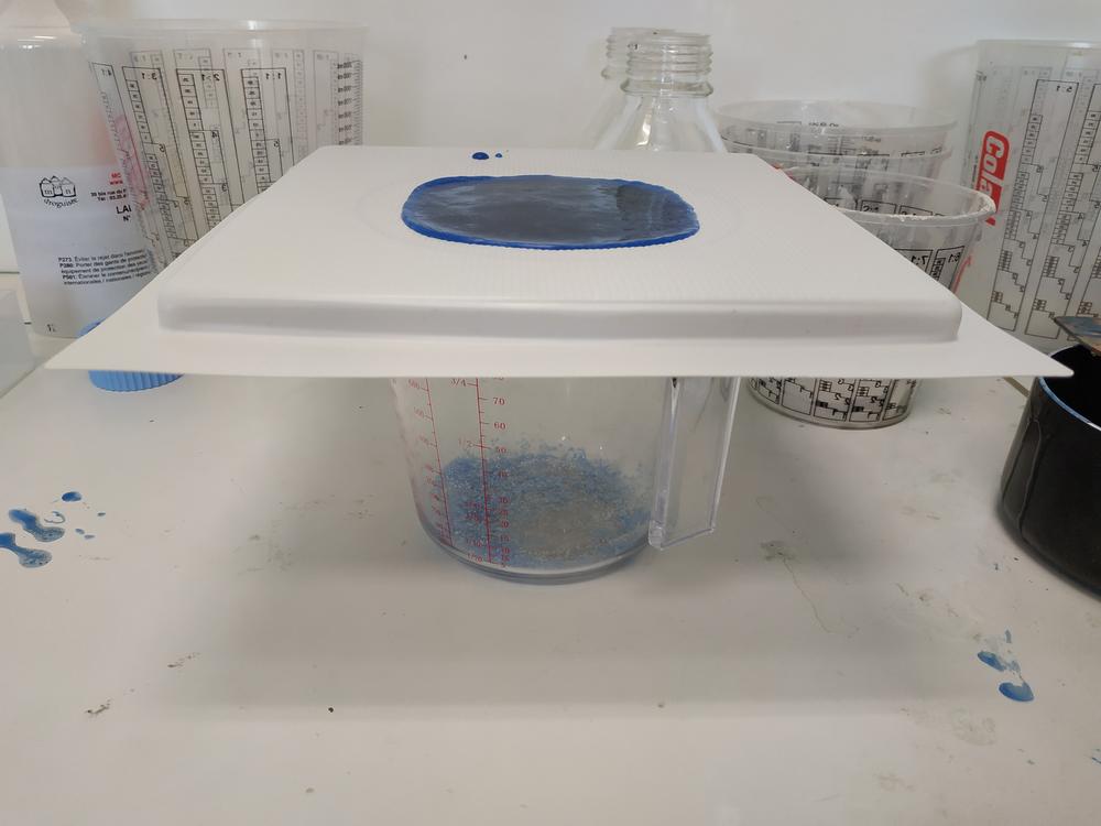
I tried to improve the quality of my part by putting my mix in a vacuum chamber before pooring it in the mold.
I made another mix and placed it in the vacuum chamber. When I started the vacuum, I can see the mix expand and all the air going away from it.
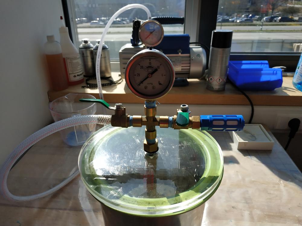 |
 |
 |
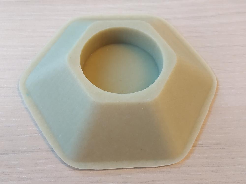
After releasing the air, I pourred the mix in the mould.
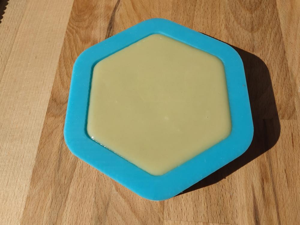 |
 |
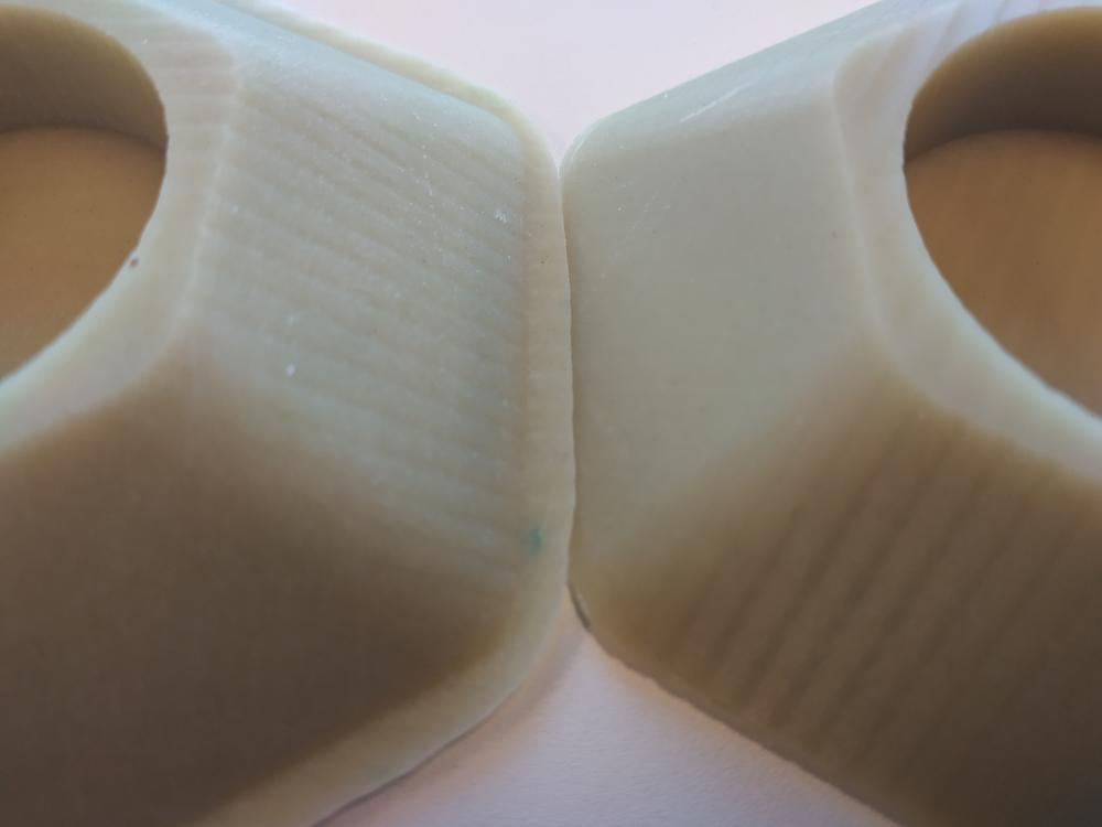
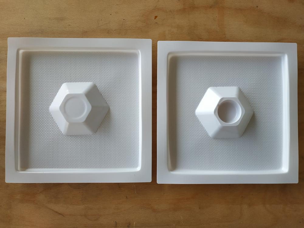
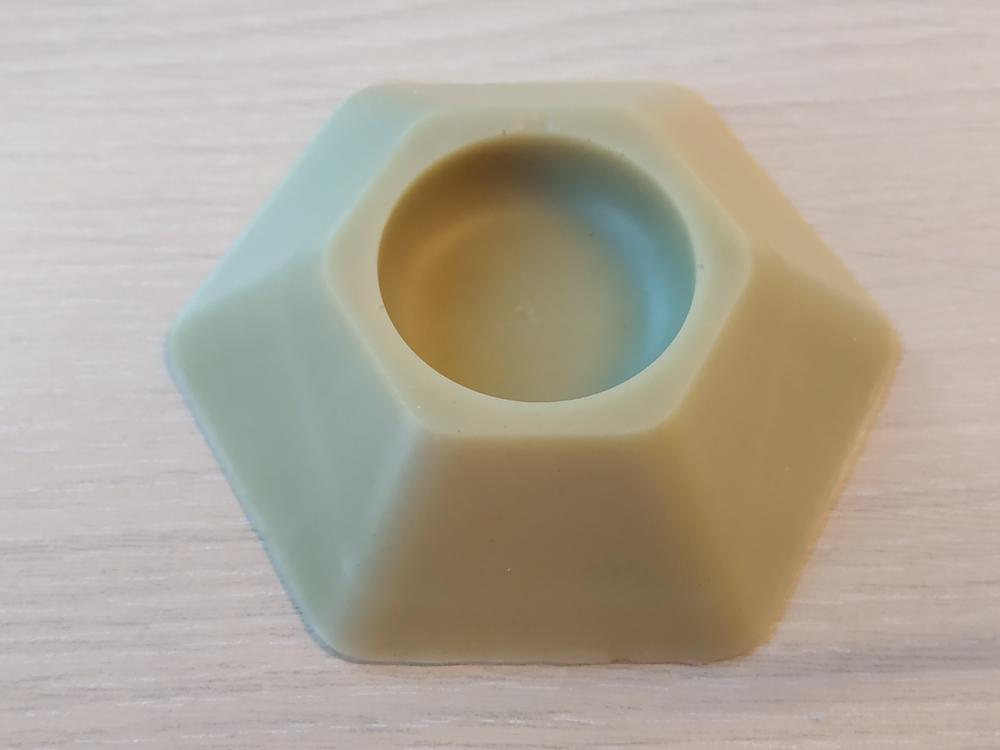
I could see a much better finishing with this part. The vacuum really helps improving the quality. Here is a comparaison between the same part with and without placing the mix in the vacum chamber.
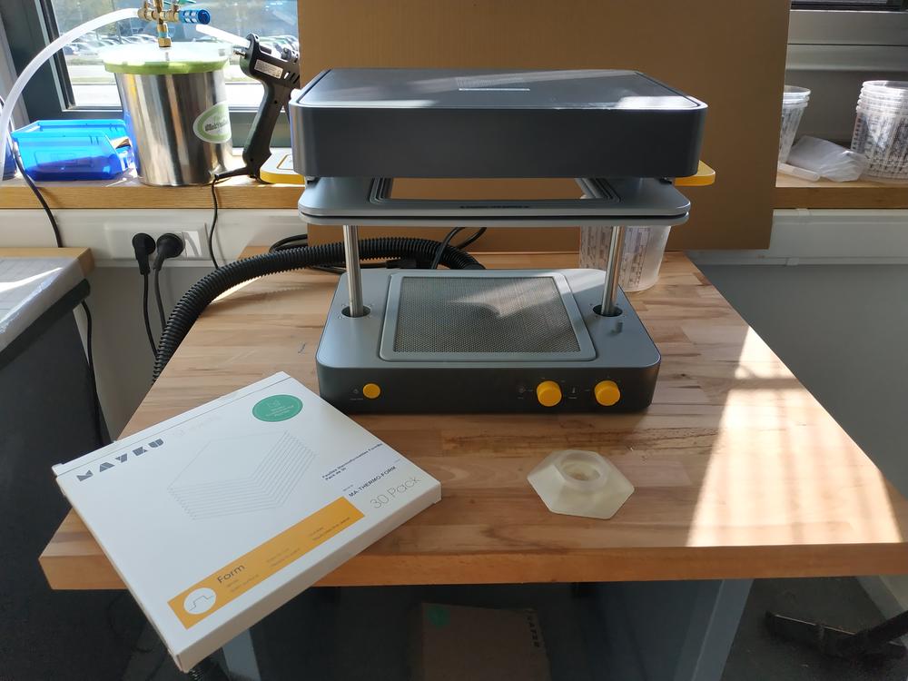
Making a mold using the vacuum forming machine
We have acces to a desktop vacuum forming machine and I really wanted to try it to make a mould of my candle holder and try to cast things out of it.
Making the part
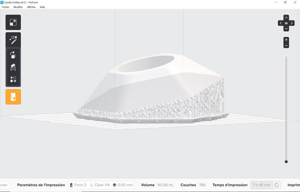
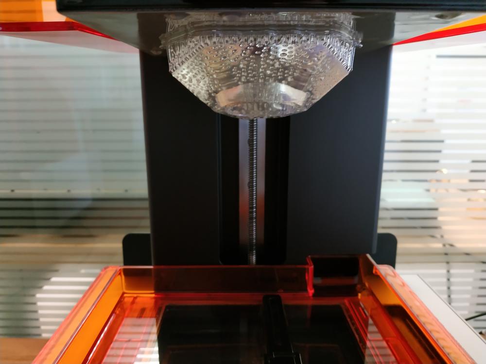
For this test, I 3D printed the candle holder using the SLA printer.
 |
 |
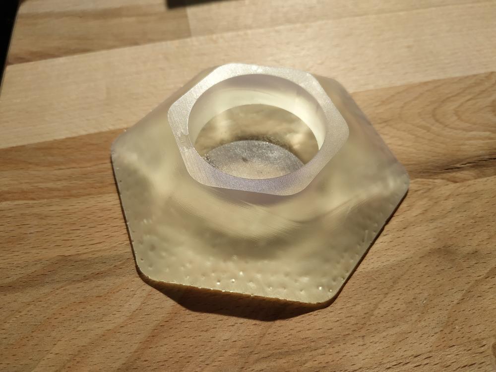 |
As we can expect with this printer the surface finishing is very good. However I saw two small defaults. A “ligne” on a edge and a missing part at the top.
Making the mould
I used this part to create my mold. Using the machine is pretty simple, I followed this online tutorial.
I used a plastic sheet from the manufacturer so the timing were easy to set.
 |
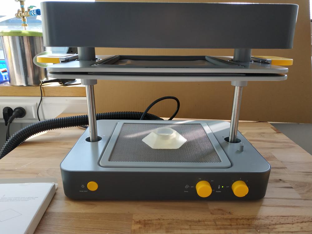 |
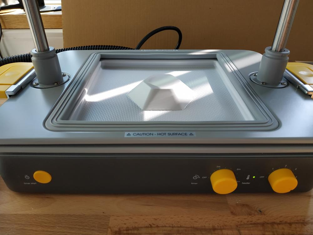 |
As we can see on the photo, the hole for the candle didn’t formed properly as the air couldn’t get suck out of it so I made a hole in my part and this time it worked.
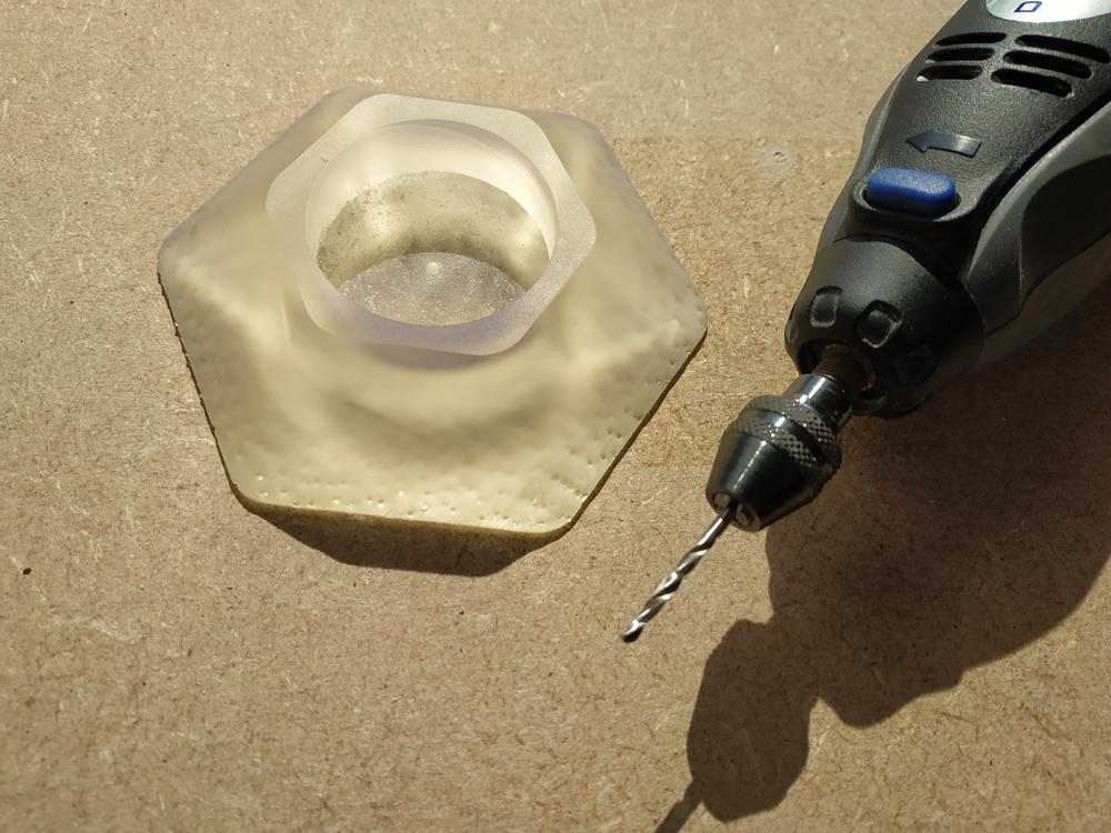 |
 |
Casting parts
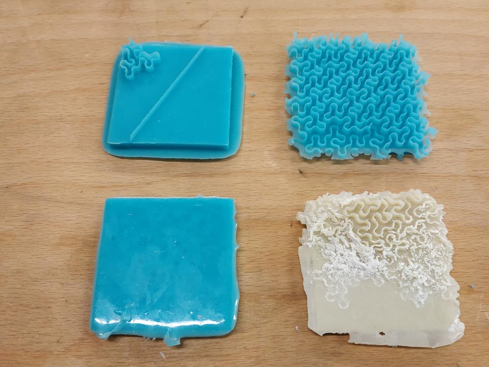
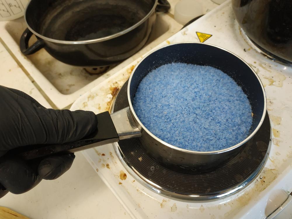
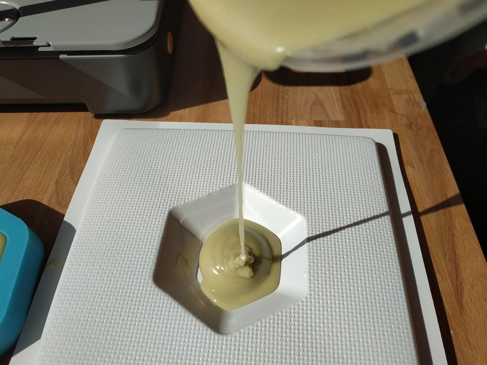
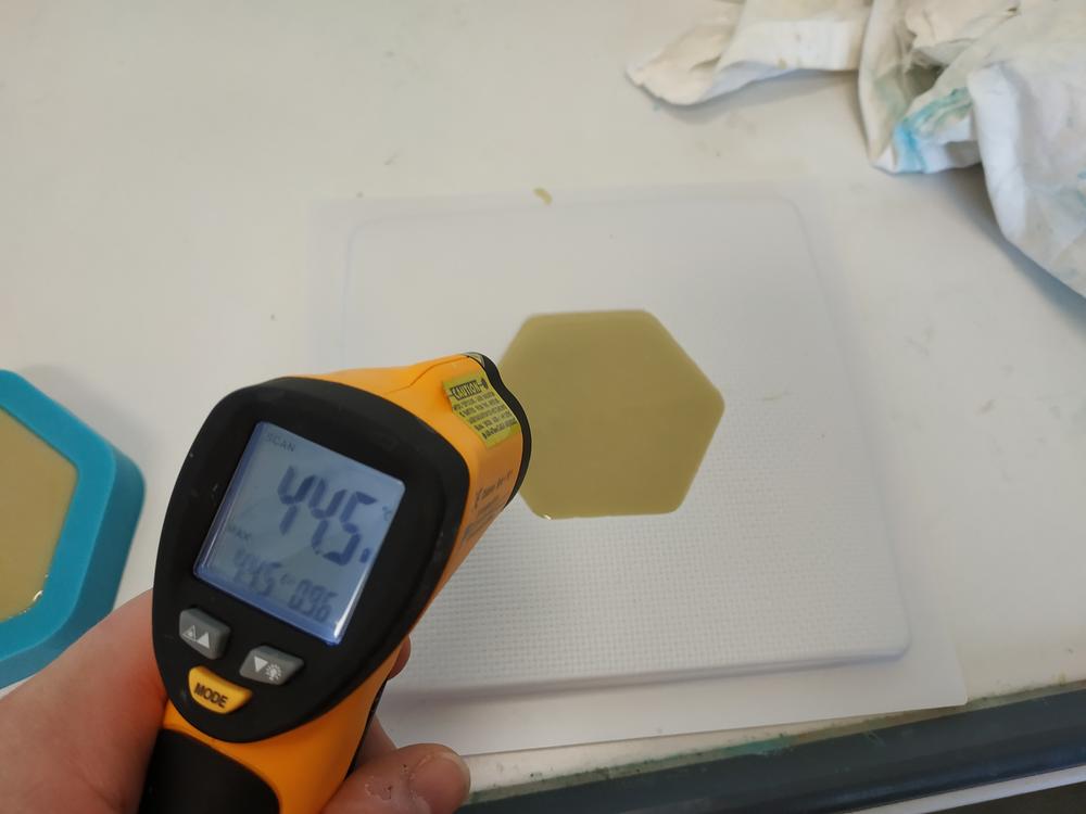
I thought it would be nice to cast out of my mold. I wanted to try casting the wax I removed from machining back to a part. I melted the wax and measure its temperature.
 |
 |
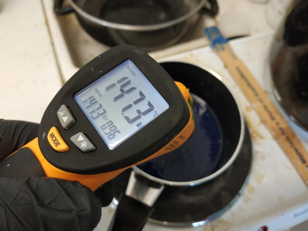 |
I’ve seen that the machine heats from 160°C to 300°C. Here the temperature of the melted wax was just below 160°C so I tried pouring it in my first mold. I felt that the plastic was getting soft, so I placed the mold on a top of a cut in case anything broke.
 |
 |
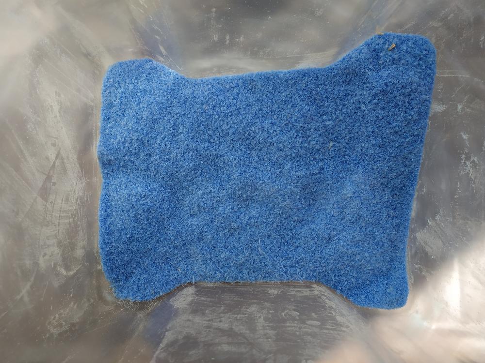
The plastic was deformed by the heat but I removed the part very easily. The form isn’t exactly the shape I expected.
During my previous tests I’ve seen that the casting material I used didn’t create much heat so I used it to cast in my second mold. I used the vacuum chamber and the process I’ve detailed before.
 |
 |
After the curring time, I removed the part but it damaged the mold. I think that if I used a release agent, I can make more parts with this mold.
 |
 |
Here I got the best result because the surface finishing of my mold was better. I think I could have reached the same result if I’ve set the proper settings making the mold using the shopbot.
Preparing the toolpath in using Fusion 360
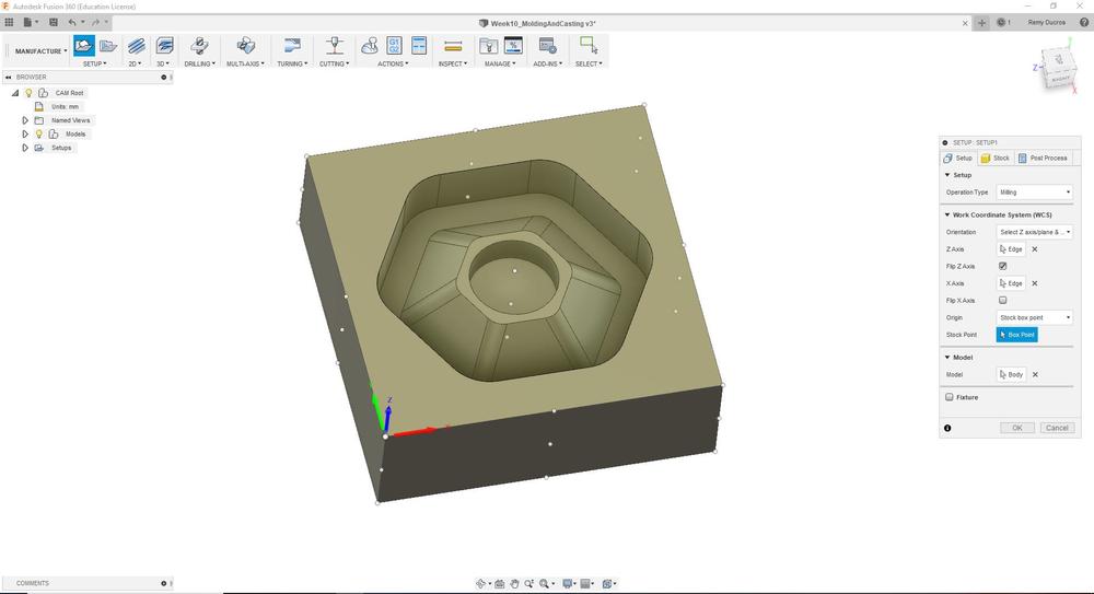
In Fusion 360, There’s also a way to simulate a toolpath and export a G-code to use directly to the machine. First thing to do is to go from Design to Manufacture and create a new Setup. The Setup is where we detail the stock volume and the origin.
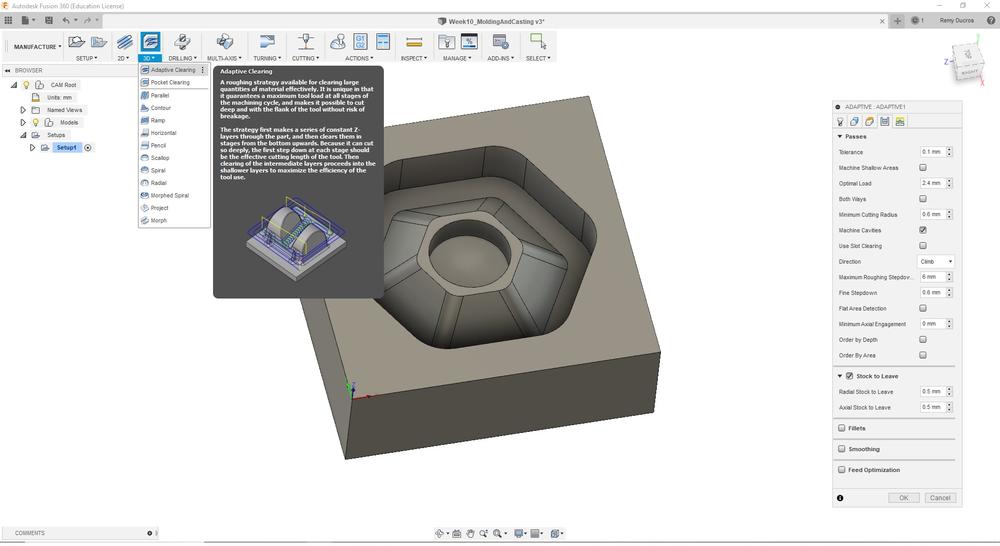
Then we have options of 2D or 3D machining we can make. Here I first did a 3D Adaptive Cleaning which is the equivalent of 3D Roughing Toolpath in V-Carve. First thing to do is to create a new tool and set all the details (like in V-carve).
 |
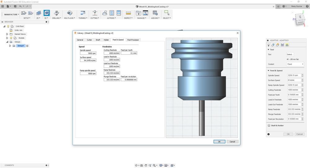 |
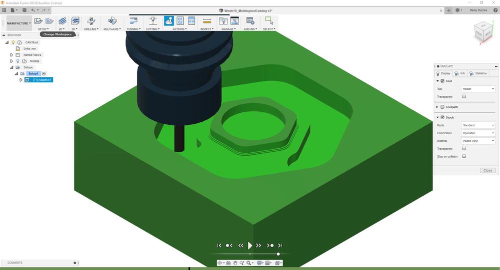
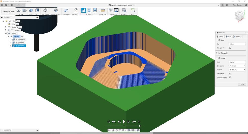
After setting up the tool, we can set important settings like the pass depth or the stepover. Once we’ve defined the correct settings, the software calculates the toolpath. We can then simulate and see if everything is going to go as plan.
 |
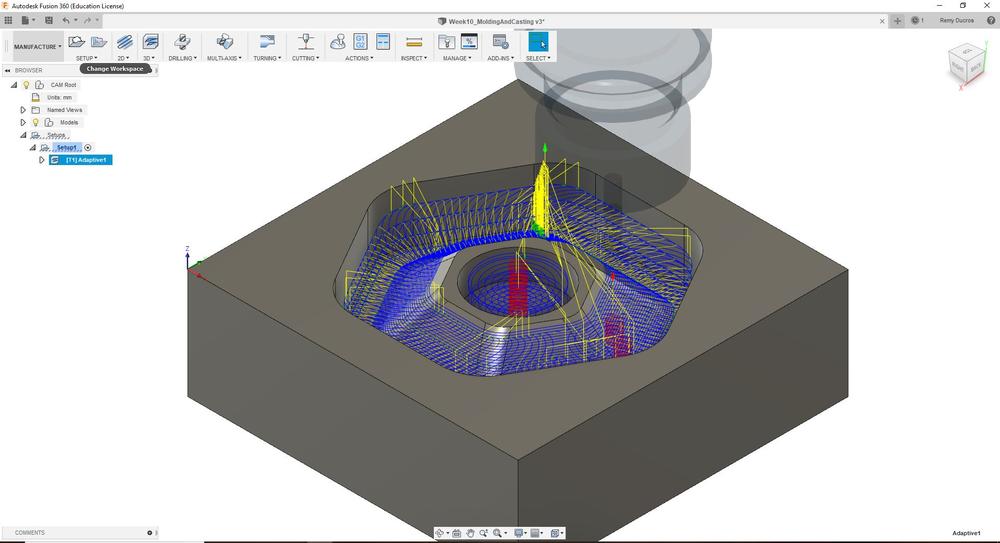 |
 |
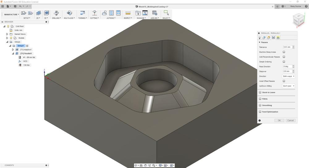
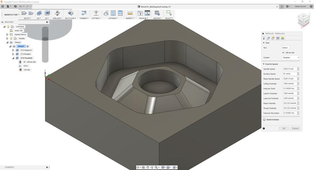
I then did a finishing 3D toolpath by doing a 3D parallel. I set here a stepover of 10%.
 |
 |
Finally I did finishing 3D toolpath by doing a 3D parallel but perpendicular to the previous one. I set here a stepover of 10%.
 |
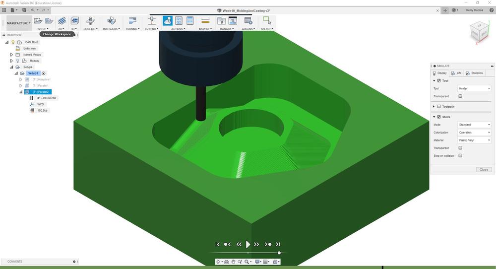 |
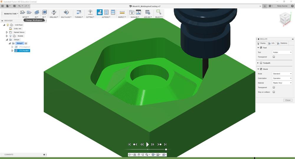
Then you can simulate the whole toolpaths at once :
Finally we can export the G-code created by the software and run it directly in the shopbot. For this we have to install a post processeur. What it will do is make the starting G-code and Ending G-code with the command lignes to run the machine properly. To find the post-processeur, we can download it from this website, download it and upload it in the software assets. Once it’s installed we just click the post-process button, select the Shopbot post-processor and export the file.
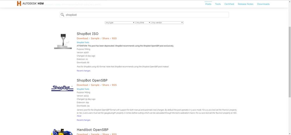 |
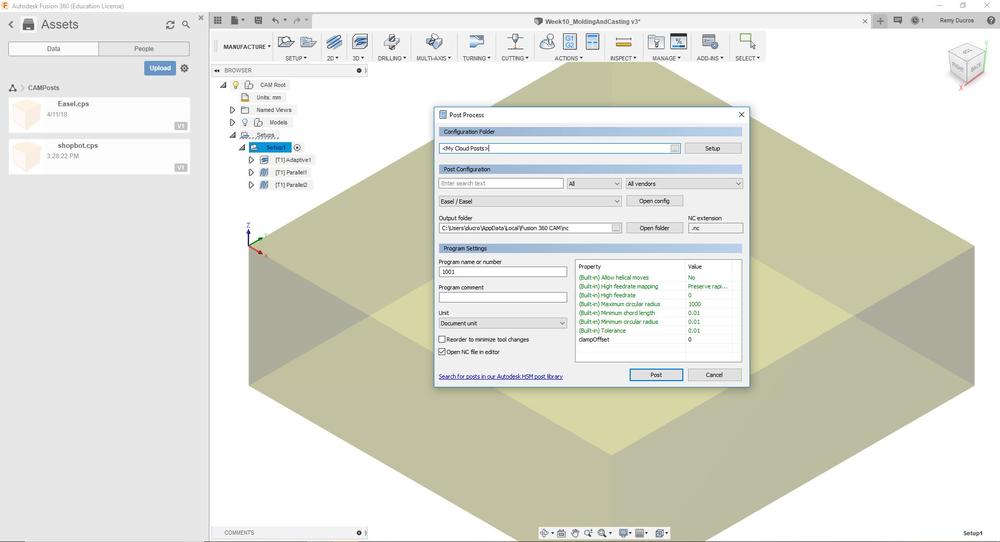 |
NOTE : Running the file, the shopbot will do all the different toolpaths, we won’t have to make three toolpaths and run them seperatly.
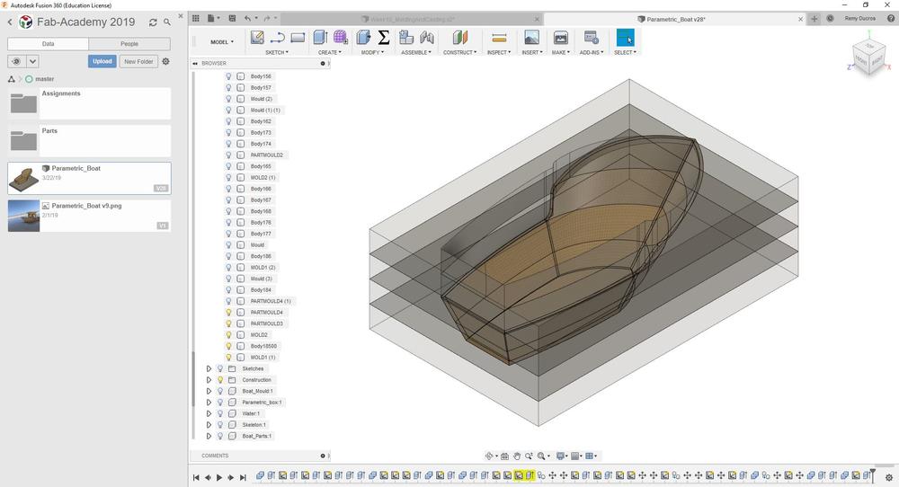
Making the mould for my boat
The design of the mould
For my boat I want to make the hull using a mold so I made on using thick foam. I first created the mold in Fusion 360. I need four stocks of 50mm thickness to make the whole mould.
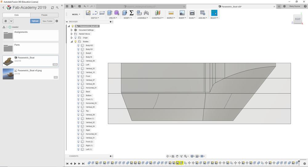 |
 |
 |
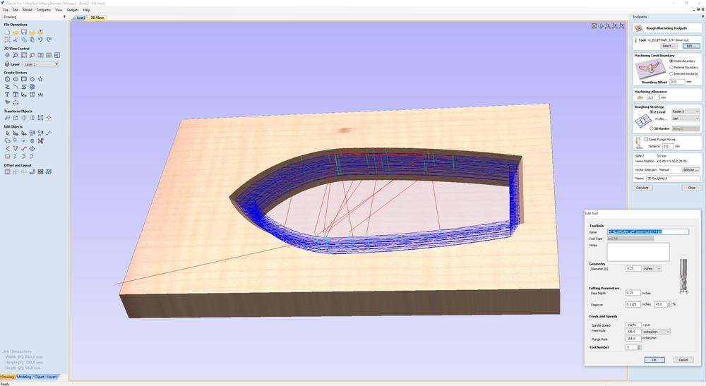
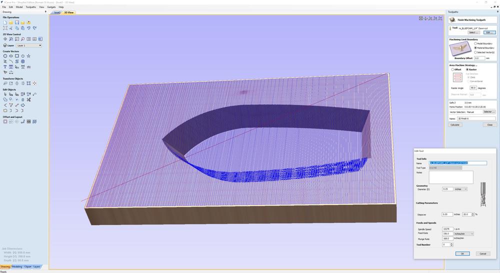
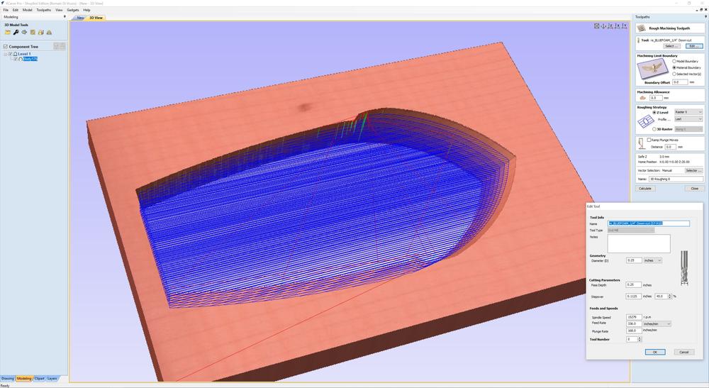
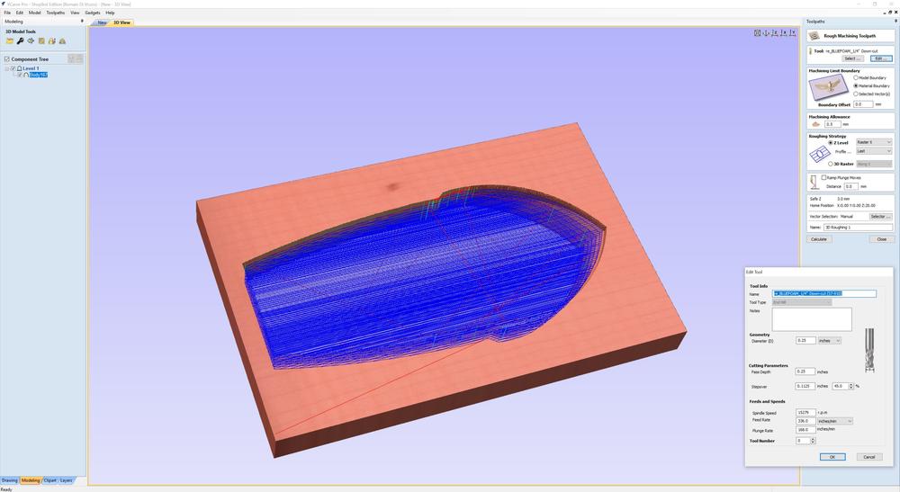
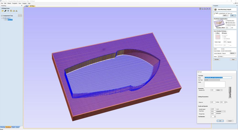
I used a 1/8” end mill with two flutes and ran a 3D Roughing Toolpath followed by a 3D Finishing Toolpath with the same tool and a stepover of 20%. I kept the stepover quite high for the finishing path because the material is so soft, It wont be such a big problem to sand it.
3D roughing toolpath for the first stock
 |
 |
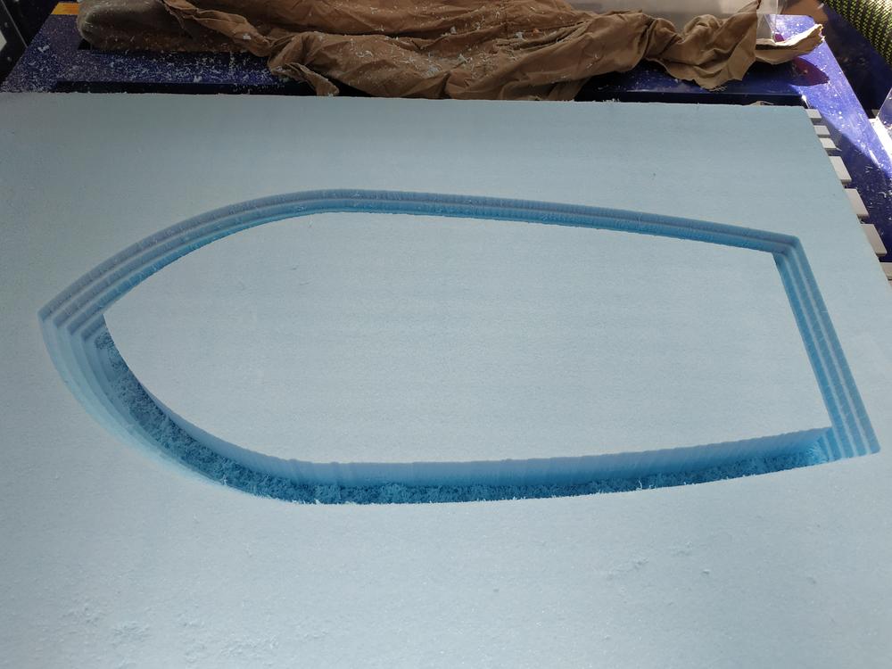
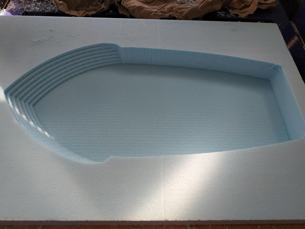
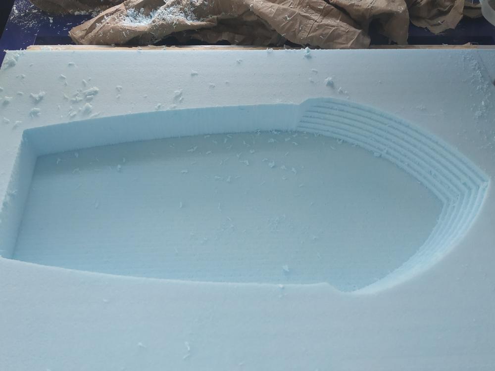
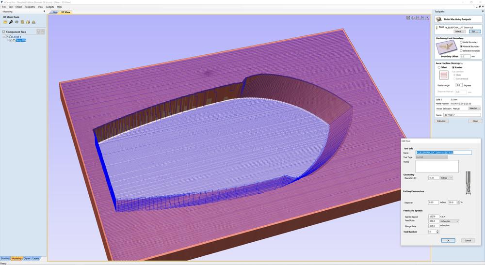
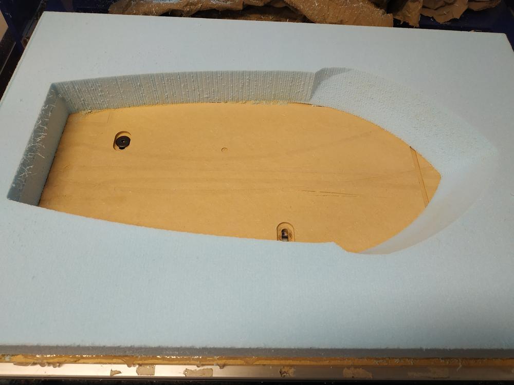
3D finishing toolpath for the first stock
 |
 |
NOTE : During the finishing path the machine shiftted on an axes. It was at the end so it’s not big problem, I can fix it later.
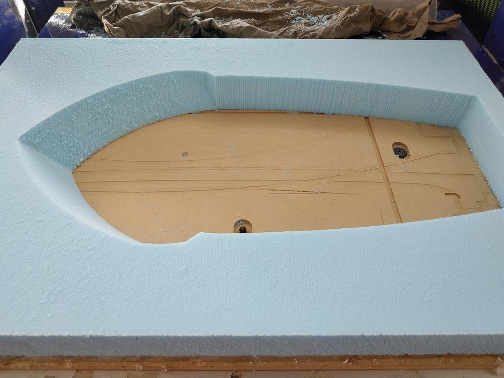
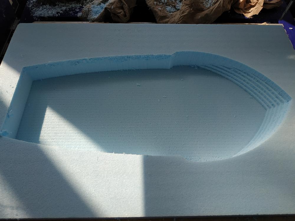
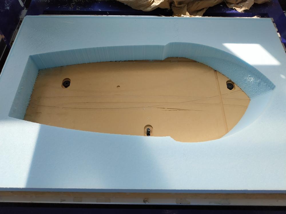
3D roughing toolpath for the second stock
 |
 |
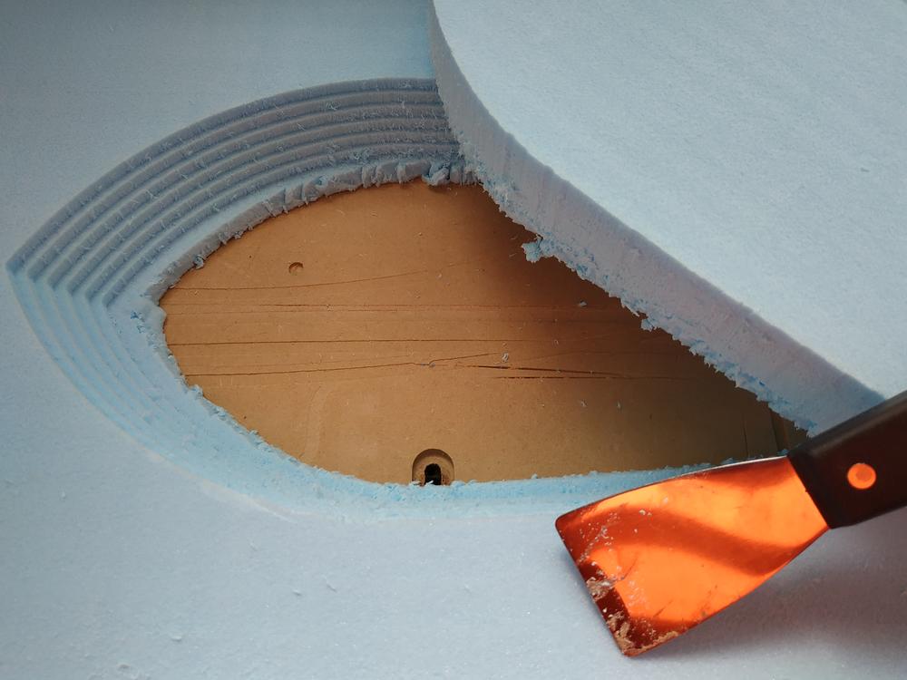
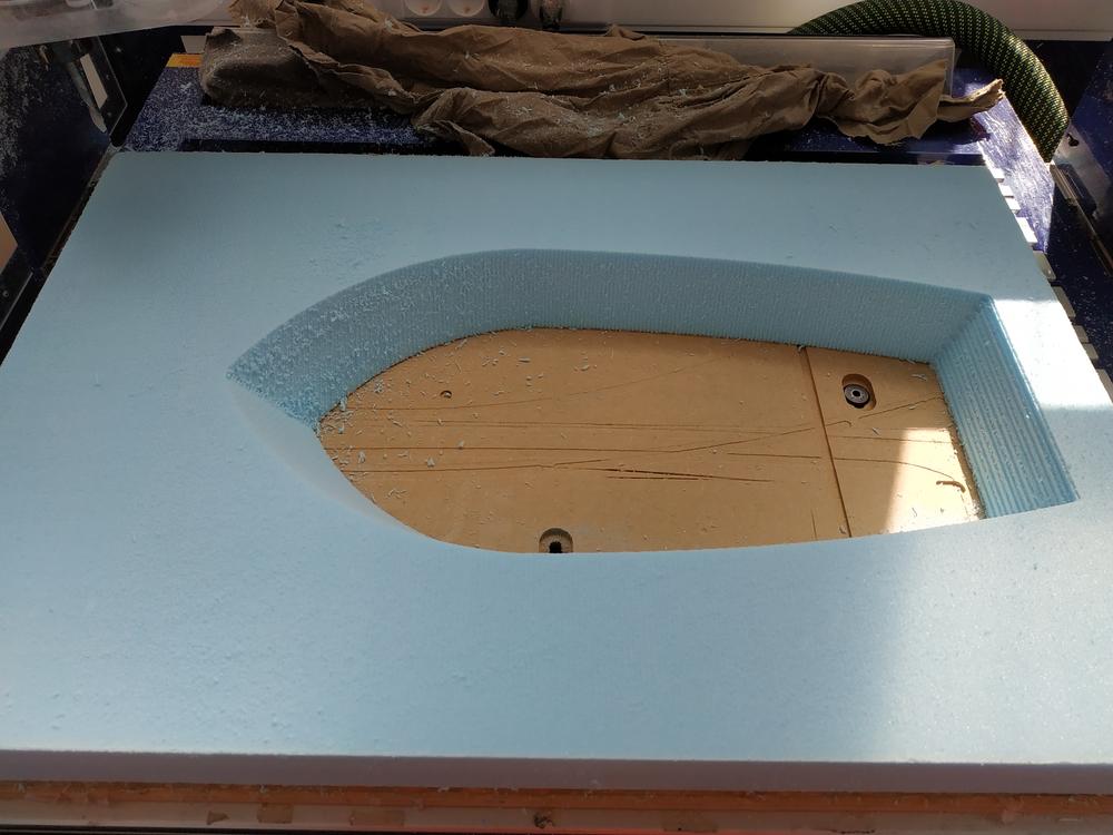
NOTE : The drill bit didn’t removed all the inside of the mold so I did it by using a spatula
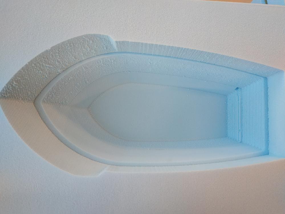
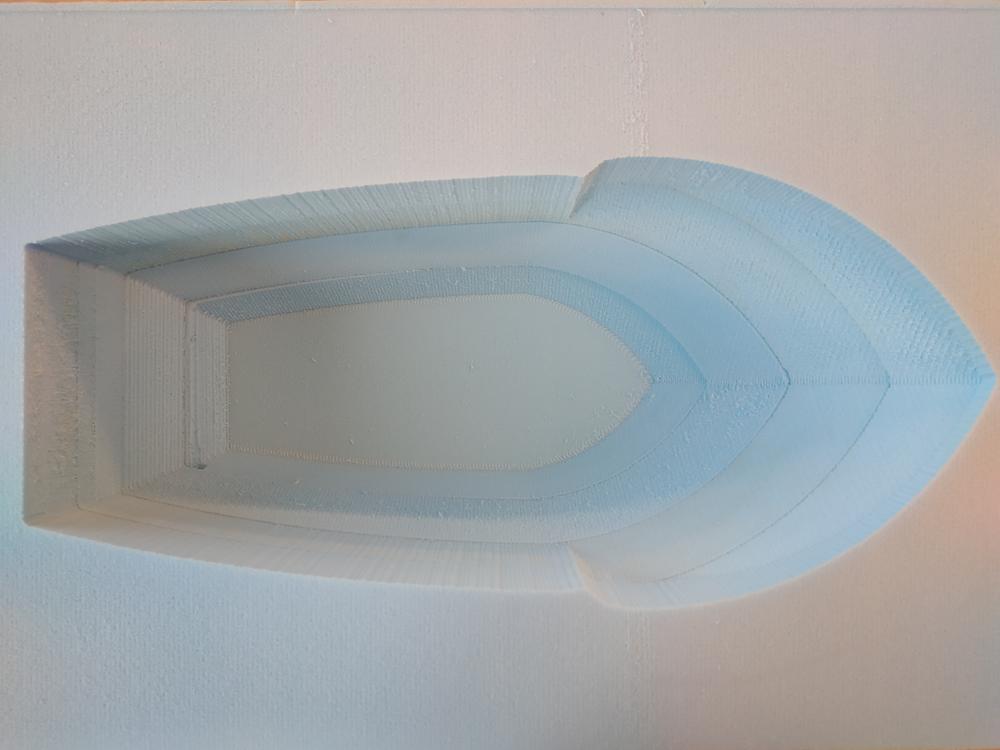
3D finishing toolpath for the second stock
 |
 |
3D roughing toolpath for the third stock
 |
 |
3D finishing toolpath for the third stock
 |
 |
NOTE : Here I saw that I made a mistake while making the mould in Fusion 360. Somehow the scale was not good. I modified the mold and check it twice in Fusion but now I have to machine the two missing stocks. This is how it looked.
I’ve done the modification on Fusion and machined the two last parts of the mould.
First the 3D roughing toolpath
 |
 |
Then the 3D finishing toolpath
 |
 |
3D roughing toolpath for the fourth stock
 |
 |
3D finishing toolpath for the fourth stock
 |
 |
Final result
Here what it looks whn I put the four parts on top of each other.
NOTE : I still have to fix the parts together, clean the edges and fix the small issue I had making the first part of the mold.

Ce(tte) œuvre est mise à disposition selon les termes de la Licence Creative Commons Attribution - Pas d’Utilisation Commerciale - Partage dans les Mêmes Conditions 4.0 International.