Week 18: Machine Design
2019.05.15
Group Assignments:
- Plan and make a machine: Document the group project and your individual contribution. Incomplete
Week 18 Contents:
- Introduction
- Building the machine
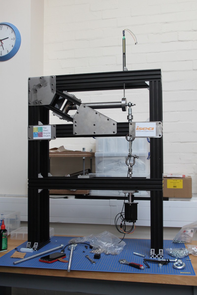
The Steel Bicycle Frame Testing Machine
Introduction
The machine we are going to build serves the dual purpose of being a submission for the Fab Academy, but also as a University of Brighton research project that will have a life after Fab Academy. Essentially it is a machine for testing the strength of welds on bicycle frames. The machine will apply a load (manually at first, but later through a stepper motor) and measure both the load applied and the displacement of the part. The initial aim is to get the machine to work at 1hz. We have received some sample items from various small bike frame builders.
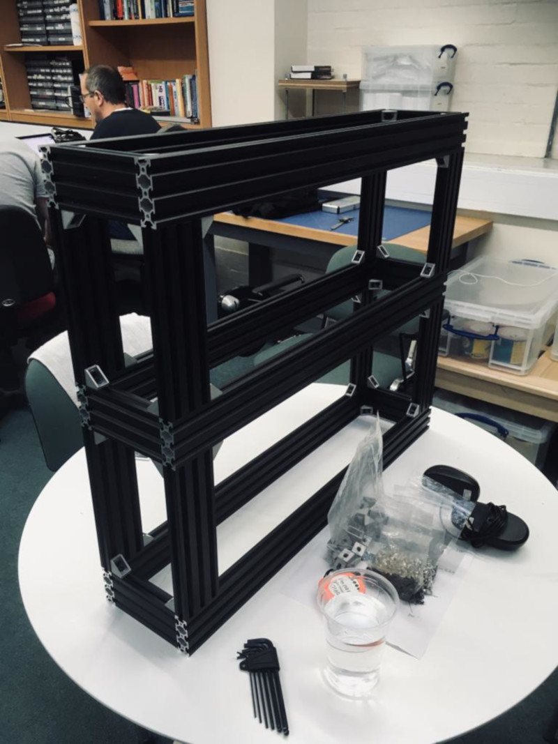
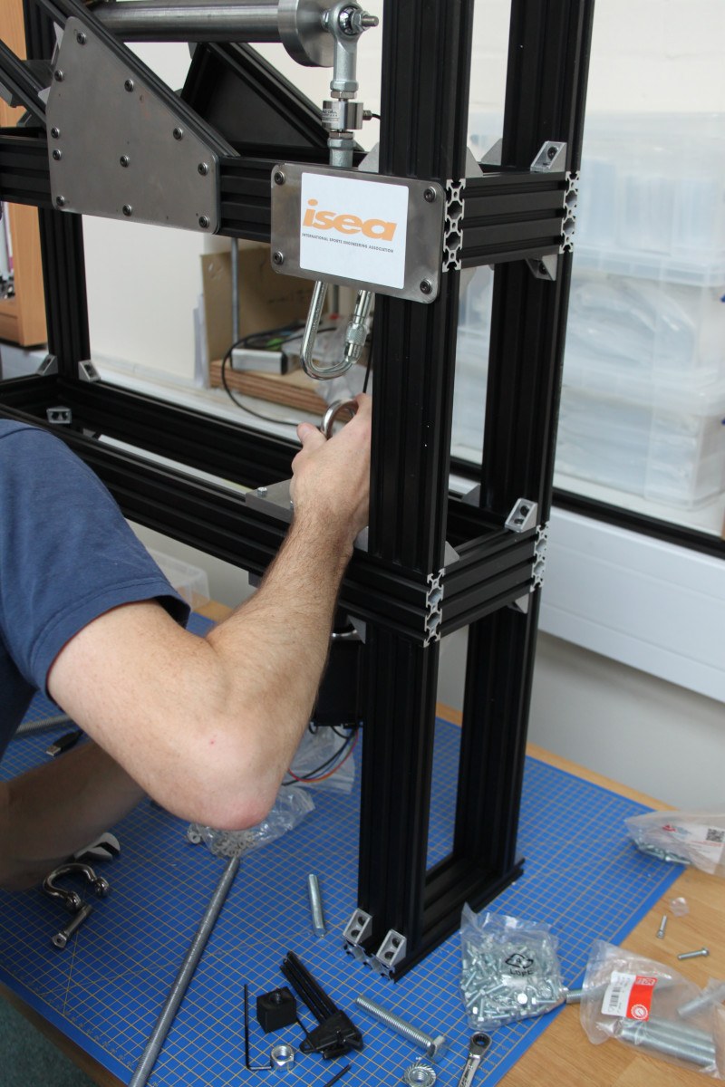
Constructing the frame
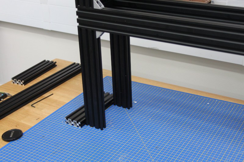
The frame of the machine is made from extruded aluminium (in a rather fetching matt black finish) joined with corner blocks that use bolts with special nuts that spin in to the channels on the extruded aluminium.
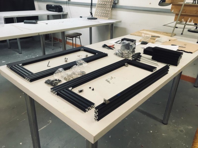
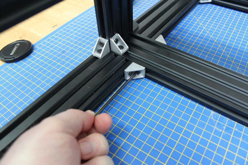
The initial layout of the parts, getting ready to start bolting them together. The bolts need 3mm Allen keys.
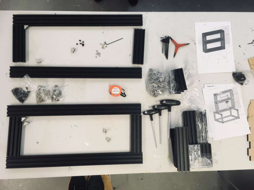
All the bits are ready - here's how it's going to work. The silver corner blocks are bolted to the extruded channels using nuts which twist in to the channel.
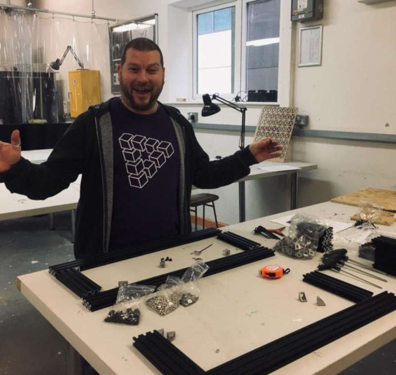
I'm excited to get started!
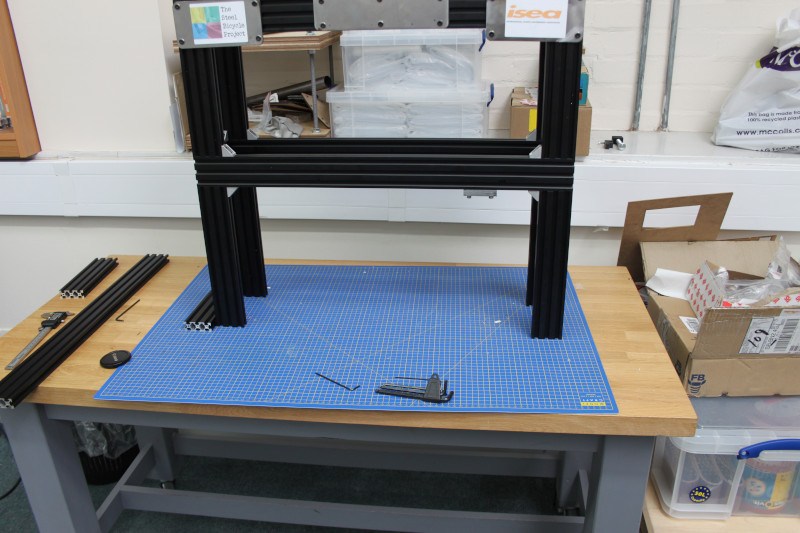
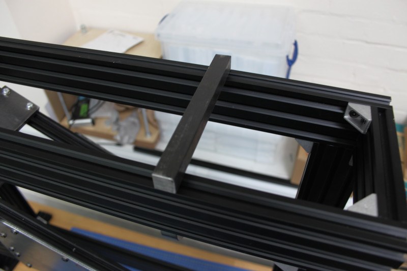
Using an engineer's square to make sure the frame is bolted straight. To build this first part I made two sides (the flat rectangles on the desk) and here you can see me attaching the spacers to give the frame depth.
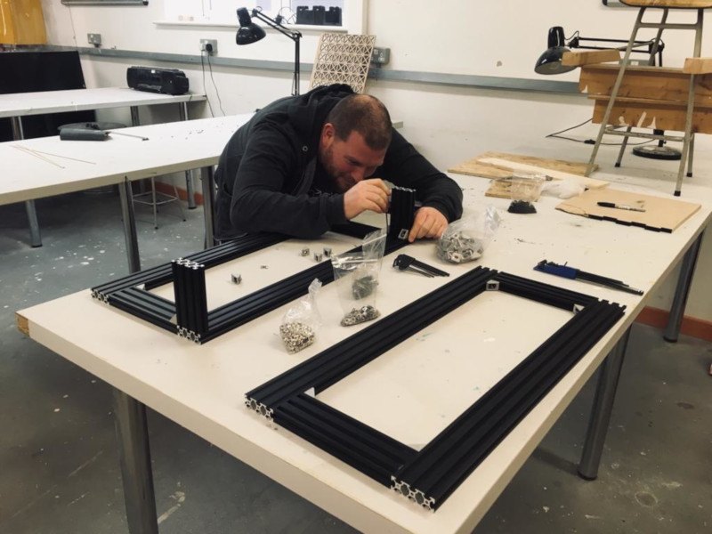
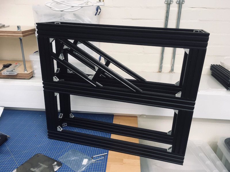
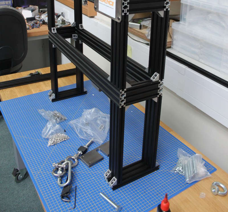
The frame with both initial boxes bolted together - the final machine will have a set of legs beneath these frames. The silver blocks are attached in every plane to give the frame strength.
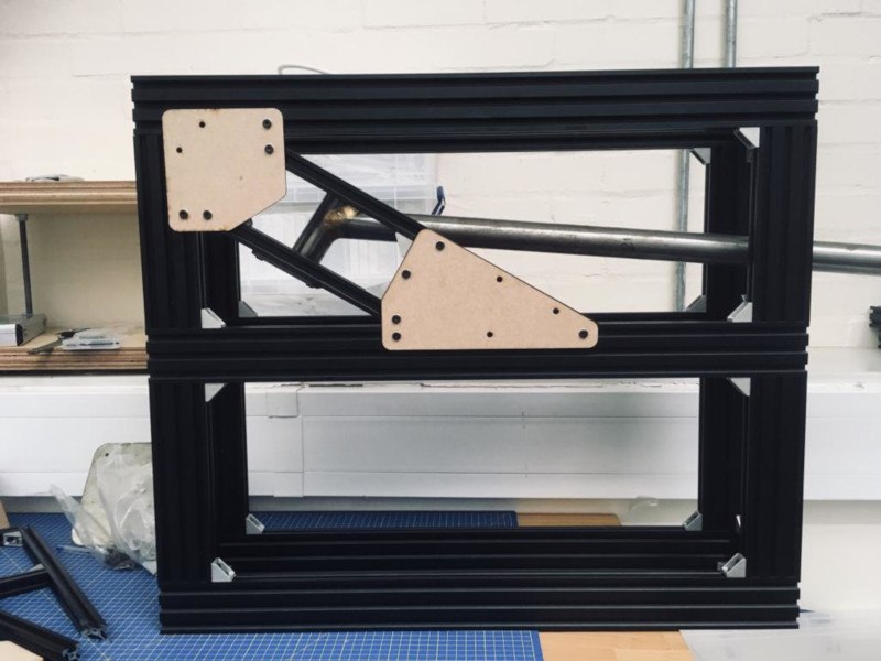
Making plates
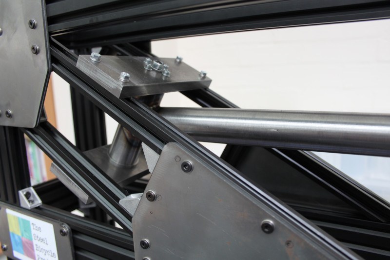
Des made these diagonals to hold the frame samples. In this image they are just resting on the frame, we will attach them using plates.
These MDF plates were used to make sure the plates would fit and after some small changes the plates were cut from metal. A steel frame sample is shown in the background - these will be cut down to fit within the frame.
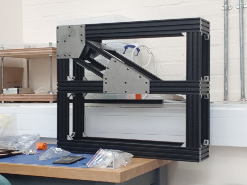
The plasma cut plates mounted to the frame:
Attaching the samples
The samples cut down to fit in to the frame are shown below. The holed circular parts are arbors designed to fit into the end of the smaller tube on the T-bar samples and bolt on to the plates mounted on the diagonals shown above.
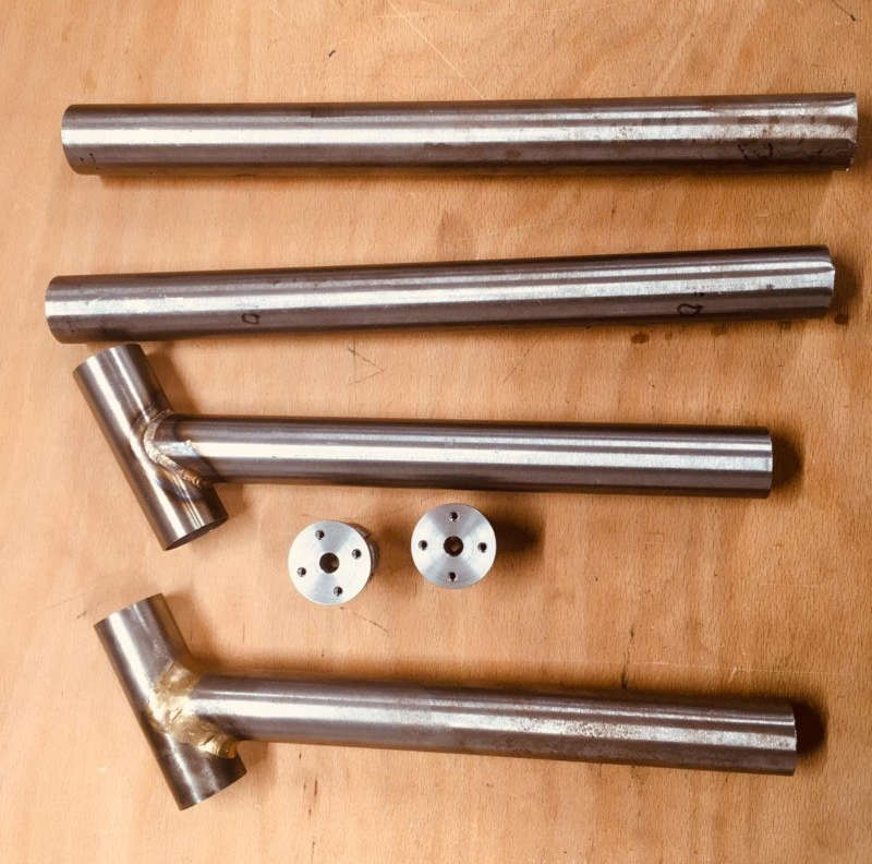
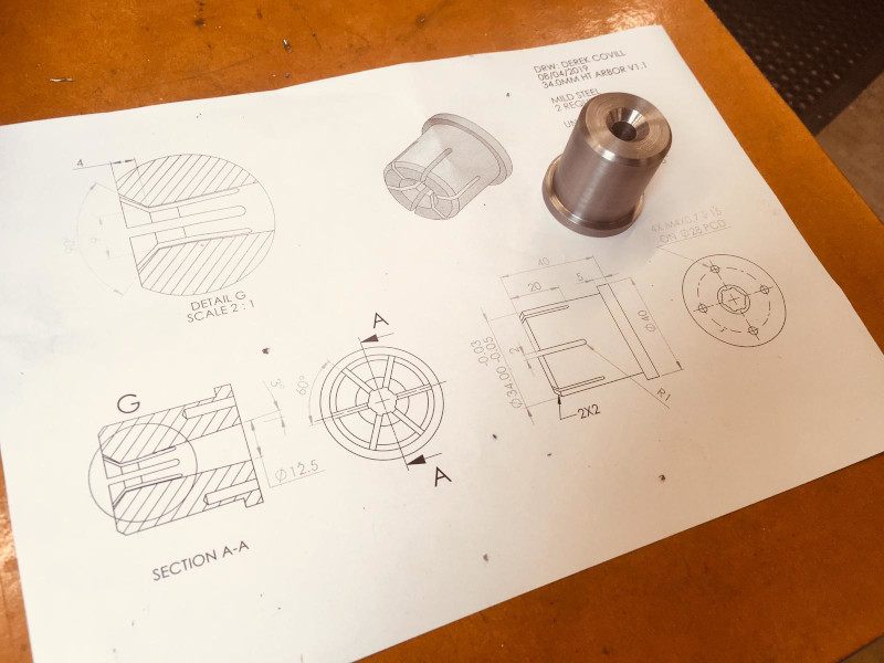
Drawing and partially made arbor for attaching the samples to the plates:
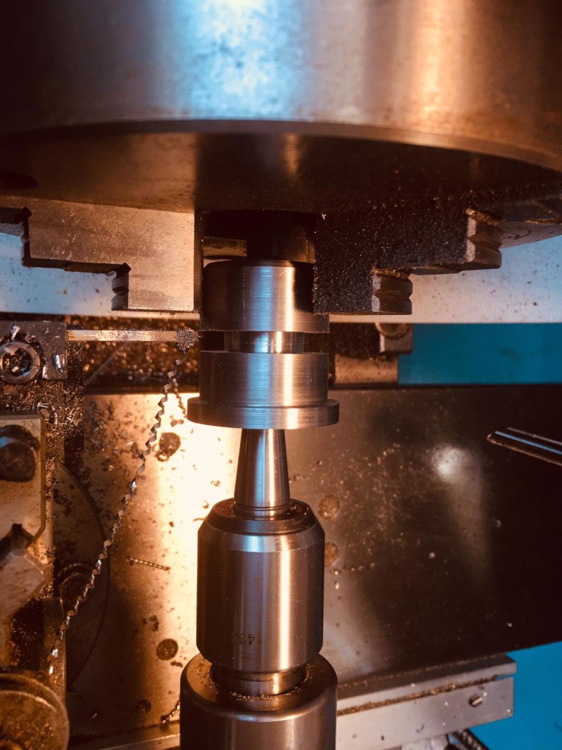
Here's the arbor being machined:
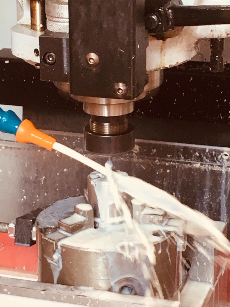
Arbor nearly finished:
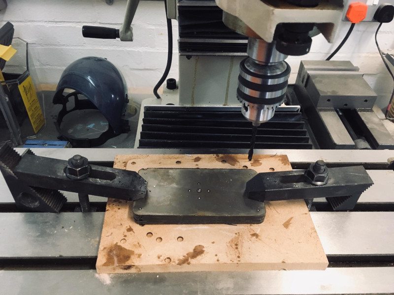
Here's the metal block about to be drilled on a mill. This is a service offered at the University and a technician drilled this for us:
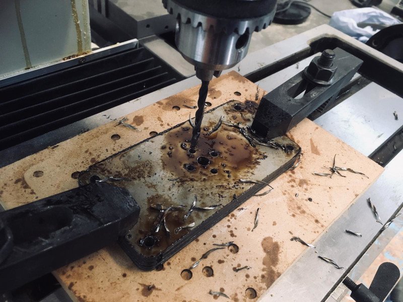
Here's the drilling in progress:
A sample in place, bolted to the plates being drilled above (but cut down slightly in a redesign). The arbors are inside the smaller tube on the T-bar.:
Fitting the legs
The legs are bolted on in the same way as the rest of the frame.
The feet plates are slightly longer than the width of the frame to add an extra bit of stability.
The legs raise the frame allowing the placement of the stepper motor:
Here is the frame with legs attached:
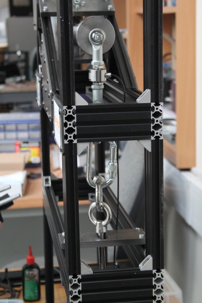
Connecting the load cell
For testing the machine we have connected various shackles to couple the stepper motor rod to the test sample via the load cell:
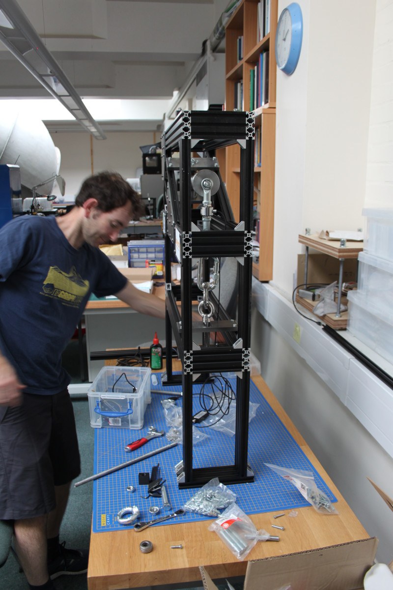
In this image you can see the 'expensive' (~£400) load cell connected to the sample via another arbor:
Calibrating and Testing the Displacement Transducer
This image shows the initial setup of the displacement transducer in progress. The power supply is clipped to four pin cables, powering the input board and the sensor at 5v. The FTDI cable is only connected to the TX and RX pins on my input board. The first time I got SoftwareSerial working on the board I was using the 3.3v FTDI cable for powering the board. The values I was reading kept skipping and missing line breaks. I have to admit that initially I blamed it on the SoftwareSerial, but later, in bed during my nightly 'think about ATtiny44s' session I realised that the microcontroller was not getting enough power. The next day in the lab I attached the board to a power supply and it sprang into life with accurate readings.
The power distribution was annoying with the crocodile clips slipping and the messy cables seen in the image above. To fix this I designed and milled a small power distribution board with a couple of pins for sensors too. I made large pads for the crocodile clips to connect to and added pins to supply Vcc and GND to the input board and the sensor.
This made the setup a lot neater and removed the need for a couple of power leads.
To calibrate the transducer I measured the readings at 10mm intervals along the sensor. I measured the 10mm increments with calipers.
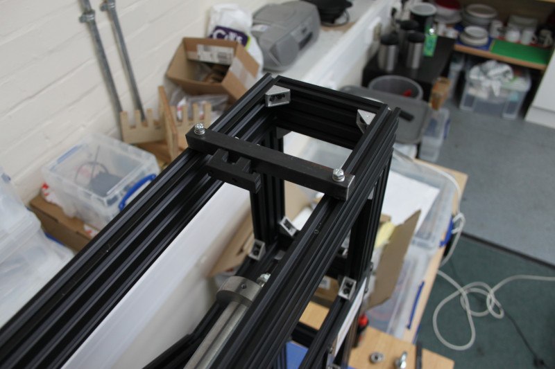
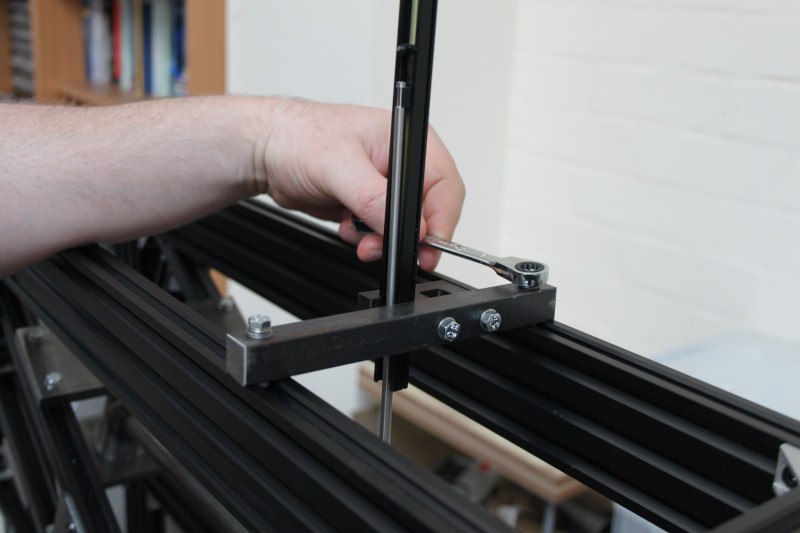
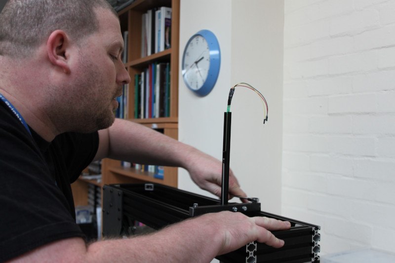
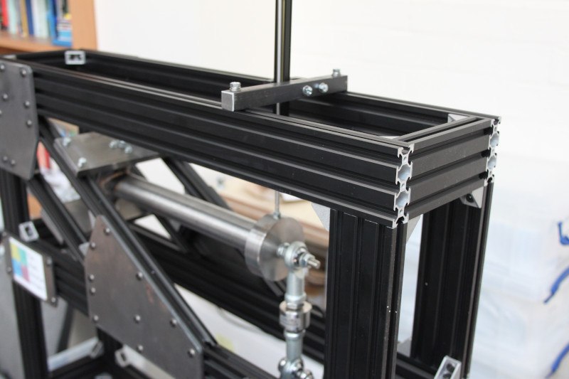
The next few images show the Fitting of the displacement transducer. There is a drilled metal bar that attaches to the channels on top of the extruded aluminium and has a small 3D printed bracket to hold the sensor. The arbor below the bracket has a small hole drilled to accept the rod from the displacement transducer.
Fitting the stepper
The stepper motor connected to the base, almost ready for testing.
Logging Data to an SD card
SD card module
The SD card is a 128GB microSD card connected through an SD card module. Note: The SD card has a 3.3v operating voltage, but the module has a voltage regulator and level shifter to allow the use of 5v.
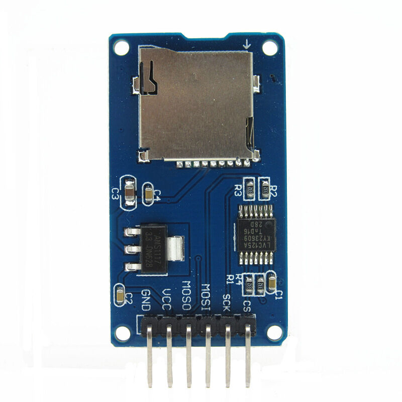 The connection of the module is quite simple and uses the ISP header pins. There are 6-pins on the module: GND and VCC to power the module, then 4 pins for SPI communication. MOSI (Master Out, Slave In, marked as MOSO on this particular module), MISO (Master In, Slave Out), SCK (serial clock) and CS (chip select in place of slave select). The printing on the module is slightly wrong, but it's easy to work out what they meant.
According to the Arduino site the "Serial Peripheral Interface (SPI) is a synchronous serial data protocol used by microcontrollers for communicating with" peripherals or other microcontrollers. It looks similar to the ISP (In-System Programming) pins (VCC, GND. RST, MOSI, MISO, SCK) but they are not the same. The SPI connection always has "one master device (usually a microcontroller) which controls the peripheral devices" (Arduino, 2019). The MISO, MOSI and SCK are the same on each device. The SS (slave select) line changes per device (the master enables or disables specific devices). "When a device's SS pin is LOW, it communicates with the master. When it's HIGH it ignores the master" (Arduino, 2019).
The respective Arduino pins are:
| Module Pin | Abbreviation | Arduino Pin |
| Clock select | CS | 10 |
| Serial clock | SCK | 13 |
| Master Out, Slave In | MOSI | 11 |
| Master In, Slave Out | MISO | 12 |
Formatting
Formatting the SD card needs to be done correctly for the Arduino to recognise the SD card. Windows will format anything above 32GB as exFAT - the Arduino can't read this. The card needs to be formatted as FAT32. The file names can only be 8.3 (example8.txt) else the Arduino returns errors. I don't usually say this, but I prefer to force the formatting in Windows Powershell - it is a lot easier than Linux fdisk which has way more control, but I don't really want it!
- Windows 10: Right click the Start button or press Win+X.
- Open PowerShell as admin.
- Use
format /fs:fat32 D:(replace D with whatever disk letter your SD card has been assigned by Windows).
Programming
The code opens a file object, starts serial comms and opens the stream to the SD card. There are lots of messages to explain what is going on - this is useful for debugging. In this demo version of the code I am just writing "this is the first line" and "this is the second line" to test that it works. In the final code I will write the data points from the displacement sensor.
#include <SD.h>
#include <SPI.h>

// Define the file object
File myFile;

// Set the chip select pin
int pinCS = 10;

void setup() {
// Start the serial communication
Serial.begin(9600);
pinMode(pinCS, OUTPUT);

// SD card init
if (SD.begin())
{
// Message
Serial.println("SD card is ready to go...");
} else
{
//Message
Serial.println("SD card initialisation failed.");
return;
}

//Create the file
myFile = SD.open("data.txt", FILE_WRITE);

if (myFile) {
// Message
Serial.println("Writing to file...");

// Write to the file (data from sensor goes here)
myFile.println("This is the first line.");
myFile.println("This is the second line.");

// Close the file
myFile.close();

// Message
Serial.println("Done.");
}
else {
// Message
Serial.println("Error opening file.");
}

// Read the file
myFile = SD.open("data.txt");

if (myFile) {
// Message
Serial.println("Read from file:");

while (myFile.available()) {
Serial.write(myFile.read());
}
myFile.close();
} else {
// Message
Serial.println("Error reading file.");
}
}

void loop() {
}
Board for reading the data
Constructing the frame
References
Online
- The Fab Charter [Accessed 30 Mar. 2018].