Week 8: Computer-Controlled Machining
2019.03.06
Individual Assignments:
- Make something BIG! Complete
Group Assignments:
- Test runout, alignment, speeds, feeds and toolpaths for your machine. Partially Complete
Week 8 Contents:
- What I learned this week:
- Downloads
- References
Subtractive Machining
Using the CNC
Using a spinning tool called an end mill, subtractive machining removes material from the workpiece to produce a form (Rohrbacher et al, 2017). While the end mill looks similar to a drill bit on first sight, it is a different tool. "A twist drill is designed to cut axially, with a pointed tip that plunges directly into the material" (Rohrbacher et al, 2017). The drill sides are helical flutes that spiral removed material upwards, out of the way of the cutting tip. The purpose is to create as circular a hole as possible down in to the material. The sides of a drill bit are blunt, only the tip of the drill "has cutting surfaces, one on each side of its centre axis" (Rohrbacher et al, 2017). The flutes on the twsit drill are only for material removal and this is a major difference: "The flutes of most end mills also have sharp bottom edges that allow them to plunge" (Rohrbacher et al, 2017), but the helical flutes on the sides of the end mill are also sharp allowing the bit to cut material laterally. Instead of only plunging down into the material the end mill can cut a channel the width of the tool (plus any run out), referred to as the kerf. The depth of this channel is important - the end mill will snap if you try to move it too deeply through solid stock. To get to the 10mm plunge required in the example image below, the end mill could make, for example, 5 passes plunging 2mm further each pass. The feed is also important. This is the rate at which the cutting tool is moving, normally expressed in mm/s. The speed of the tool is the rotational speed of the spindle and by extension, the tool. The tool trying to cut 10mm directly in to the stock in diagram A below is liable to break. Diagram B shows the first pass, a much shallower cut of 2mm. The path would be repeated 5 times to get to the depth required of 10mm, but in smaller increments to lower the risk of snapping the end mill. The speed and feed need to be adjusted to get an optimal cut, but the lateral movement is less likely to break the tool. In commercial settings with time and money implications then the depth of the cut would need to be optimised, but for my more leisurely cutting I can afford to be conservative with regards to the depth of the cut.

Corner Problem
A circular cutter cannot properly mill out an internal corner because the tool's shape doesn't allow it. On the external corners the tool can produce a pointed 90 degree shape as the cutter can run past the point of the corner in both directions. On the internal corner the cutter can only run as far as the adjacent face allows, leaving a rounded shallow that cannot be cut. The image below shows the toolpath of an end mill from above, showing the issue. The small shaded areas at the bottom of the image are parts of the material that were intended to be removed, but the tool cannot reach them.
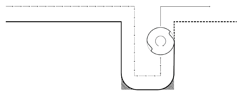
If, for example, this same slot was cut in another piece of material and the two were intended to slot together, the pieces would not fit flush as the rounded corners at the bottom would interfere. A solution for this problem is to fillet the internal corner. There are various methods for doing this (sniglet, t-bone, dog bone). The t-bone fillet is shown below:

The red dashed box shows the now flat base of the slot. This is possible because the tool has been able to move past the point of the corner.
Toolpaths
The three most basic toolpaths are profile, pocket and drill. "A profile toolpath follows a line of an individual part. It’s the digital equivalent of cutting a pattern by hand. Profile toolpaths, or profiles, cut around a closed shape to a specified depth (Rohrbacher et al, 2017)".

"A pocket toolpath cuts on the inside of a closed line or shape, removing all the material within the pocket (the recessed, cleared area) to a user-specified depth. Pocket cuts have vertical sides and a flat bottom (Rohrbacher et al, 2017)." and finally the drill toolpath "cause[s] the CNC to operate like a drill press, plunging the end mill vertically into the material (Rohrbacher et al, 2017)."
Spirograph Project
Using the AXYZ Machine in Grand Parade
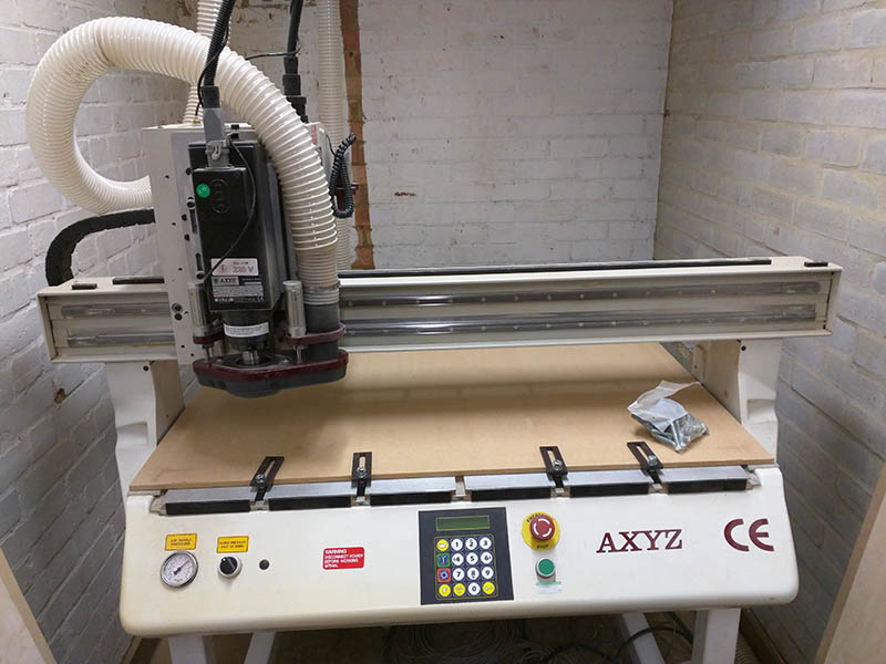
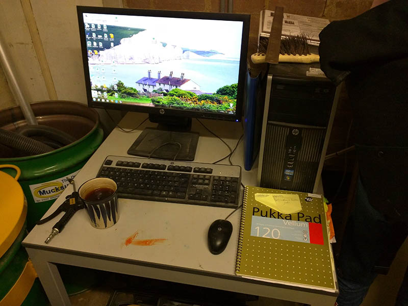
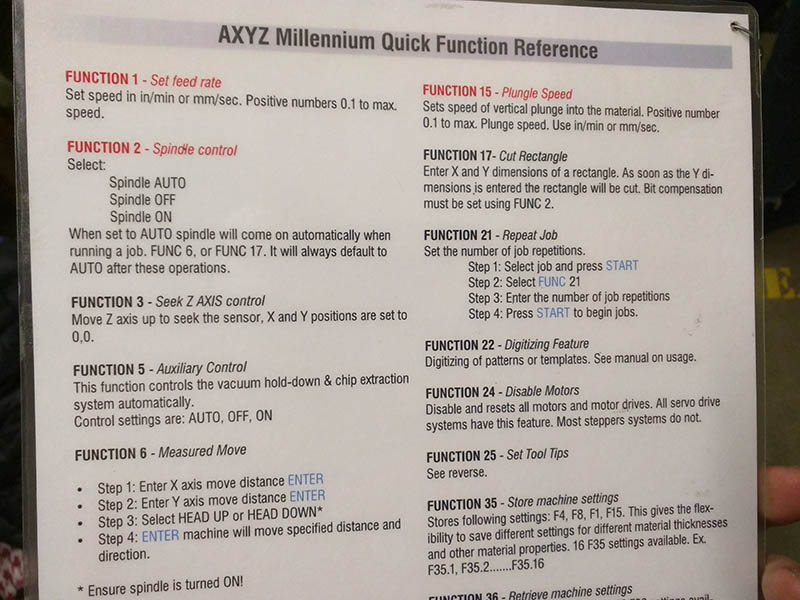
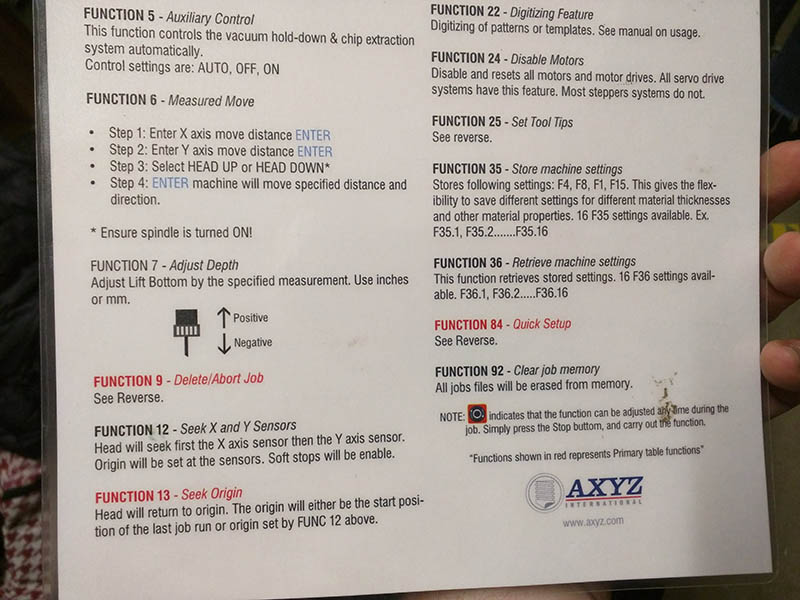
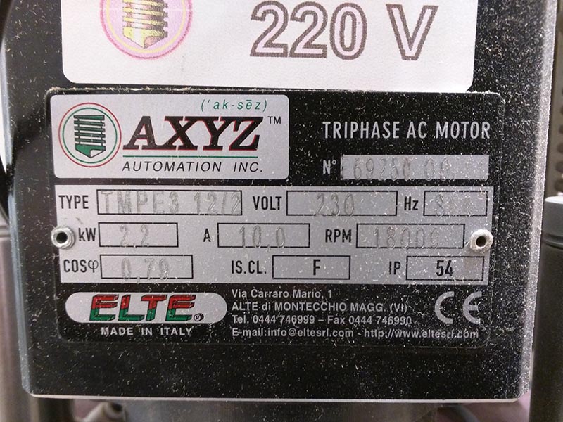
The machine at the Grand Parade campus is an AXYZ Millenium router table.
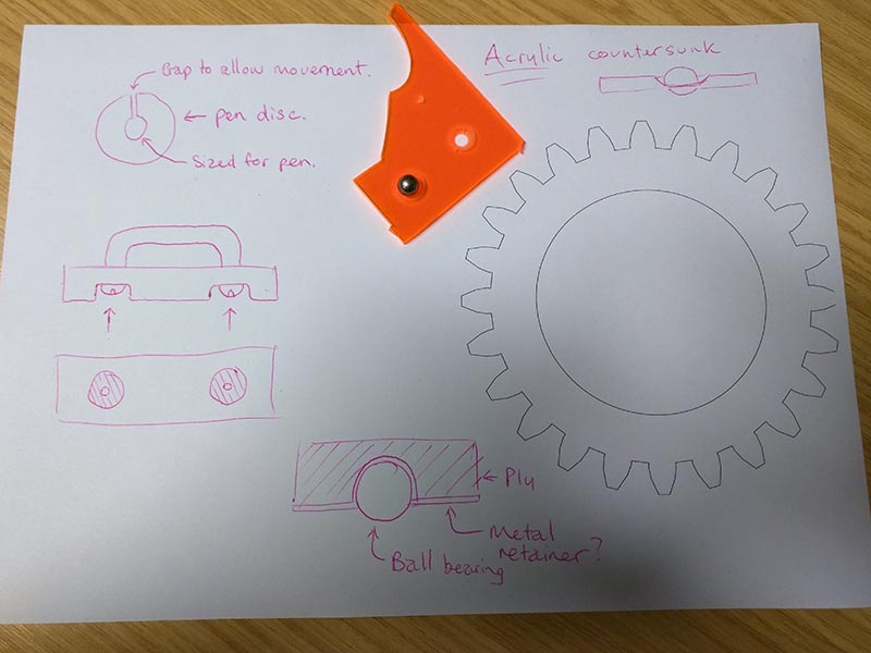
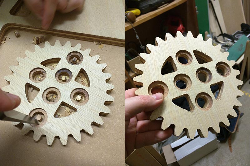
My initial idea for this week's assignment was a large hypotrochoid art set (commonly known as a Spirograph). I imagined it could be used to draw large chalk art in the street. I considered the friction of the large pieces of wood and thought that I could negate that to a certain degree with ball bearings supporting the cogs. I cut some smaller versions of the kit using 2mm MDF as a test. It was hard to use because you can't see through the cogs. I remade it from transparent 2mm acrylic and found it much more useful. I moved on to cutting a large version of the smaller, internal cog, with some trepidation - the opaque cogs from the smaller kit was not a good indicator. After seeing the first cog cut from 18mm, feeling the weight and holding it in my hand I realised that it would be highly impratical to use, especially for my young nieces who I had in mind as potential users. I've documented the process here anyway, showing the use of the AXYZ machine, but a different project (baby stool) is documented afterwards.
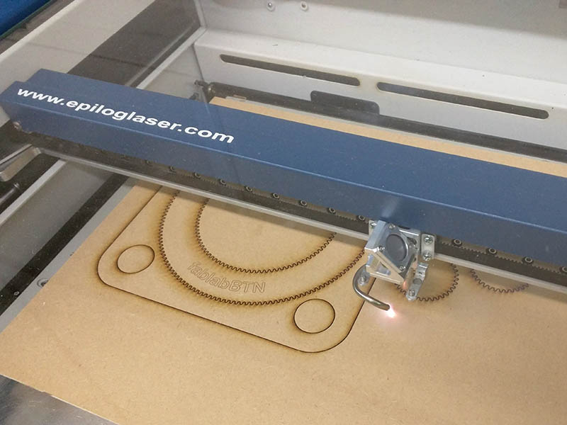
Cutting the small test pieces on the laser cutter:
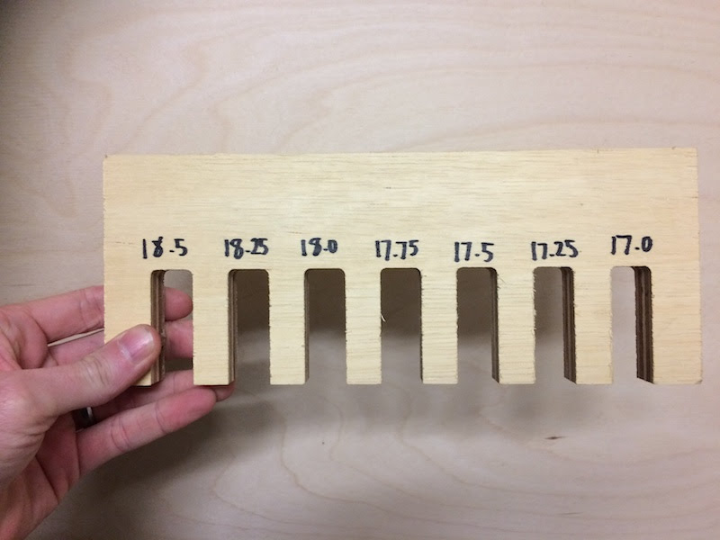
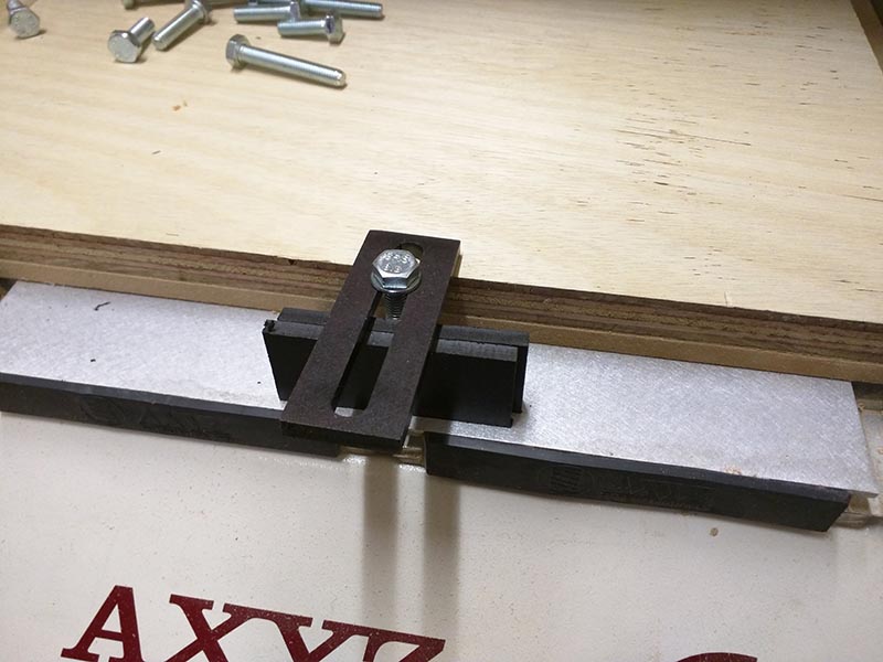
The group as a whole cut two of these kerf bars from the machine to test the fit of parts cut from this stock. It is ostensibly 18mm ply.
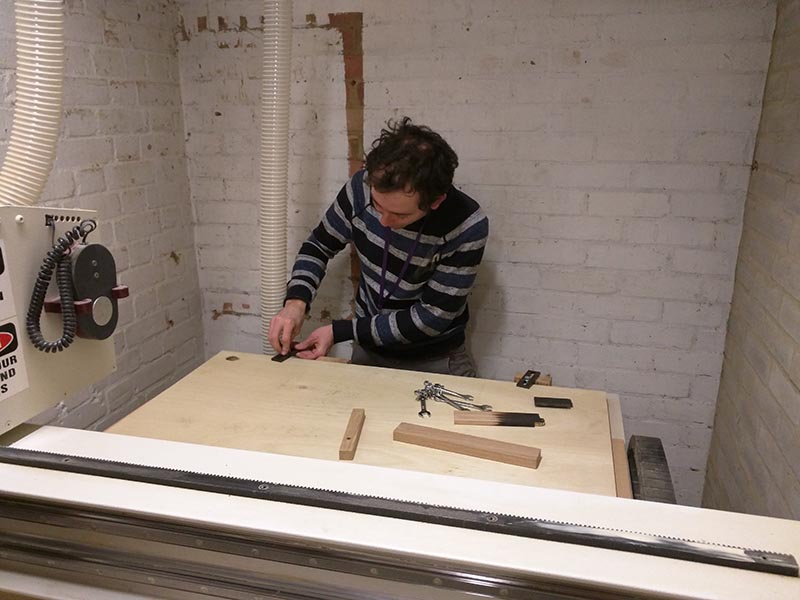
When using the machine the spindle is capable of 18000 RPM and wood chips thrown from the machine, or worse, shrapnel from a broken tool could cause severe injuries to the eyes or face. This personal protection equipment was provided for use with the machine. I provided the rakish stare myself.

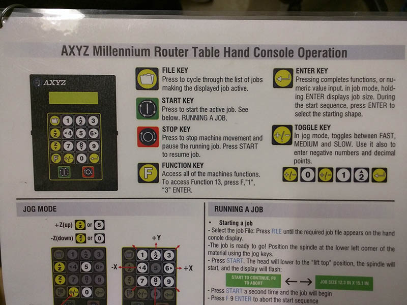
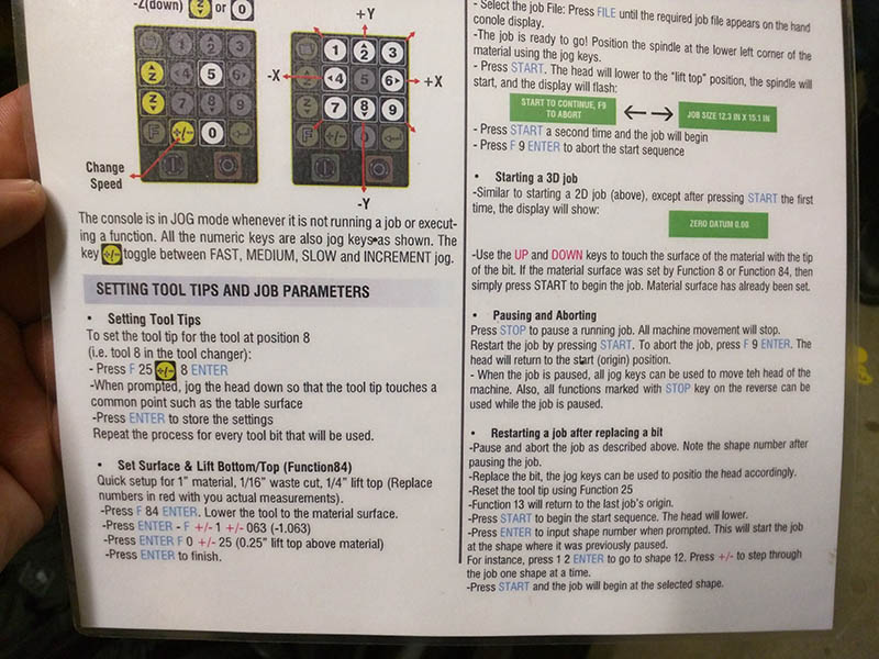
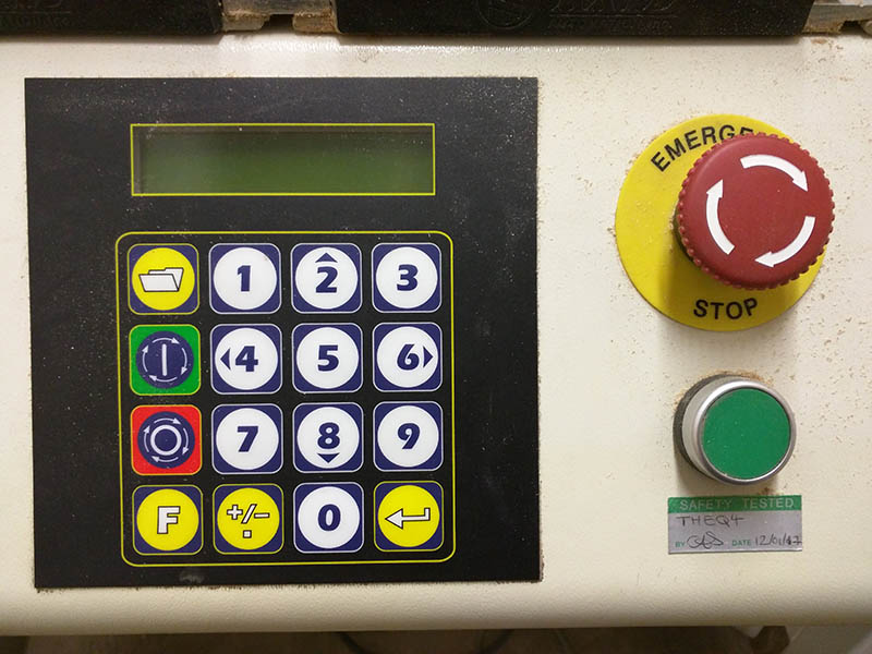
The instructions for the machine are detailed below. It works with a series of functions.
Obstacles
Problem 1
Stool Project
Using the E28 machine in Heavy Engineering/Creativity Suite.
Replace text.
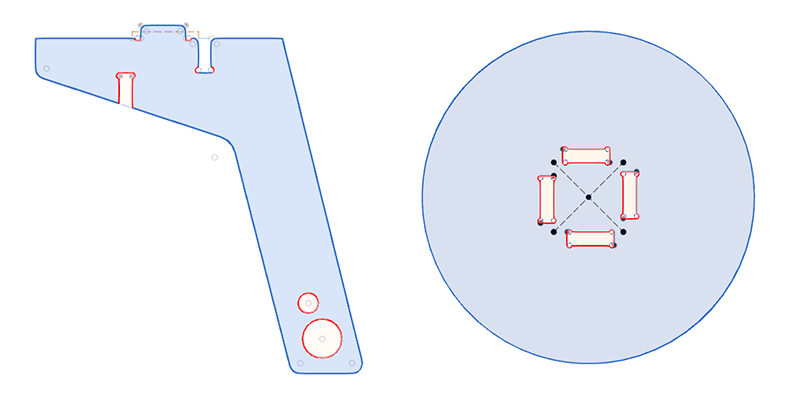
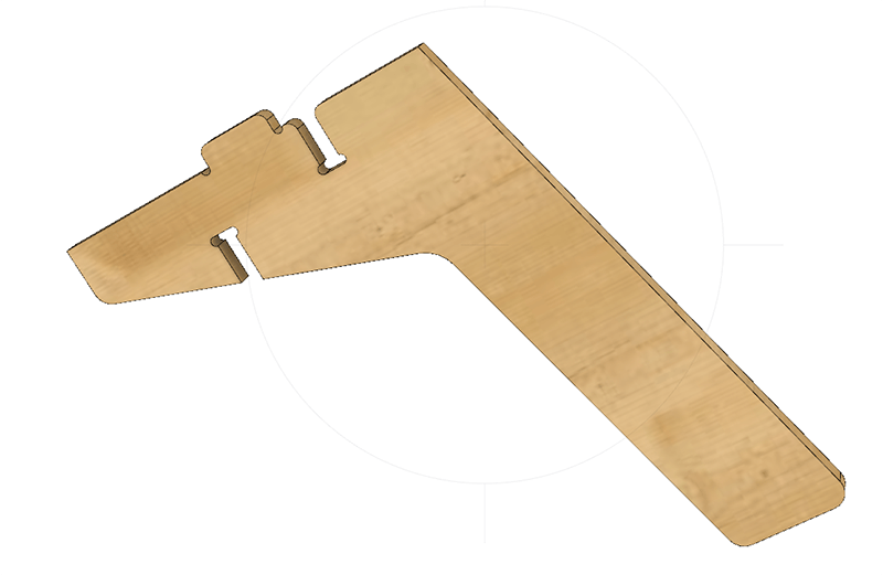
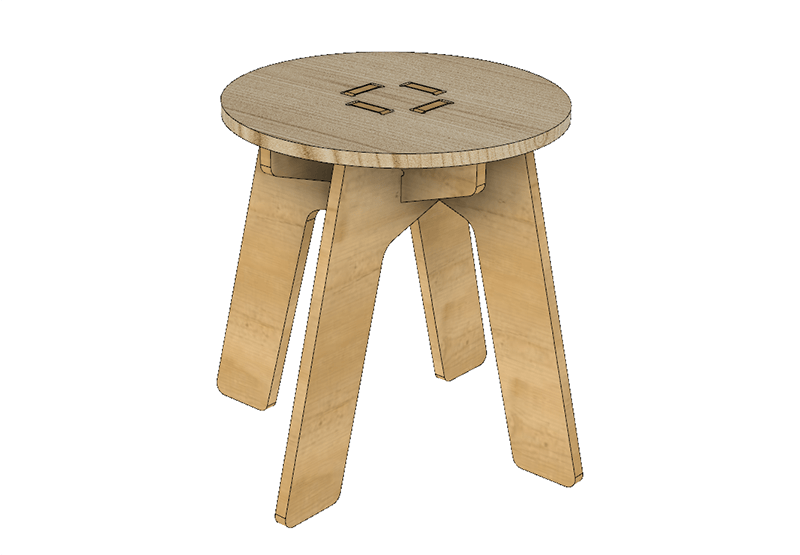
Here's an animation showing the final render with an extra fillet around the edge of the seat top. I quite like the shape created by the legs, but I think the stool probably uses too much material. I think I could make some improvements here.
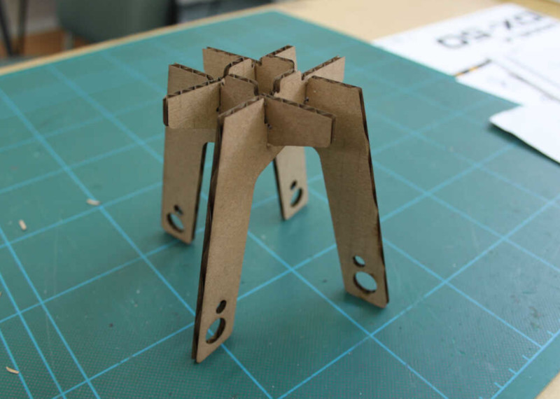
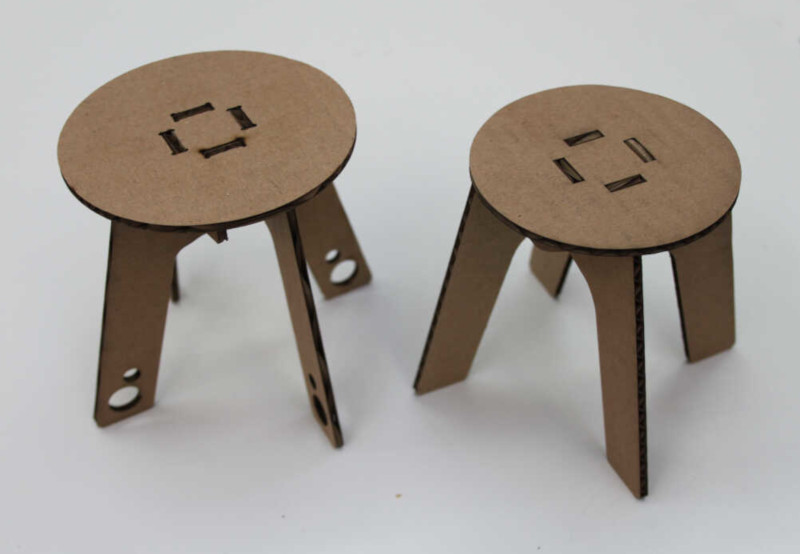
I lasercut a couple of test pieces, changing the dimensions slightly until I was happy:
The parametric model of the stool made it really easy to change the slots to the thickness of the material.
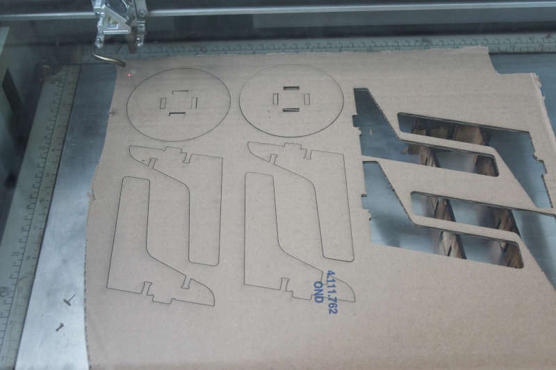
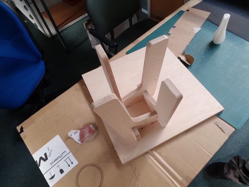
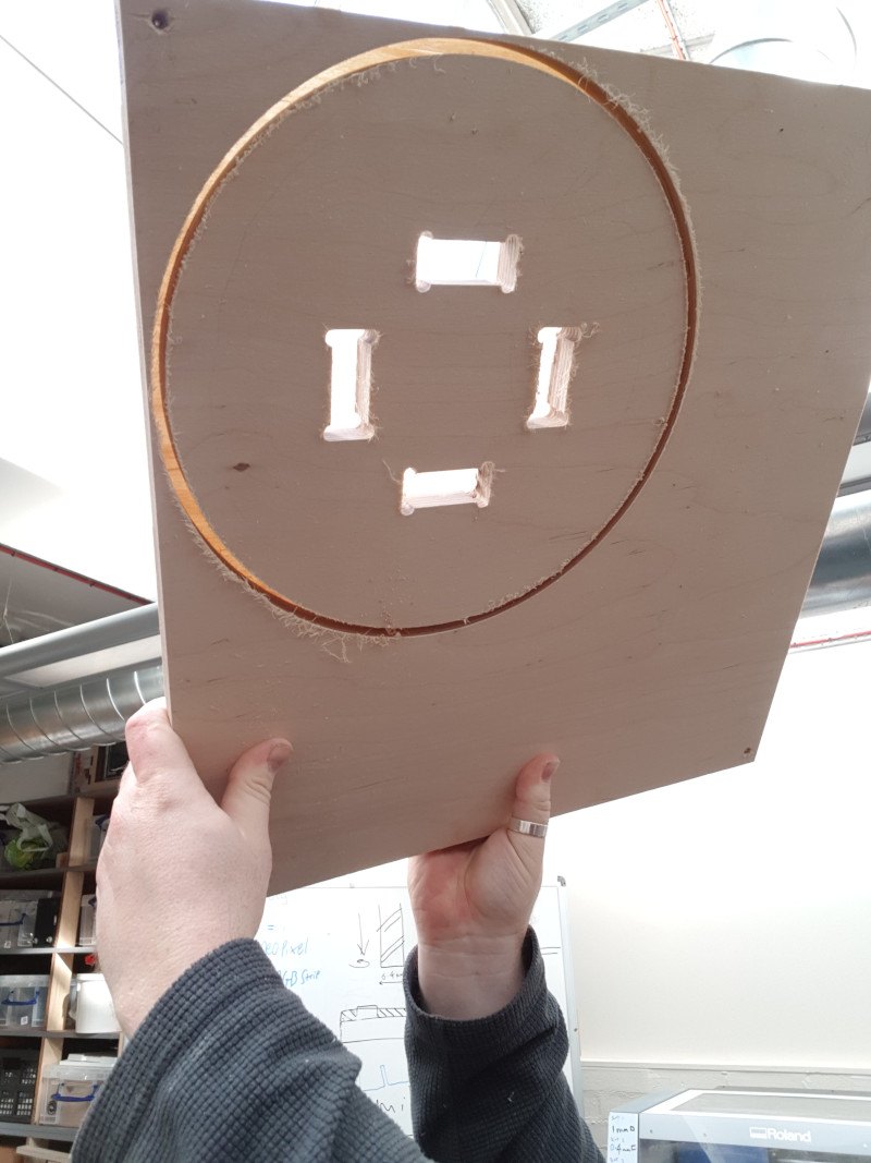
The legs cut went all the way through the ply and came out nearly finished, requiring only a quick sanding. This image shows the seat top still attached to the board it was cut from and I put the assembled legs in to test the fit.
Here you can see the last ply layer still connected to the board and the seat top. I'm not sure what happened, but the final 1mm was not cut from the outside. The slots inside went all the way through. I used a carpet fitters knife to slice the last layer close to the edge of the stool top and then sanded the edges. It came out well.
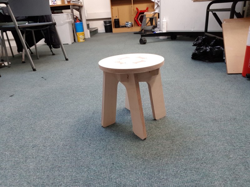
Here is the stool connected together
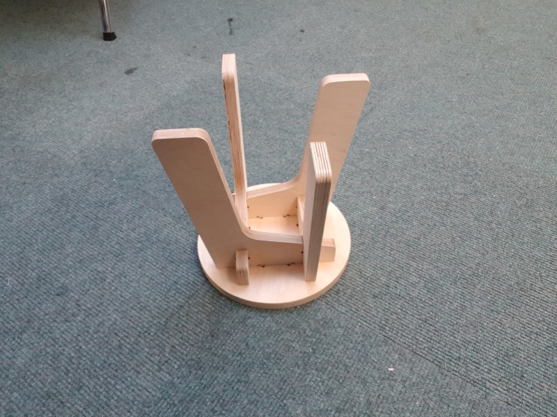
The legs were difficult to fit together - the last one needed to be pushed close to fitting and then hit with a mallet to make it fit. It could be solved with a slight widening on the last slot on the last leg, but that removes some of the simplicity of the design. I had made some cardboard tests and not even considered the fact that the cardboard had more malleability than the plywood. The test stools went together very easily and I didn't consider the fact that this might not be true for the wooden versions!
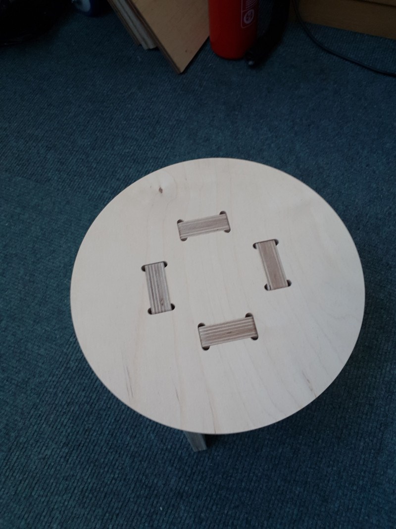
The top fits really well and grips the tabs on the top of the legs. I think my niece will test it to destruction, so I will glue it before I hand it over, but I was pleased with the press fit tolerances.
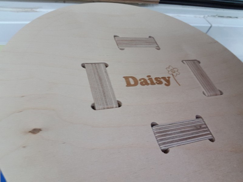
I used laser engraving to personalise the stool for my niece. This was slightly nerve-racking as I only had enough wood to make one stool top. If this went wrong, it was the end of the road! I practised on a piece of cardboard to make sure I was correctly positioned and took a deep breath. It worked out fine!
Downloads
Right-click and choose 'Save Link As...' or similar to download.
Baby Stool
Baby Stool: Fusion360 Archive (419KB)
Baby Stool: Leg Solidworks Part (33KB)
Baby Stool: Top Solidworks Part (33KB)
References
Online
- The Fab Charter [Accessed 30 Mar. 2018].
Offline
- RohrbacherFilson, A., France, A., Young, B. and Kaziunas, A. (2017). Design for CNC. Sebastopol: Maker Media, Inc.