Week 7: Electronics Design
2019.02.27
Individual Assignments:
- Redraw the echo hello-world board, add (at least) a button and LED (with current-limiting resistor), then check the design rules, make it, and test it. Complete
- Extra credit: simulate its operation. Incomplete
- Extra credit: render it. Complete
Group Assignments:
- Use the test equipment in your lab to observe the operation of a microcontroller circuit board. Complete
Week 7 Contents:
- What I learned this week:
- Obstacles and Solutions
- Downloads
- References
Installing Eagle
For Windows and Linux
Eagle was easy to install on both systems. The Windows download is available from the Eagle website. Once downloaded I ran the installer and followed the prompts. I already have an Autodesk account from using Fusion 360 and once my logged in Eagle sprang to life.
The Linux install was completed using trusty old apt-get: $ sudo apt-get install eagle
The interfaces are practically identical in the Windows/Linux versions.
Designing with Eagle
Create a Project
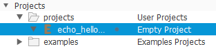
This week I started off by following this Sparkfun tutorial to get a feel for Eagle. I really enjoy learning a new piece of software and the little successes you get along the way. First of all I opened the 'Projects' folder in the Eagle control panel, then I right-clicked on the 'projects' folder and selected 'New Project'. I named it 'echo_hello.world'. Eagle creates a folder in the default project folder (on Windows this was Documents > EAGLE > Projects and on Linux it was ~/EAGLE/projects/). Looking at this in the file system it reveals an 'echo_hello.world' folder with a .epf file.
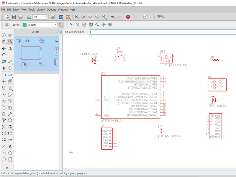
I then created a 'New Schematic' by right clicking on the empty project 'echo_hello.world' folder and selecting 'New >'. This opens the schematic window:
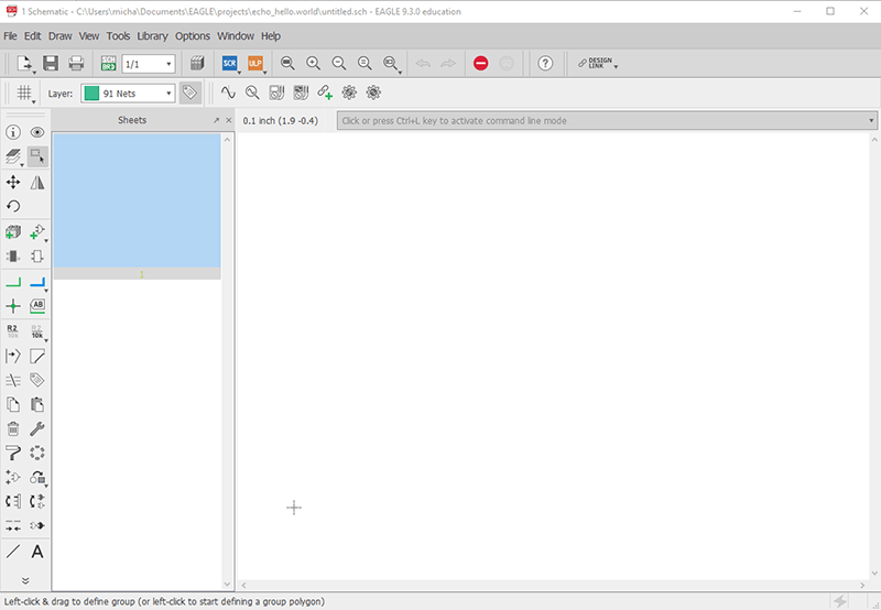
'Schematic design is a two step process. First you have to add all of the parts to the schematic sheet, then those parts need to be wired together' (Sparkfun, 2019). I got a very helpful tutorial from Andrew, a FabAcademy graduate and Des, our instructor suggested I should introduce components slowly, making all the connections as each component is added. I'm going to try that method first.
The Eagle interface is fairly intimidating to begin with. It is awash with icons and buttons, all adorned with unfamiliar symbols. The first button I need is the 'add component' button.

Clicking on this brings up the 'add' dialogue - this allows a search of all the active libraries.
Libraries for Eagle
What is a library?
A library is an XML document which lists components. The listing for each part in the library describes the parts, giving a part name and value, describing the package size and giving notes. Images for the schematic and a pad layout for the board view are also included. The libraries can be obtained from various sources - you can download an XML document and include it, you can create your own, there are Eagle provided libraries and there are libraries for most of the large vendors.
Adding libraries
The Fab Academy library is available here.
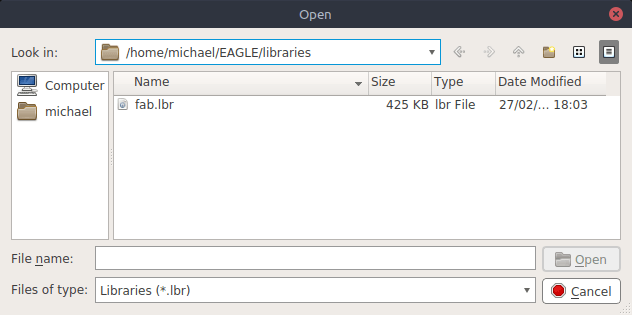
To add a downloaded library to Eagle first I placed the file in the Eagle > Libraries folder. (I found it bizarrely difficult to download fab.lbr for a number of reasons and ended up copying and pasting the raw XML in to a new file in my Eagle > Libraries directory). Then I opened the library using Library > Open Library:
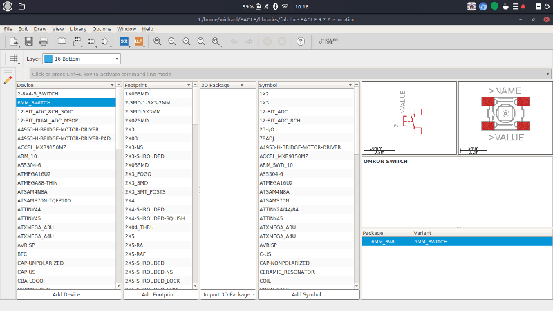
I selected the (only) local library in the directory and opened it. This brings up the library view, showing all the parts and various information about them. It also shows an image of the schematic symbols and the pad layouts:
The parts I used:
| Symbol | Name | Notes |
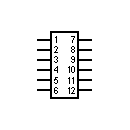
|
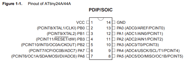
Microcontroller | The microcontroller is the computational device that can be programmed to operate in different ways. In this board it is an ATTINY44, but there are hundreds of different microcontrollers. |
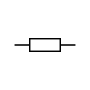
|
Resistor | A resistor provides resistance. Resistance, it turns out, is not futile. They are used for many different tasks, but one task on this board would be as protection for the LED. Without a resitor to limit the current the LED would burn out. |
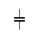
|
Capacitor | A capacitor holds charge. It is like a small, quick-charging battery. Capacitors can be used for many things - providing a 'smooth' electrical signal is one example. |
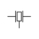
|
Crystal | A crystal resonates at a certain frequency and is therefore able to provide timing for your circuit. Crystals come in a variety of accuracies and frequencies. The one used on this board is 20Mhz. XTAL is a short name for crystal used on the board. |
|
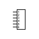
Header | A resistor provides resistance. They are used for many different tasks, but one task on this board would be as protection for the LED. Without a resitor to limit the current the LED would burn out. |
|
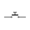
Switch | Omron Switch. In the fab.lbr it's know as the 6MM_SWITCH. The switch is a momentary switch, meaning it springs back to its original state once it is no longer being pushed. A keyboard key is another example of a momentary switch. |
The search in Eagle gives the following advice:
The wildcard character '*' matches any number of non-whitespace characters, while '?' matches exactly one of these characters.
If Pads is checked, devices that contain PADs will be included in the search.
If Smds is checked, devices that contain SMDs will be included in the search.
If attribute search patterns 'name=value' (e.g.: tolerance=5%) are given, these patterns have to match additionally. An attribute search pattern without the character '=' is searched in the attribute names and values.
To find all NAND devices from the 74xx series, enter: 74* nand
Turn on the grid
The grid is really useful and opened up a lot of new learning for me! Being a European I have a long standing affinity with the metric system. I am even more metric than your average Englishman, due to living in the Netherlands until I was 12. I basically consider the Imperial system historical. I have a very nice socket set which includes these alien fractions that seem so hard to deal with, but since my motorcycle is Japanese I have never touched an Imperial socket and, frankly, have never wanted to. Eagle has forced me to learn about inches.
I clicked on View > Grid to bring up the grid dialogue:
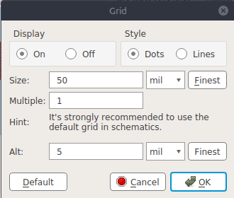
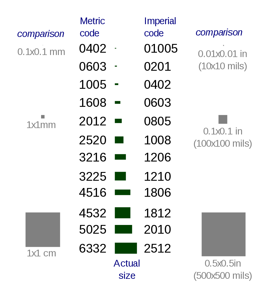
It starts off exactly as confusing as I always thought it would be: The word 'mil' is not short for 'millionth', but rather taken from the same French root that gives us millipedes and millimetres (even more confusingly). It actually means thousand, so a 'mil' is 1/1000 of an inch. Unfortunately everyone here in Europe immediately thinks you mean millimetres when you say 'mil'. A millimetre is in fact 39.3701 mil and 1 mil is 0.0254 mm. So, that's cleared that up.
I think if I spend a long time with Eagle I shall configure it with metric measurements, but for now using 'mil' is the easiest as the pads for the parts are spaced using thousands of an inch. The pads on the header are 100 mil apart, the default grid size is 50 mil, so everything fits nicely and allows a trace to be routed on the centre of the gridline between two pads.
My first attempt at joining up the schematic.
Here's the board generated by the above schematic showing all the basic components. I picked a weird header from the library first of all, this has been changed in all the other images.
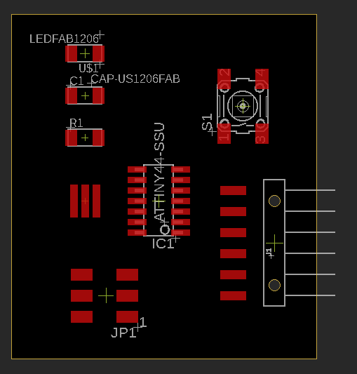
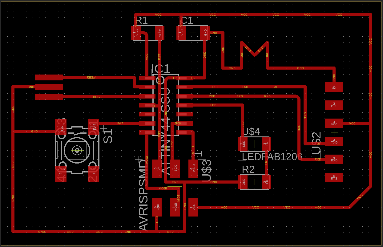
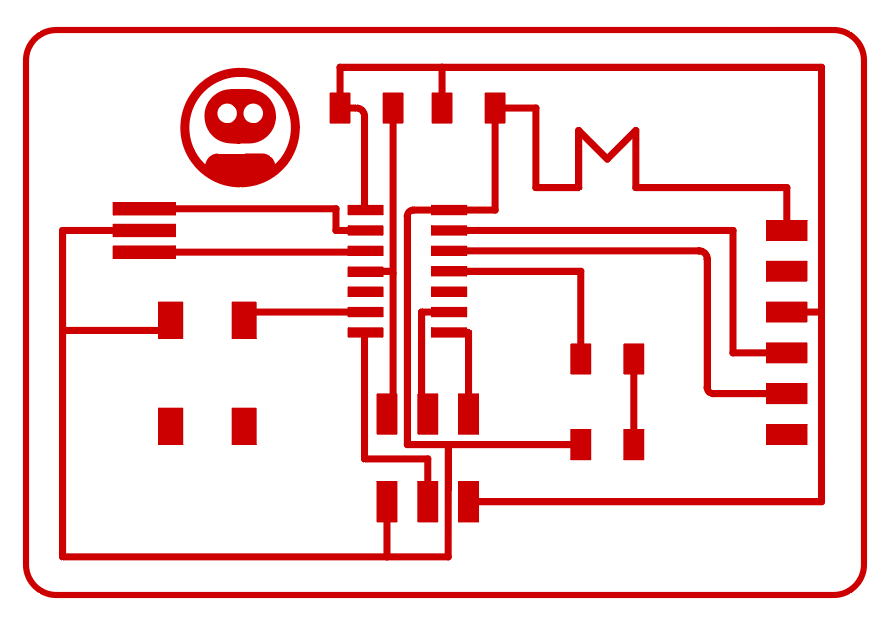
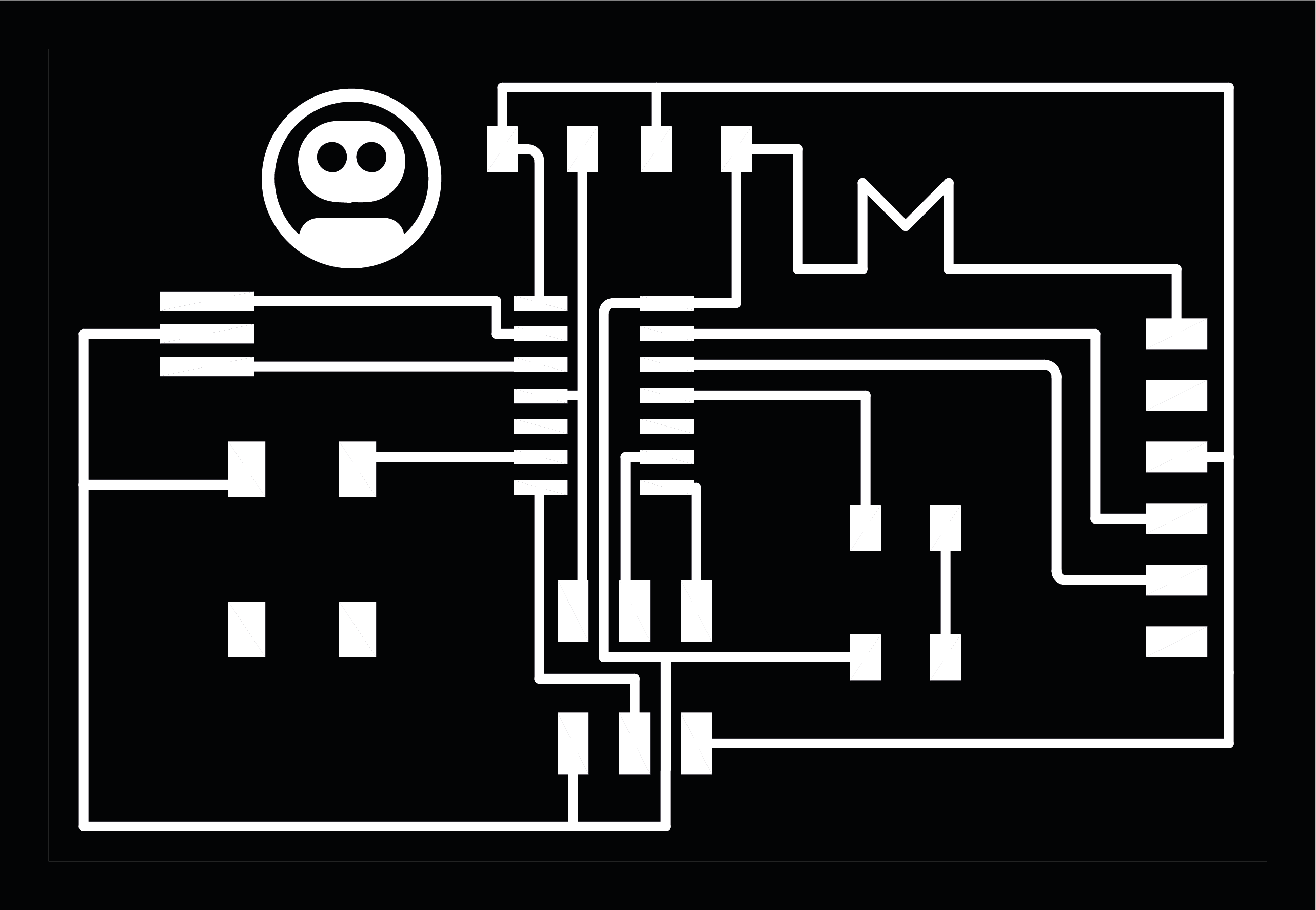
I went away for the weekend to Dorset, to stay in a cottage with some friends. I was a bit worried I wouldn't have enough time to get everything done this week, but the ridiculously slow train from Brighton to Dorchester took 4 hours. The perfect chance to get a board routed. I added an 'M' in the ground trace to show it was made by a Michael! Here's what the board looked like once I had routed everything:
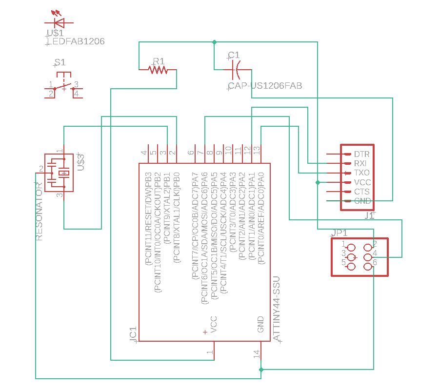
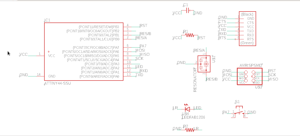
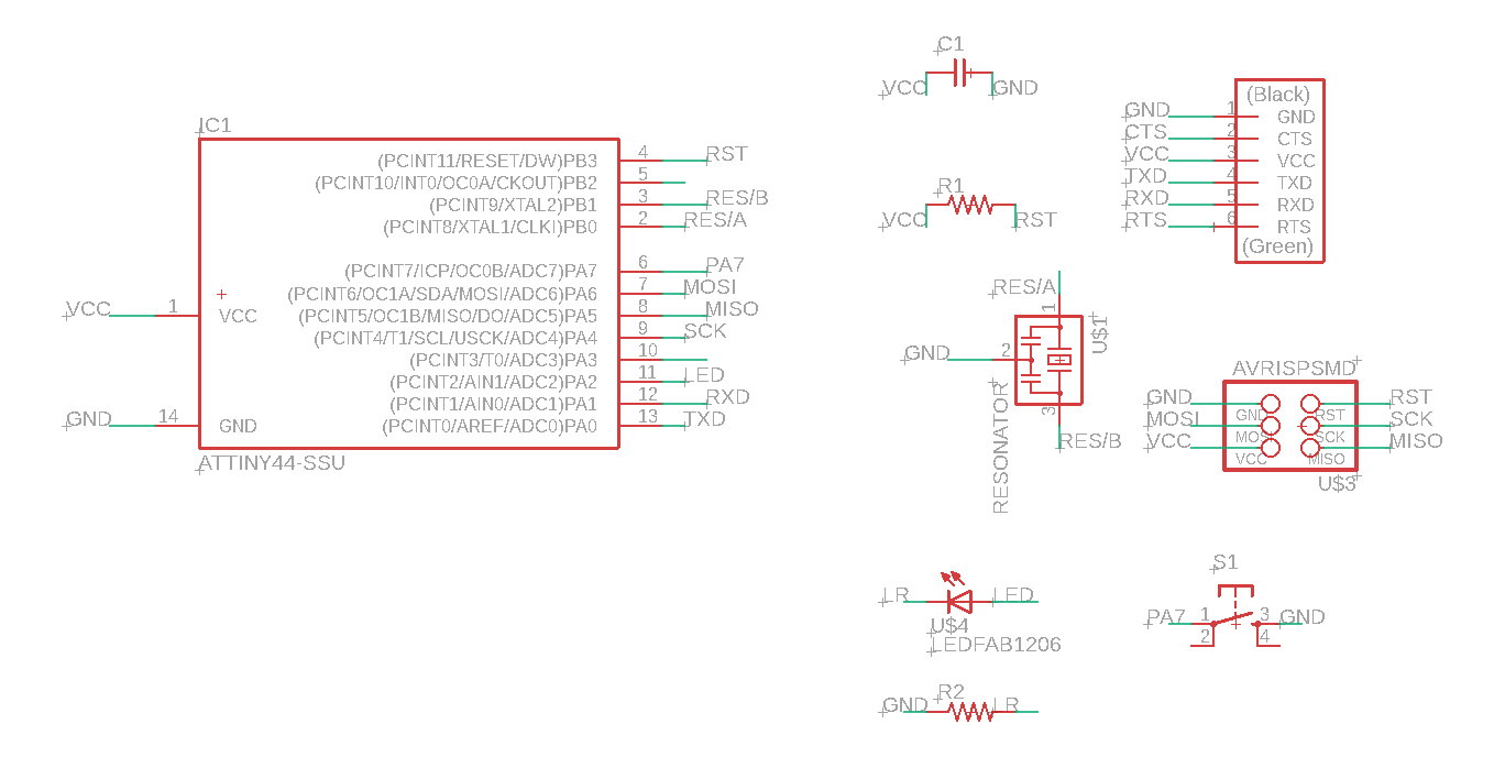
Here is the schematic with everything named.
Stuff the Board
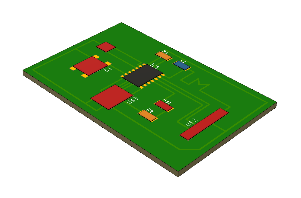
Rendering the board in Fusion 360
Setting up the sync to Fusion 360 to allow 3D modelling of the board.
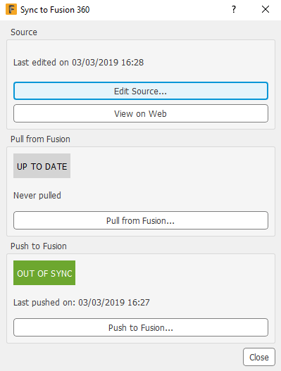
I was slightly dissapointed with the final render if I'm honest - I think I assumed that it would render the components in 3D on the board, rather than just blank rectangles, but I suppose this is the information it gets from Eagle. It is cool to be able to see where everything is and check the size of the board.
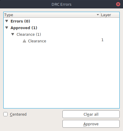
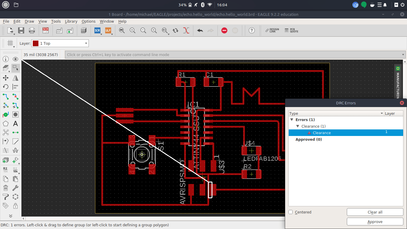
Design rules in Eagle
The design rules tool seems really cool.
 Using mods
The final PNG to send to mods:
Obstacles
Problem 1
Downloads
Eagle Files
Schematic: echo.hello_world.michael.sch (<70KB)
Board: echo.hello_world.michael.brd (<45KB)
References
Online
- Basic Electrical and Electronic Symbols [Accessed 02 Mar. 2019].