Week 10: moulding and Casting
2019.03.20
Individual Assignments:
- Design a 3D mould around the stock and tooling that you'll be using, machine it, and use it to cast parts. Incomplete
Group Assignments:
- Review the safety data sheets for each of your moulding and casting materials, then make and compare test casts with each of them. Incomplete
Week 10 Contents:
Nomenclature
What do we call things?
Rightly or wrongly, when learning new fields I like to know the words that are used. The closest I have come to casting in the past is jelly moulds (before I became vegetarian).
The part that is produced can also be called the casting.
A bivalve mould is a two part mould with each mould casting half the item.
An articulated mould is a multi-part mould.
A mould might be coated with release agent before casting, so that the part can be easily removed.
We will be using the MDX-50 to mill hard wax (the blue stuff we used as a sacrificial layer for milling the boards). This wax mould will then be used to create a silicon mould that we use to cast the actual part. Therefore we are actually creating at least two moulds. The first mould is a mould for the mould. The part will come out of the second mould.
Mould A: Concrete Cable Holder
Fusion 360 Modeling
To start this week I wanted to make something useful. I started off drawing a cable holder for my desk (especially useful for a programmer cable...). The idea is that I'm going to draw the cable holder as a body, then draw a box around the outside of the model to create the mirror (the mould) then one more time to make the mould of the mould... I have no idea if it's going to work, but Fab Academy is teaching me to go for it and see what happens.
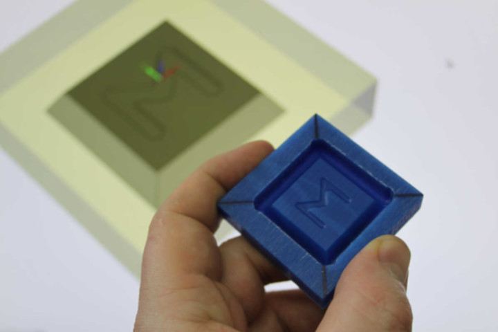
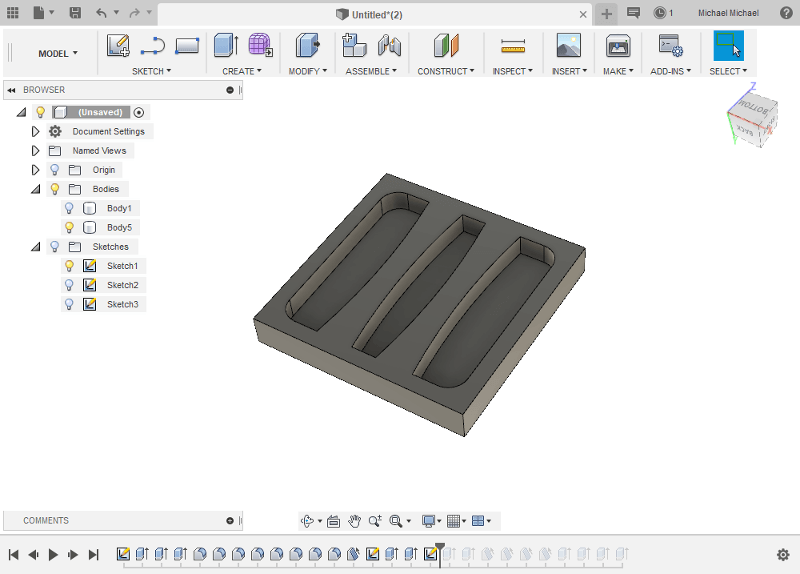
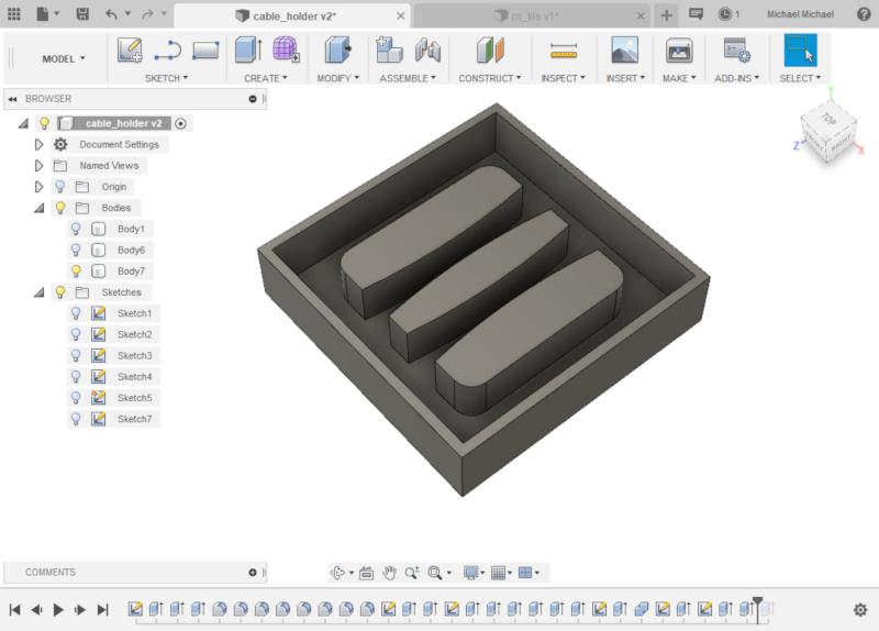
This is the initial sketch. I made the square 60mm x 60mm, the construction lines to divide the x axis of the shape into thirds are 20mm apart. Then the construction lines for the arcs are 6mm either side of the thirds dividers. The arc bends to 2.25mm at its widest point, so the gap for the cable will be 7.5mm.

Next I extruded the whole square down and everything but the cable channels up. I added fillets to the internal corners of the cable channels:
Cast Object View
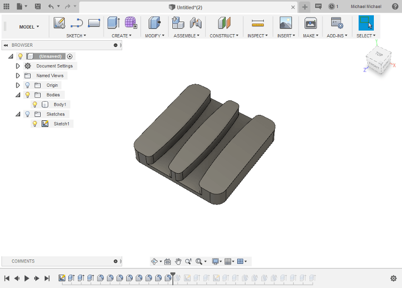
I flipped the design just to see what the final cast object will look like in use. The top of the cable holder will be self-levelled by the pour of the concrete or resin. For this first mould I'm trying not to make it too difficult for myself.
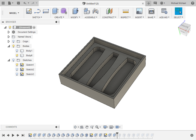
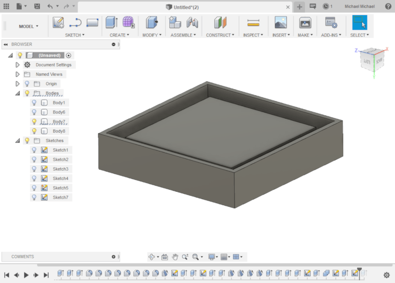
With the design flipped back upside down, I drew this box around the whole model. I thought originally I would cut the original out of the box, but I think I am going to have to extrude the cable channel dividers.
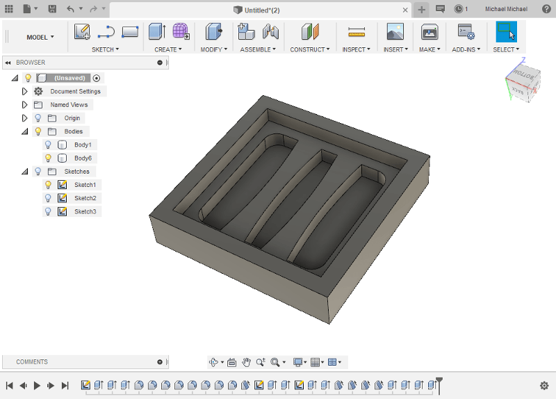
It's very hard to tell, but I have added a 1 degree draft to the sides. This shape would create the casting I need, but not the top of the cable holder, so I needed to create walls to encase the top.
The walls are too thin, but the negative space in this model would produce the cable holder, so I'm on the right track.
Mould View
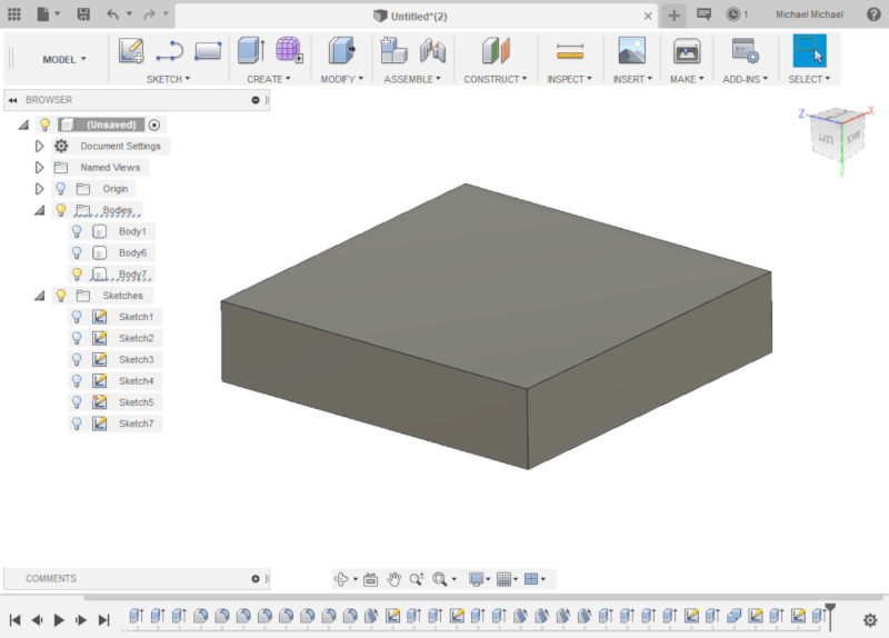
For the next step I thickened the walls of the mould. Now I have the mould as a model. I am going to draw a 3D box around it and cut the mould shape out of it and... fingers crossed... it will work.
Final mould tool
After drawing the box I used a Modify > Combine > Cut operation with the box as the target and the previous body as the tool. This created a new body which is almost right, but needs a base.
I span the design upside down and extruded the walls 3mm.
I drew a 3mm rectangle on one of the sides of the newly extruded walls, then extruded it across the base with a join operation.
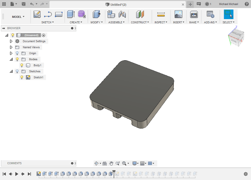
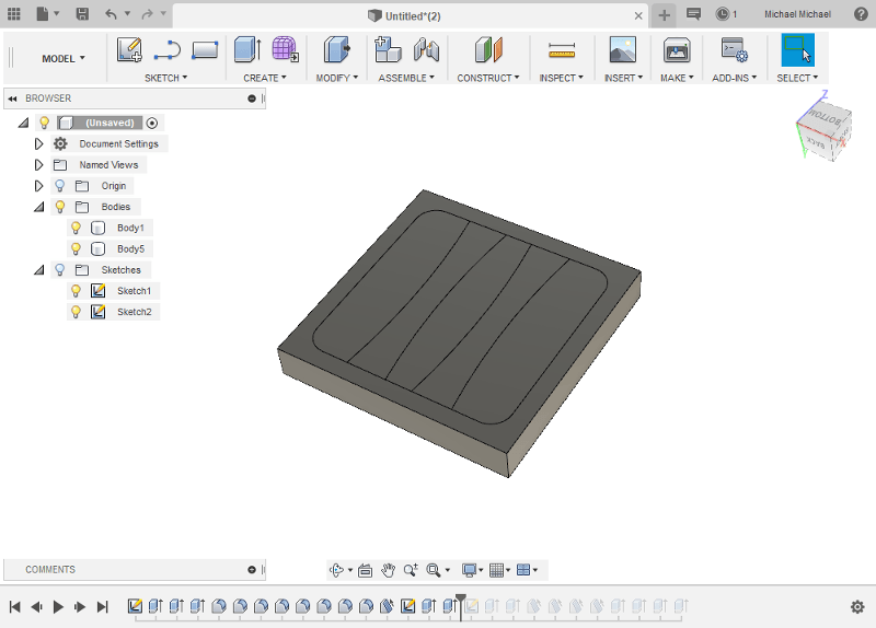
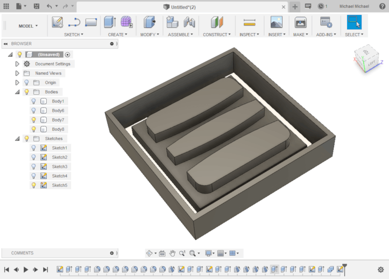
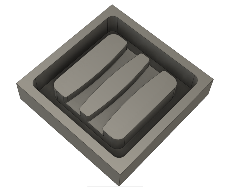
The design flipped back right side up, I extruded the square around the channels down back to the base.
Then I pulled the shapes between the dividers up.

I then filleted the corners of the channels and the outside edges.
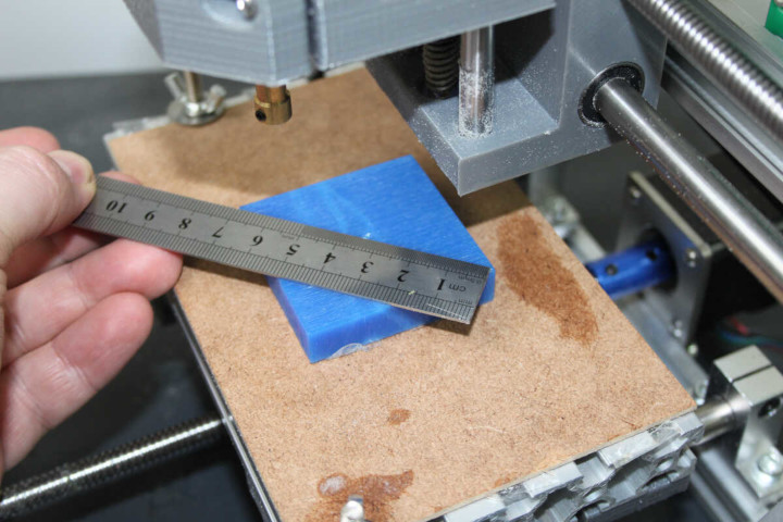
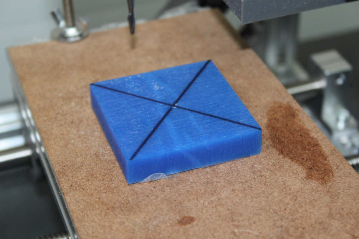
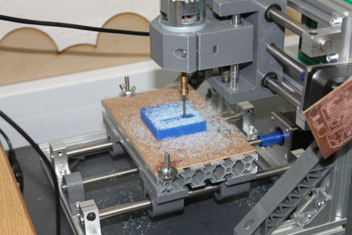
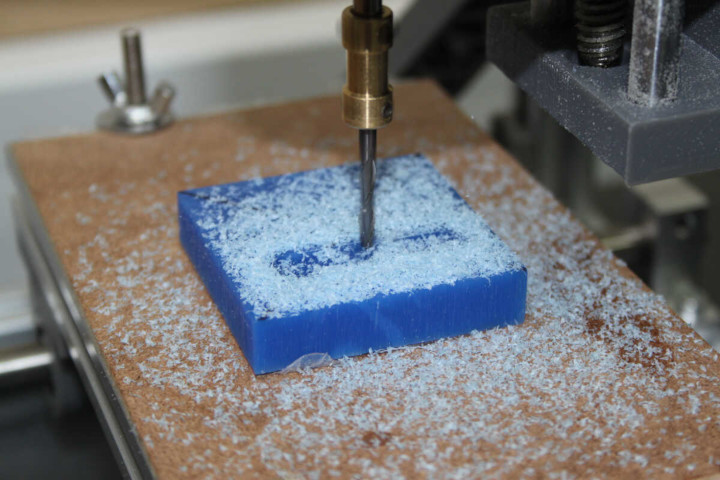
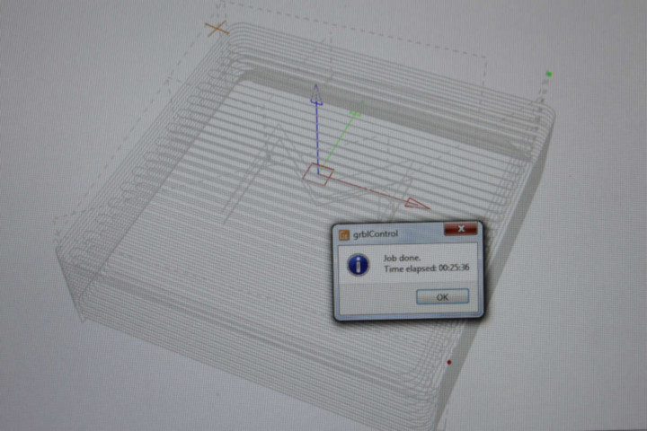
Milling the mould
With the MDX-50
The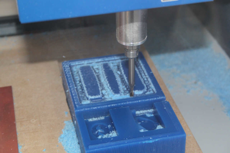
Mould B: Food Safe Small Wax Cut E Tile
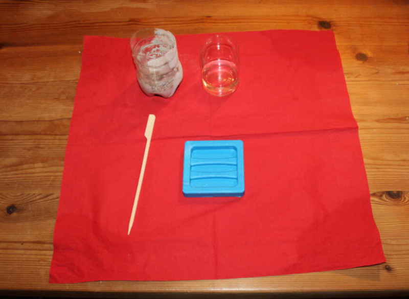
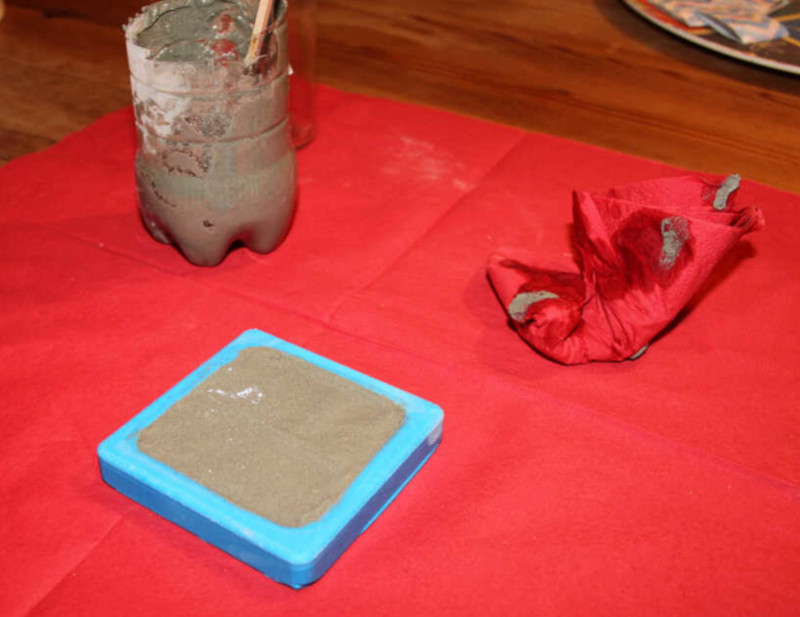
Mixing and filling the mould
The casting material is called Polycraft Food Grade Silicone Rubber from MB Fibreglass in Belfast. The kit consists of 1KG of white(ish) base and 100g of blue catalyst. The material cures blue. The mix ratio is 10:1 and the reported properties are:
| Polymerisation: | Addition |
| Cured Colour: | Blue |
| Cure Time (25C): | 16 Hours |
| Shore A Hardness: | 59 |
| Mixed Viscousity: | 900-1300 |
| Tensile Strength (psi): | 650 |
| Tear Strength (Die B): | 90 |
| Linear Shrinkage: | NIL |