Week 3: Computer-Aided Design
2019.01.30
Individual Assignments:
- Model a possible final project and display it on your website. Complete
Week 3 Contents:
- What I learned this week:
- Model of final project
- Downloads
- References
Introduction
Computer-Aided Design
I am going to use 2 different 2D packages (Illustrator and Inkscape) and 3 different 3D packages (Solidworks, Fusion360 and FreeCAD). I am going to create dice in each package to evaluate which one I like to work with and then create the final project modelling with that package.
Adobe Illustrator
Version: CC 2019
I started this week with the 2D vector drawing tool Adobe Illustrator.
Illustrator uses a path-based system with anchor points to create vector shapes. Once the shape is drawn, the individual anchor points can be manipulated by selecting them with the 'Direct Selection' tool (A). The points show up as filled blue when selected or blue outline and white fill when deselected. New anchor points can be added to change the vector shapes with straight paths, but anchor 'handles' can also be manipulated with various tools to create Bezier curves between anchor points.
The vector shapes can have a stroke (outline) applied - this can be specified in many different measurement systems e.g. mm, points, etc. I found working in millimetres the most intuitive. To 'colour in' a vecotr shape you need to specify a fill colour. Both the stroke and the fill can be gradients or solid fill. The colours can be specified in CMYK, decimal RGB or hex coded RGB or other colour options like Pantone swatches.
The tool I found the most useful is the 'Shape Builder' tool (M). This tool allows you to join paths together to form larger shapes from multiple shapes.
I opened the progrom, created a new document and set the dimensions to an A4 page.
Illustrator Die
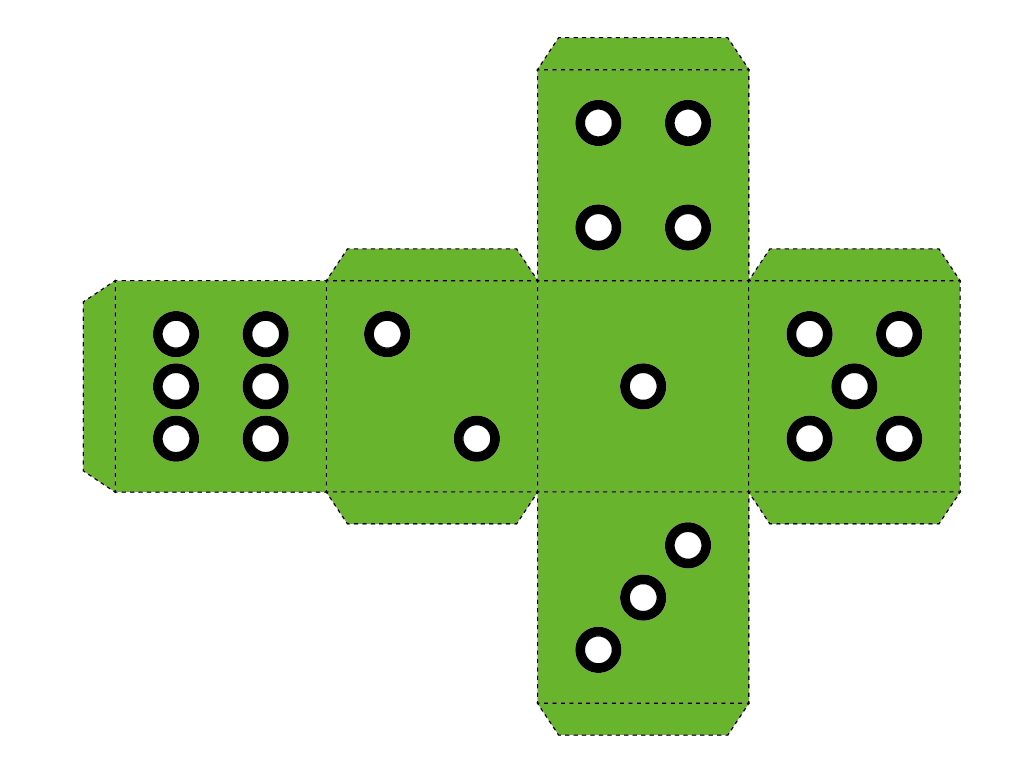
To make a die in Illustrator I first laid out the net. I used the transform menu and chose the move tool to make precise movements to the shapes.
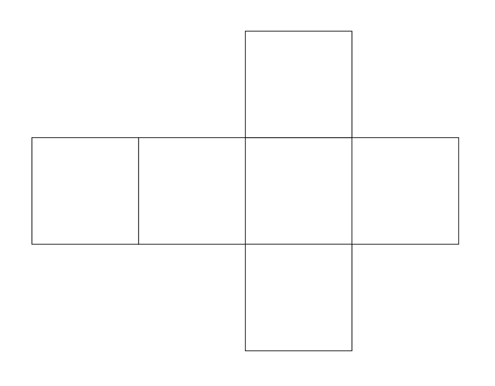
I then added some tabs to the squares that form my boxes.
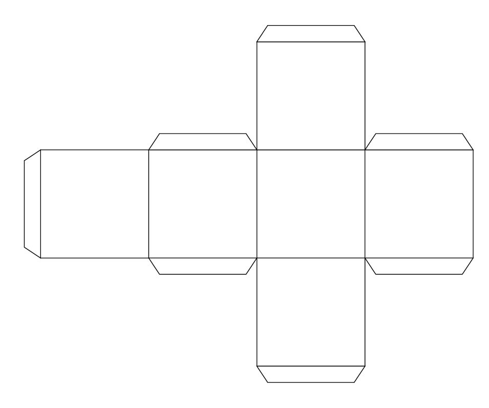
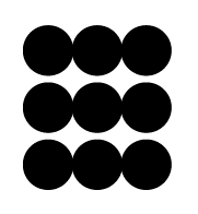
I drew nine pips and copied them on to each box, deleting them to make the dice shapes.
Here's the layout drawn with all the pips in place.
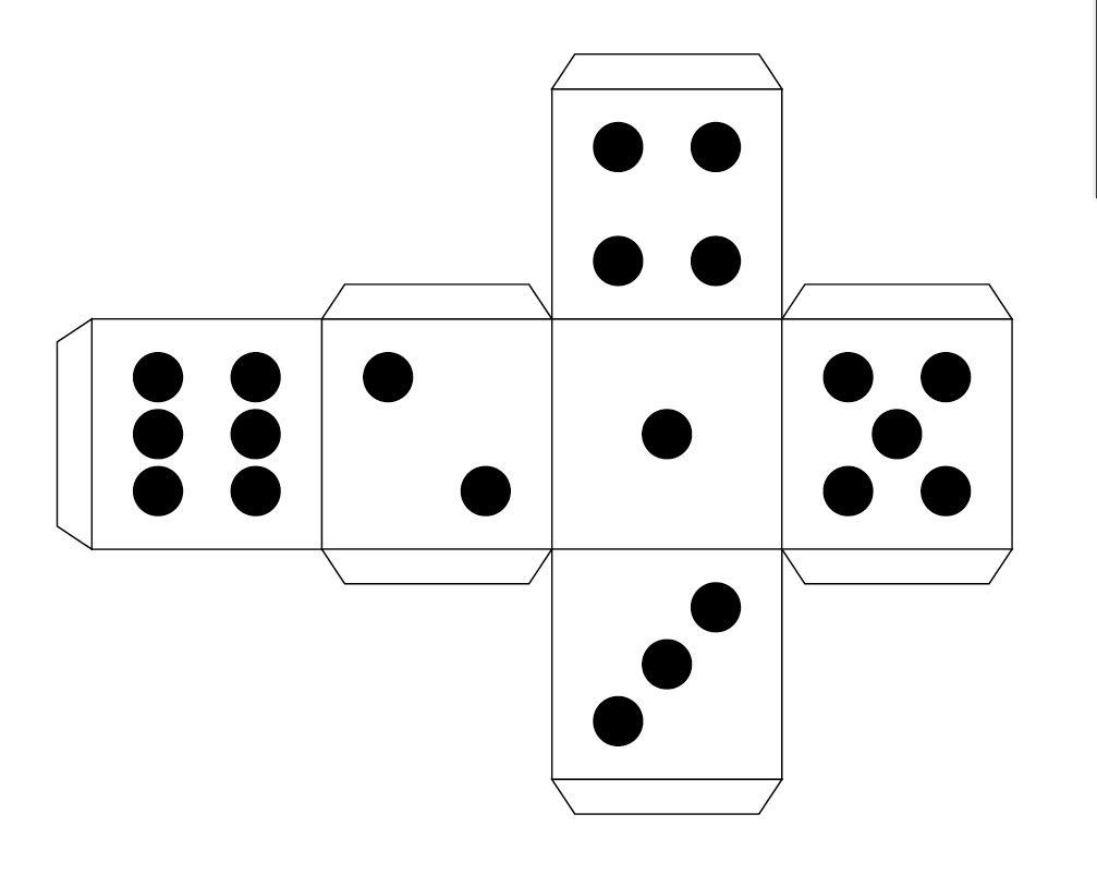
The green net is the final one:
An attempt at 2D modelling an idea for my fianl project.
I think my final project will be very board-based, so am going to consider the rocket, parachute and casing for the CAD this week.
Inkscape
Version: 0.92.3-1
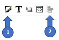
I followed an Inkscape tutorial. First of all, from the end of the main toolbar I opened the ‘Fill and Stroke’ panel [1] and the ‘Align and Distribute’ panel [2].
I then drew a circle using CTRL to constrain the width/height and SHIFT to draw the circle from the centre out.
After selecting the circle, I then clicked on the lock icon between the width and height fields constraining them to each other.

I then duplicated the circle, reduced the copy in size to 175 px and cut out the smaller circle from the centre of the larger one by aligning them horizontally and vertically, selecting them both and choosing Path > Difference.

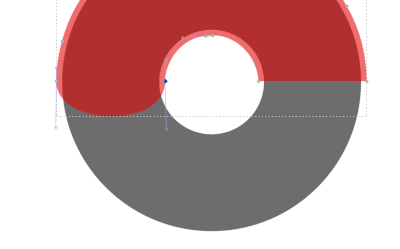
I then changed the opacity of the resulting donut to ~50% and duplicated it on top of itself. Using the Path > Outset command, I then offset one donut from the other.

CTRL + scroll-wheel zooms in and out. I zoomed in and drew a rectangle over the bottom half of the drawing, I then used difference again to cut away half of the outset donut.
Using the ‘Edit Path by Nodes’ tool (F2) I rounded off one side of the half-donut.
I then added extra nodes using the plus button on the node tool contextual toolbar and dragged the centre node up. I repeated this on the other side. Holding CTRL and clicking on the nodes allowed me to round the corners by dragging the node handles.

I then changed the colours of the donut.

Next, I drew three circles, slightly overlapping with the side ones smaller than the larger centre one. Once they were looking like a bite pattern I used Path > Union to make the following shape:


I positioned them over the donut and used a bite shape to take a section out of each layer of the donut (chocolate, highlight and donut). This created a realistic looking bite mark.


To create the sugar sprinkles I duplicated a small rounded rectangle with the patterning tool. I then changed the colour of the chocolate to be lighter. Here's the final donut.
 Here's a donut I drew in Illustrator for comparison. I actually found the Inkscape process more logical, which suprised me. I was expecting Illustrator to win hands down, but I think Inkscape is a fantastic piece of software and some of the interface elements are easier to use. I really like the 'click once for scale, click twice for rotation' feature on the vector shapes.

Dassualt Systèmes SolidWorks
Version: 2018 SP4
SolidWorks offers a student version and it was really easy to get installed and get a year long licence activated.

As with the other programs I am going to try to make a die to get a feel for the program. On the sketch tab I chose a two-point square and chose the plane in which to draw it. I then drew the square and dimensioned it by clicking on an edge and right-clicking for the ‘smart dimension’ tool.
I then switched to the ‘features’ tab and used [Boss-Extrude] to pull up the sketch into a cube.
At this point I began to wrestle with the user interface a little. I wanted to draw a circle (pip) on one of the sides of the dice. Orientating the cube with a right-click was easy.
I then clicked on ‘sketch’ and chose the side I wanted to draw on. I then discovered centrelines under the line tool and drew some lines from corner to corner.
I then drew a circle and changed the radius to 5mm.
Using the centrelines tool I aligned and then pushed the circle back into the cube. Once this was done I made a sketch and drew the pips on each side of the dice.
I selected and filleted the edges of the cube, setting the radius of the fillet to 2mm.
I then added a candy apple red appearance from the plastics appearance section.
Finally I used a render preview to get this image:
Solidworks First Impressions
My first impressions of SolidWorks compared to the other 3D packages is that the interface was difficult for me to access – the tools and features seem to be divided into categories that are not intuitive (what is DimXpert for example?). Obviously a lot of this is because of my own lack of knowledge of the package and with continued use these features would become clearer.
FreeCAD
Version: 0.18
I downloaded the 64-bit version of FreeCAD for Windows. It crashed the first time I ran it, which didn't fill me with confidence, but I actually really liked it once it got running. I followed a tutorial from Peter Phelps on Youtube to make a die.
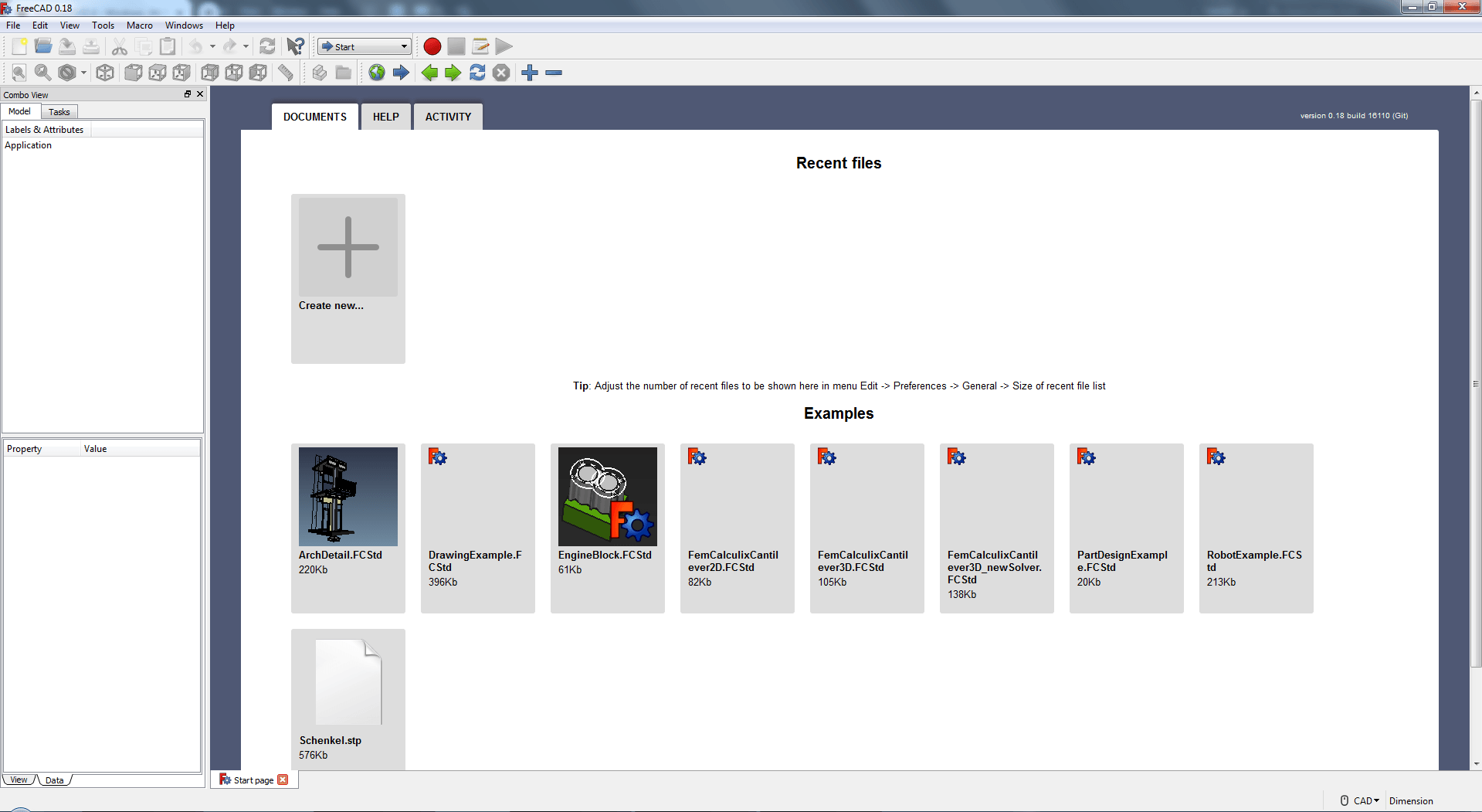
I ran FreeCAD and created a new project
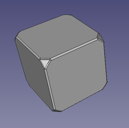
I then selected the ‘Part’ workbench and created a solid cube.
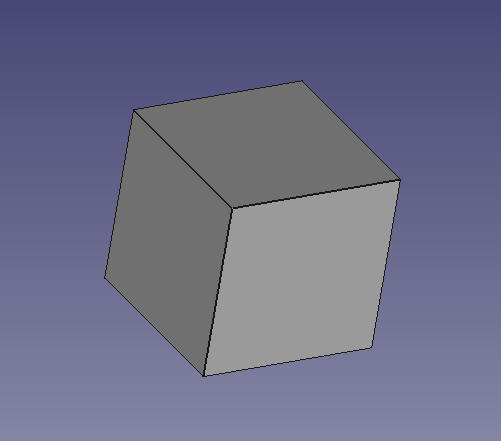
Holding the scrollwheel and right-dragging gives free orbit behaviour.
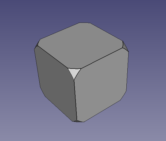
I selected the cube in the organisational list. This shows the properties for the object. I changed the positioning to -25mm (half of the 50mm size of the cube) on each of the X, Y and Z axis which centred the object on the origin.
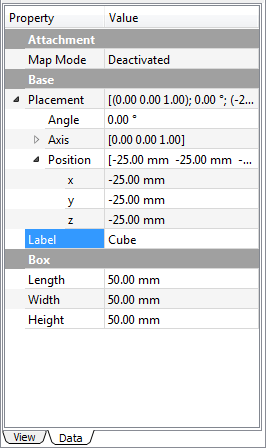
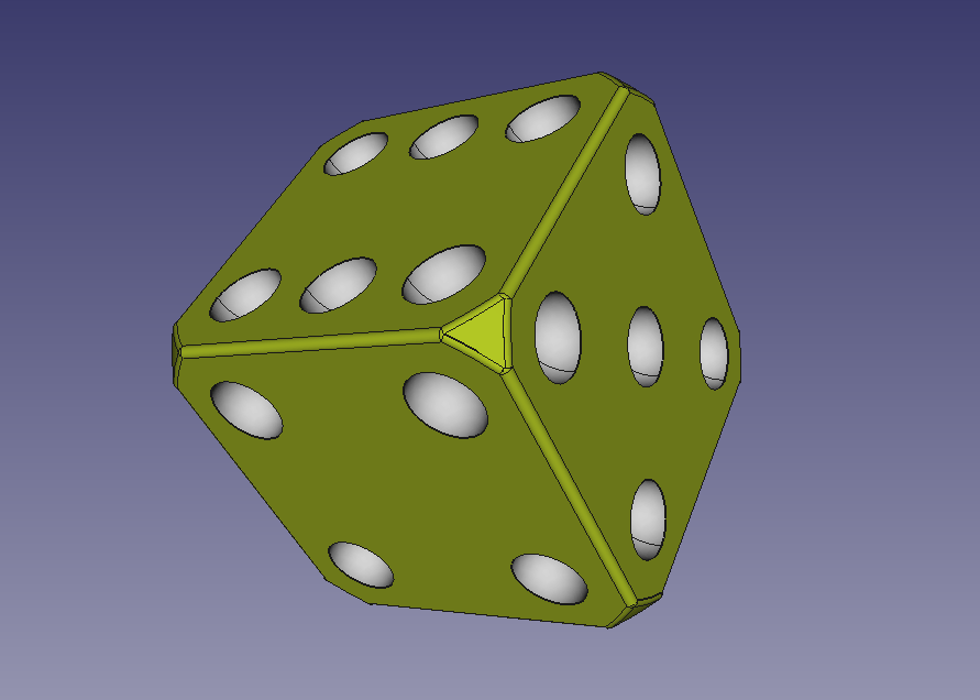
I then made a sphere and positioned it inside the cube, adjusting the sphere to fit so that only the very tips of the cube were pointing out.
I did this by changing the radius of the sphere in the property box.
I resized the sphere to the size I needed, then selected both of the shapes in the organisation list ([CTRL]+Click) and made an intersection of the two shapes using the ‘Common’ button.
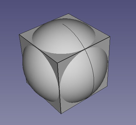
Selecting ‘Common’ in the organisational list I then click the ‘Fillet’ tool. This shows a list of edges. I selected all using the [All] button and applied a constant radius of 1mm.
I then created a 10mm sphere and positioned it at -25mm on the Z axis to make it stick out of the top a little. This sphere is going to carve the pips. I then copy and paste it (just click on the sphere in the list and [CTRL]+[C] before pasting). Then I am going to reposition the pip using the X, Y and Z axis like before.
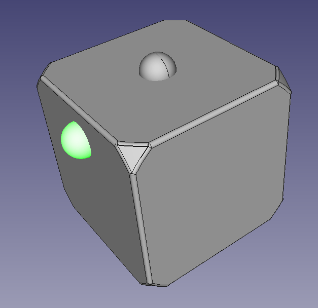
I continued until I had 21 spheres laid out as all the dice pips.
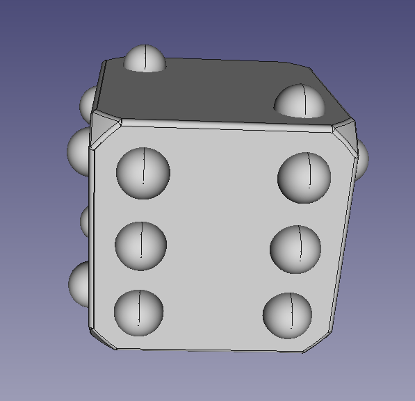
I then selected all the spheres in the list and clicked on the ‘Fusion’ button to make a union of all the shapes. I then selected the cube (Fillet) and the spheres (Fusion) and made a cut.
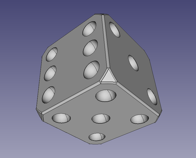
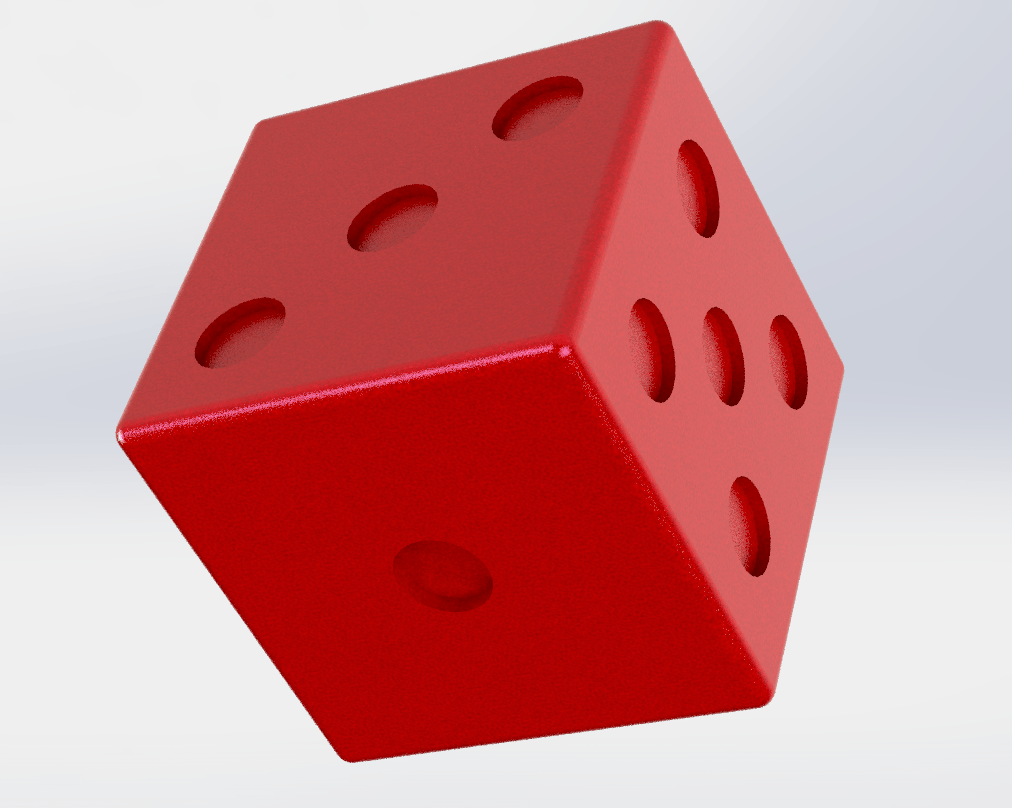
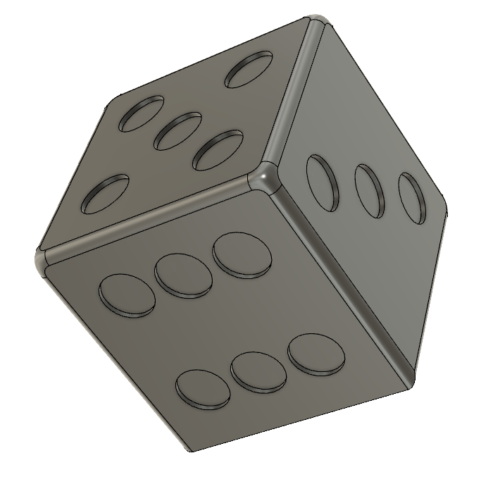
I stepped back and gave a colour to the die (Fillet) and the pips (Fusion) so that when the cut is made it gives the two colour effect.
I then tried to render the die. The povRAY program gave me errors relating to “I/O Permissions”. I discovered on their website that by default writing to file locations is not permitted. I changed the options in povRAY to allow me to write out. Then I added the ‘view’ of the 3D model to the PovProject and rendered the image:
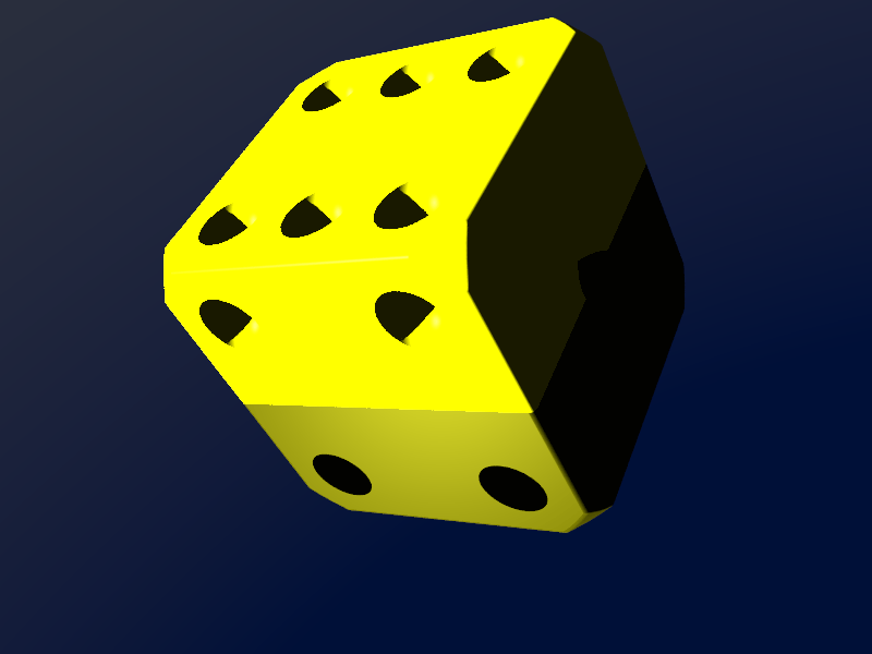
Not quite the result I was looking for, but at least I got something out of the rendering program. I am going to set a time limit of 30 minutes to figure this out, if I can’t get the render better than this, I will have to move on.
Not a fantastic render! I don't know what I'm doing wrong, the example renders from povRAY are absolutely beautiful.
Autodesk Fusion 360
Version: v2.0.5119
Fusion is an entirely new package to me, I have very limited experience of 3D modelling so I am going to concentrate the bulk of my efforts on learning some basic 3D CAD. I have installed Fusion 360 on my desktop PC (Win 10), but there is no version for Ubuntu unfortunately.
Fusion 360 Tutorial Outcomes
I followed a tutorial on Fusion 360, to construct a conduit. First I started with a sketch, this was then extruded in to a body. Then I filleted the outsides of the shape. Next I added a pipe section and cut out the centre all the way into the body of the main shape. I then added an external body with a screw thread. Finally I modeled a lid for the conduit. The timeline video is shown below:
Fusion Die
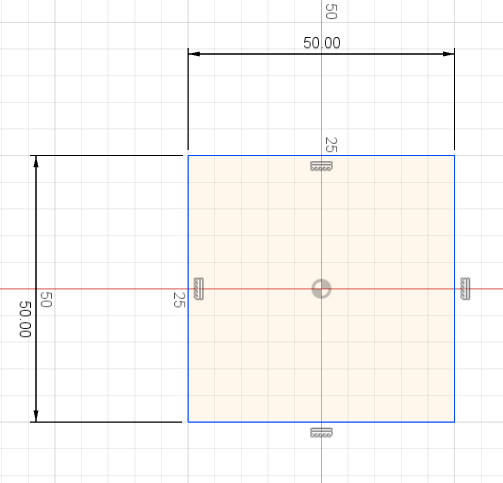
I clicked this button on the Sketch panel to open a new sketch.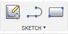 I chose the plane in which I wanted to draw.
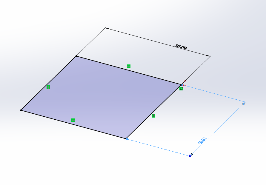
I selected the two-point rectangle and dimensioned a square at 50mm x 50mm.
I chose the plane in which I wanted to draw.
I selected the two-point rectangle and dimensioned a square at 50mm x 50mm.
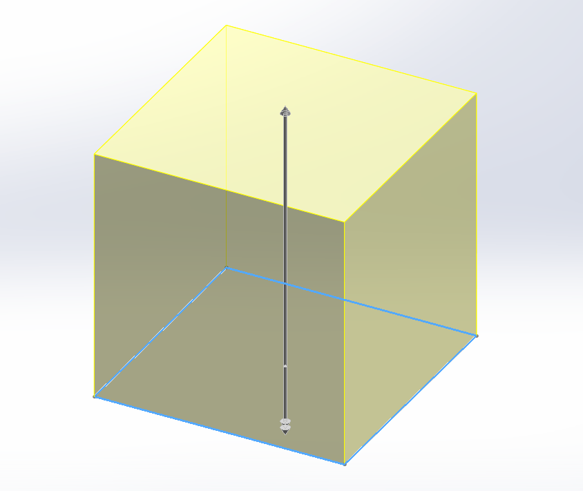
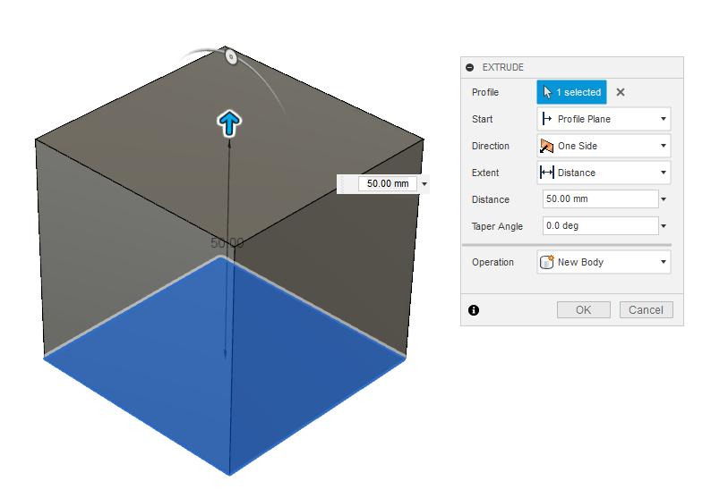
 I then clicked the ‘Extrude’ button on the Create panel and dragged the base plane up to 50mm to create a cube.
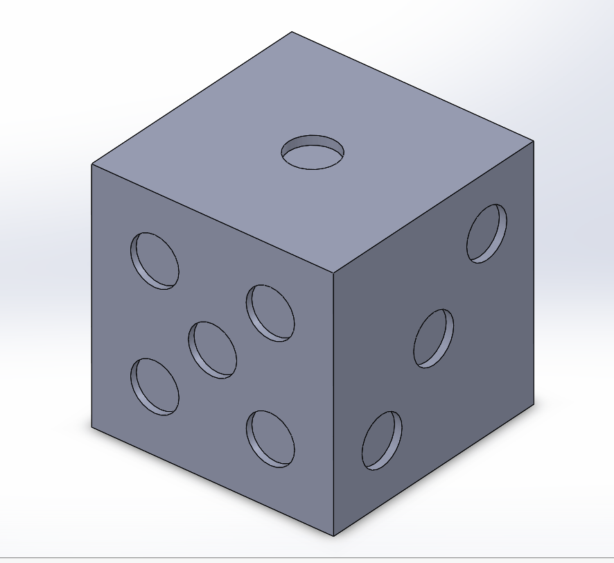
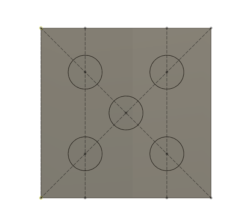
 Using some construction lines I laid out 5 dots on the dice and extruded them -1mm back into the cube.
I continued this around each side until I had a full die.
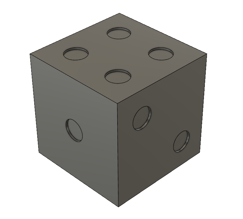
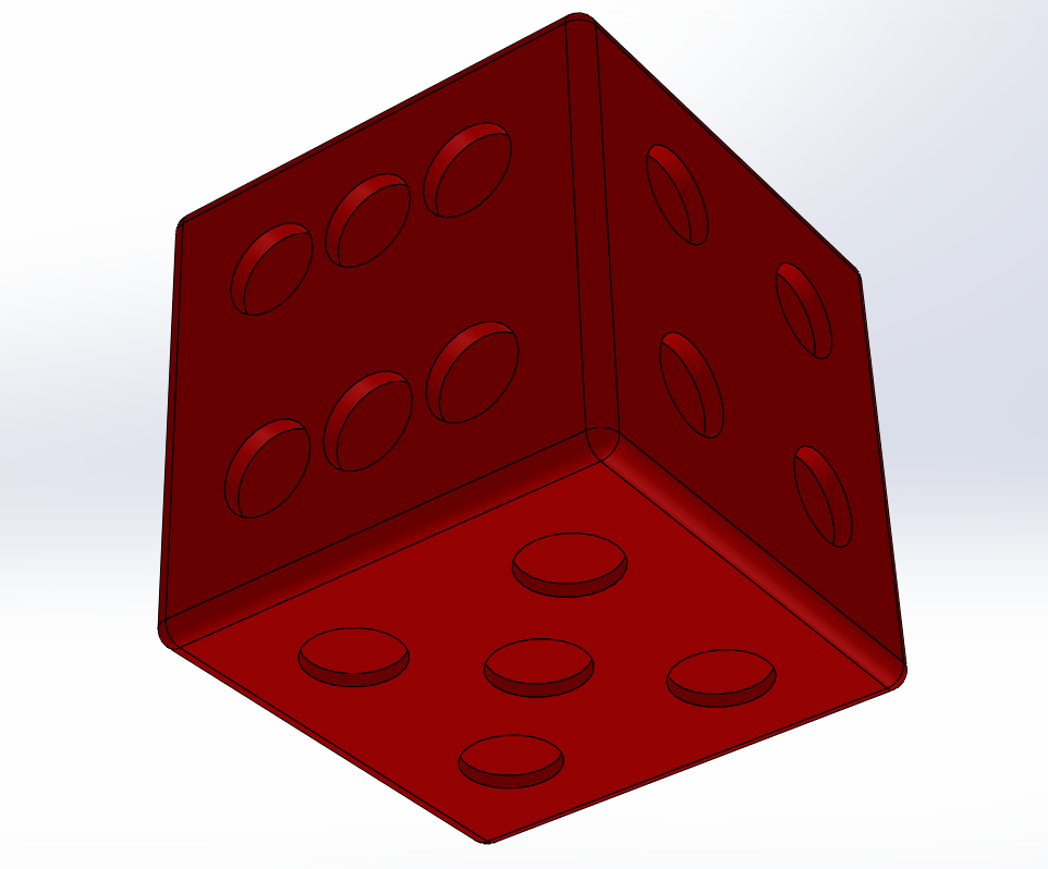
I then filleted the edge of the die with the fillet tool and chose a ‘setback’ corner type.
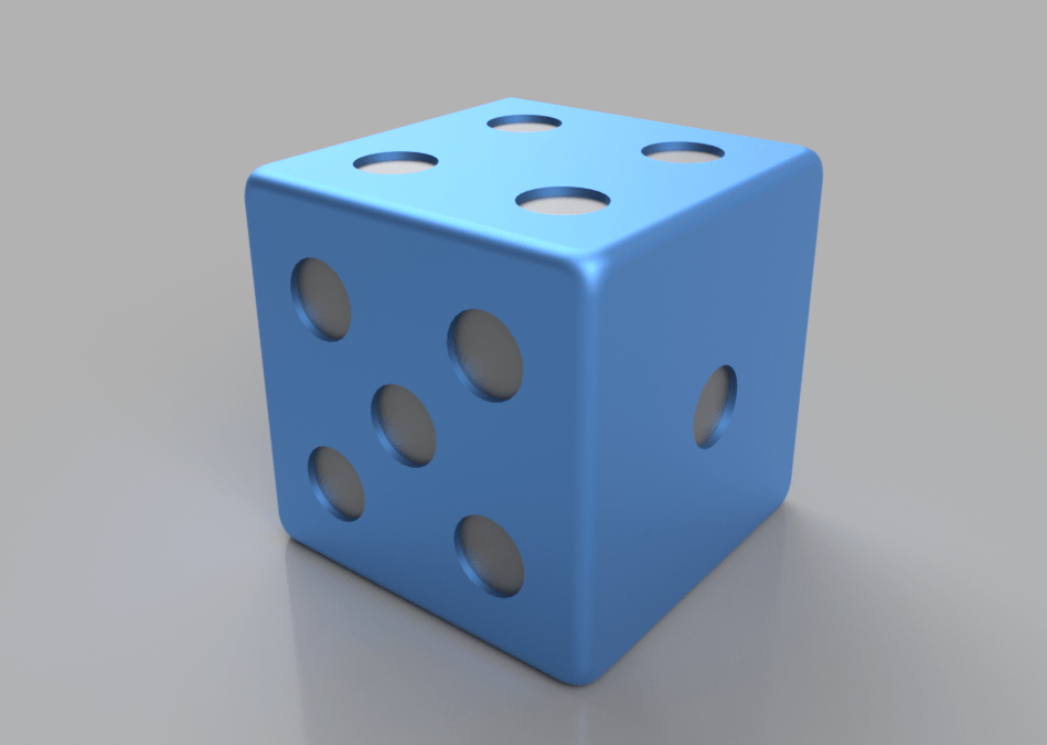
I then added a blue aluminium finish to the main die and a grey aluminium finish to the pips.
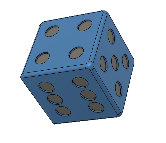
Here is a render of the final item:
Fusion 360 First Impressions
I love the interface. The tools seem laid out where I would be able to find them even without being too experienced with Fusion. I like the mouse gesture interface and the sketching seems much more intuitive to me than with Solidworks. I think Fusion is going to be my package of choice.
I know that Fusion 360 is a lot deeper than I currently understand, but I'm focusing on the 'Model' tool ribbon. The toolbar provides collections of tools divided into: Sketch, Create, Modify, Assemble, Construct, Inspect, Insert, Make, Add-ins and, finally, Select. I am currently mostly using Sketch, Create and Modify tools.

Sketch
One way to start a model is with a sketch. A sketch is a 2D (or in some complex cases, 3D) vector drawing that can be extruded into a 3D body. There are lots of tools under the sketch dropdown, mostly ways of drawing geometric shapes, lines, arcs and then some extended tools for mirroring and patterning shapes. I found this page really helpful.
Create
The 'Create' tool set has a variety of tools for making sketches into 3D shapes by extruding, revolving, sweeping, lofting, etc.
Bodies and Components
Bodies are 'modeling entities used to add or remove geometry to achieve the final shape of your design' (Autodesk, 2019b) and a component is a representation of a finished part, constructed from bodies. The Autodesk help pages suggest that you should create a component first as this will maintain all of the timeline. If you have to convert a body to a component later, you will lose the history of the body.
Fusion is a fanstatic package and the more I use it, the more I love it. I think the user interface is really intuitive with multiple ways of accessing tools. For a program with so many features and tools the graphic user interface is remarkably clean and easy to access. There are lots of different ways to sketch, sculpt and create shapes and bodies, but the workflow I usually follow is to sketch shapes, extrude and then modify. I still need to improve at applying constraints as I often break the integrity of shapes when resizing, moving or changing sketches.
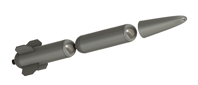
Nosecone Modelling
First steps towards something useful for the final project
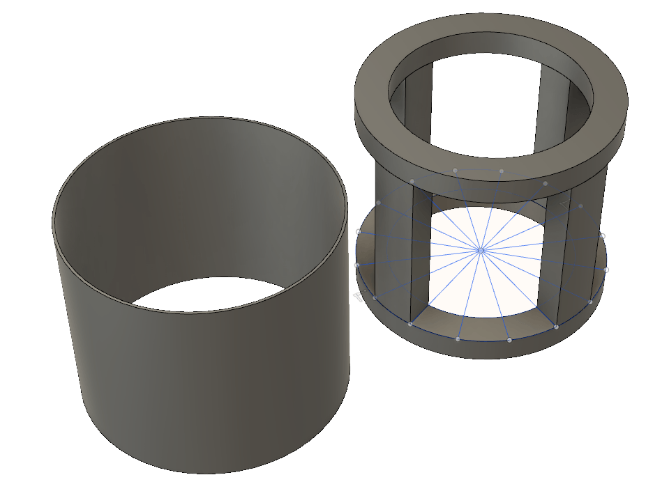
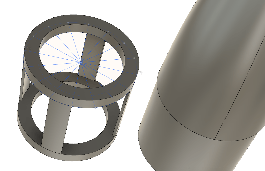
Here is the start of the subframe for the nosecone.
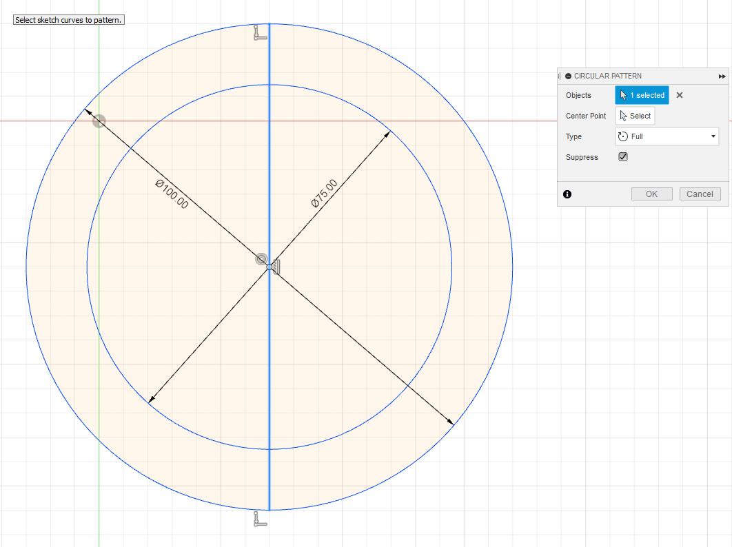
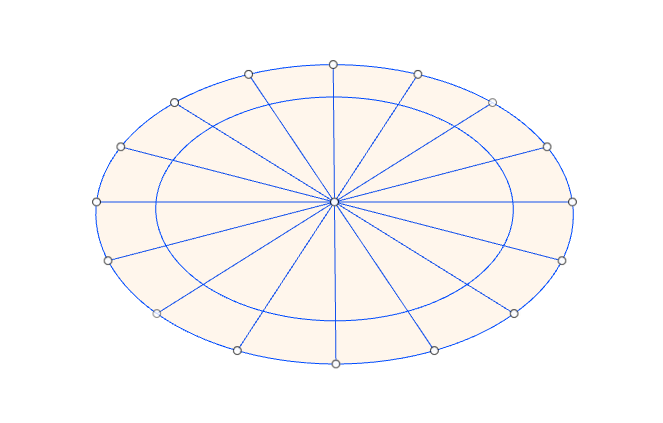
As I progress in using the software I have used some more of the features. In sketching my nosecone, I used the circular pattern tool to divide the ring into sections to extrude.
Extruded struts for the subframe.
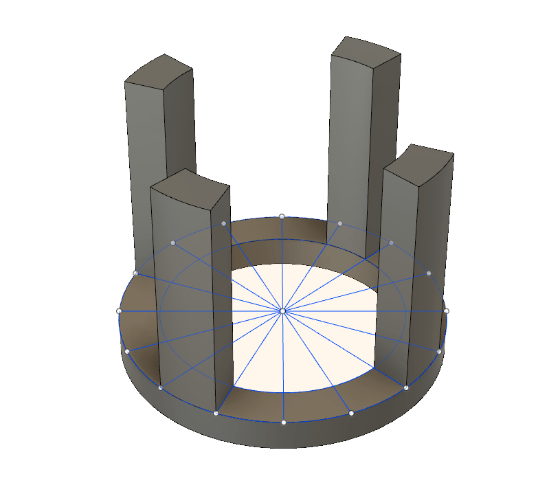
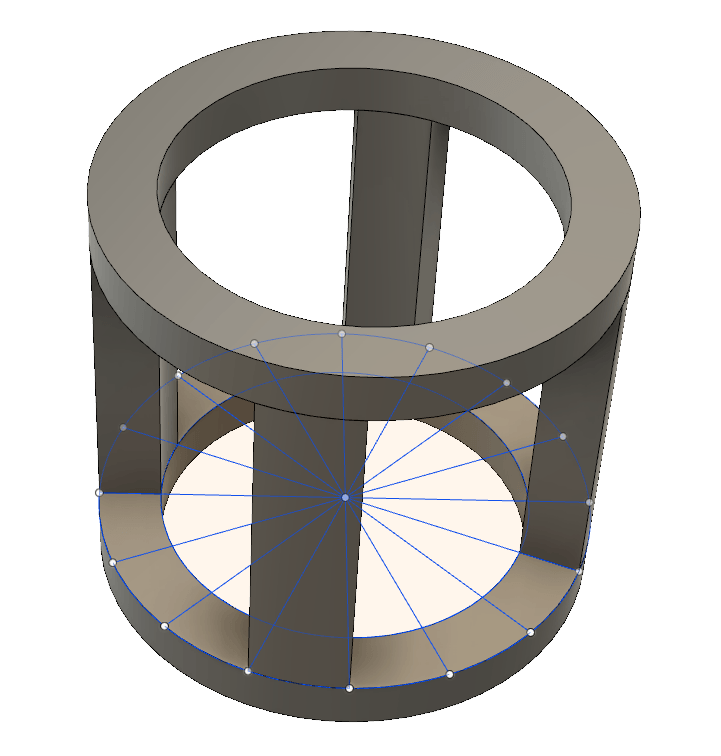
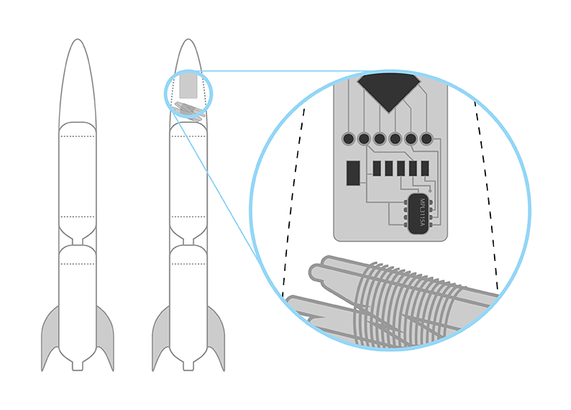
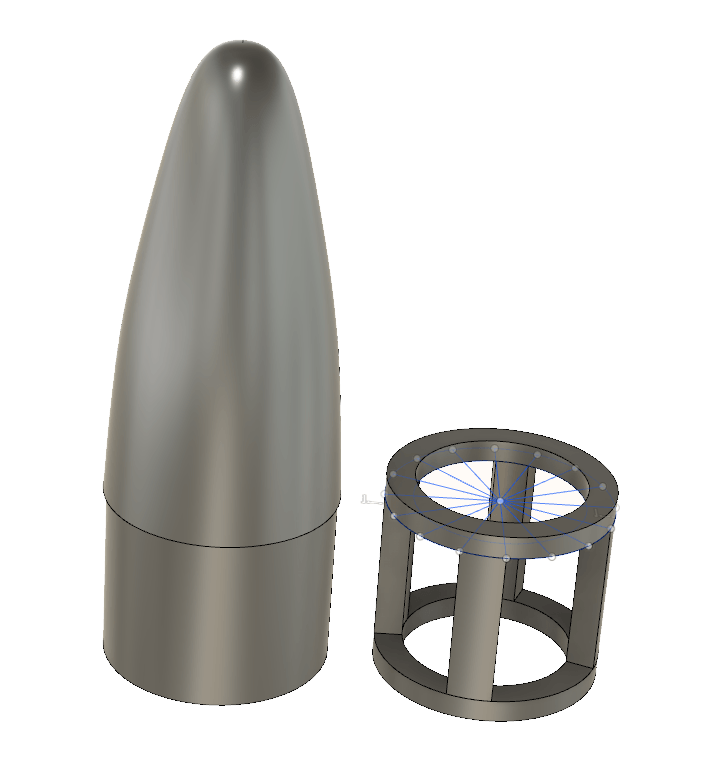
The cylinder is the base of the nosecone. It will hold the electronics. I expect this part to be vacuum formed or carbon fibre. The subframe would be 3D printed and fit snugly inside the cylinder to provide strength and protection to the electronics.
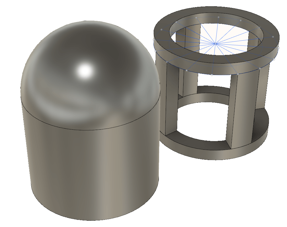
Then I placed a sphere, with the notion of stretching out the nosecone.
The plain sphere I used above could not be moved around, so I used a sculpting method to place a new sphere.
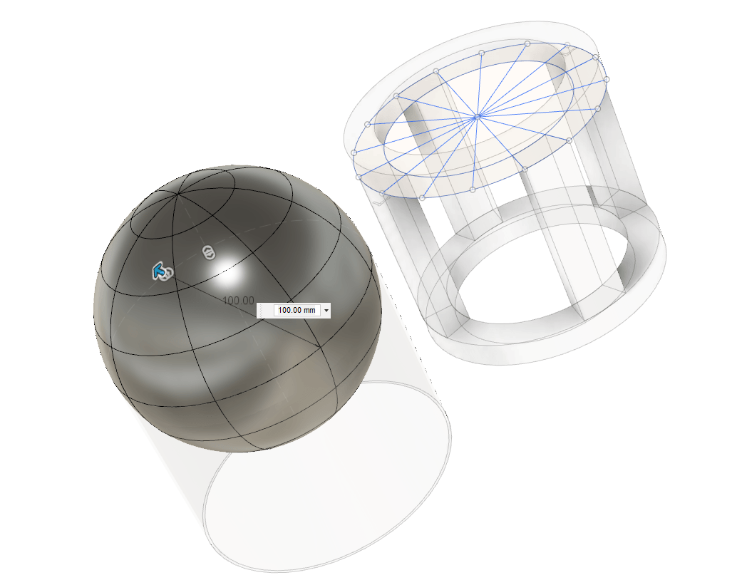
This allowed me to pull the nosecone into shape.
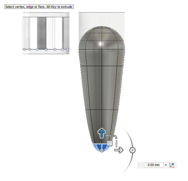
I cut off the bottom of the nosecone and tried to match it to the cylinder - the stretching has moved the shape beyond 100mm, so it doesn't fit exactly. I tried to scale the nosecone by 0.98 to make it fit.
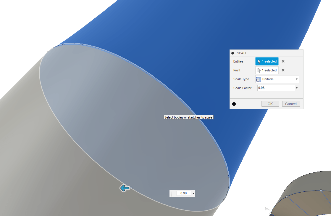
This method didn't really work. I wasn’t happy with the shape and the way it fitted – it didn’t scale from the centre, so the cone was slightly offset from the cylinder. I stepped back along the timeline and reshaped the sphere to a nosecone shape I was happier with.
I then thinned out the subframe struts. I think I will also add holes (like a drilled race car) to remove weight.
The lower cylinder and the subframe will house the control board and the electronics. The cone will house the parachute and release mechanism. These CAD models are almost like preliminary sketches – I will flesh out these designs over the coming weeks.
Conclusions
I love the concept of open source software and I am a Linux user, but for some reason I really liked probably the two most proprietary softwares of all the modelling software I tried this week. I have used Adobe Illustrator for many years and I am very comfortable with it, so this was an obvious choice for 2D modelling. I am lucky enough to get access to it through the University too, but I have heard a lot about Inkscape and wanted to try it out properly having used it years ago in a very early release. I used it for creating (very basic) laser cutter files at BuildBrighton and, to be honest, found it a bit annoying compared to Illustrator, but this week I really changed my mind and actually enjoyed the Inkscape user interface. In terms of 3D I have not done anything more complex than SketchUp and even then I have just used it to create basic shapes. I tried FreeCAD, Solidworks and Fusion360 this week and the user interface of Fusion360 appealed to me immediately. I felt with the time I had available around work this week that it would be useful to focus on one package and Fusion 360 won out very early on. Time will tell if this is the right choice, but I am really enjoying learning about it and the parametric variables feature seems very easy to access. The idea for my final project at the momemt is board-based, which doesn't really lend itself to the week's assignment. I am not really sure what I am going to build above and beyond the board, but obviously I will need to use 2D and 3D modelling throughout the Fab Academy and at the moment my modelling tools of choice are Illustrator and Fusion360.
Downloads
Right-click and choose 'Save Link As...' or similar to download.
Nosecone Files
Nosecone v1: Fusion 360 Archive (121KB)
Test File Downloads
Right-click and choose 'Save Link As...' or similar to download.
Dice Files
Illustrator Green Die: .PDF (58KB)
Solidworks Red Die: ..SLDPRT (145KB)
Solidworks Red Die: .SLDPRT (145KB)
Fusion360 Blue Die: .f3d (129KB)
References
Online
- Autodesk Fusion 360 Help, 2019 [Accessed 04 Mar. 2019].
- Autodesk Fusion 360: Bodies and Components, 2019b [Accessed 04 Mar. 2019].
- Vector Conversions [Accessed 16 Mar. 2019].