Week 4: Computer Controlled Cutting
2019.02.06
Individual Assignments:
- Cut something on the vinyl cutter. Complete
- Design, lasercut, and document a parametric press-fit construction kit, which can be assembled in multiple ways. Complete
Account for the lasercutter kerf. - For extra credit include elements that aren't flat. Complete
Group Assignments:
- Characterize your laser cutter's focus, power, speed, rate, kerf, and joint clearance. Partially Complete
Week 4 Contents:
- What I learned this week:
- Construction chips
- Laser characterisation
- Obstacles and Solutions
- Downloads
- References
Vinyl Cutter
Skull and Crossbones Vinyl Cut Sticker
This week the first thing I tried was a vinyl laptop sticker using the Roland GS-24 cutter in the lab.
Here are the instructions for the Roland CAMM-1 GS-24.
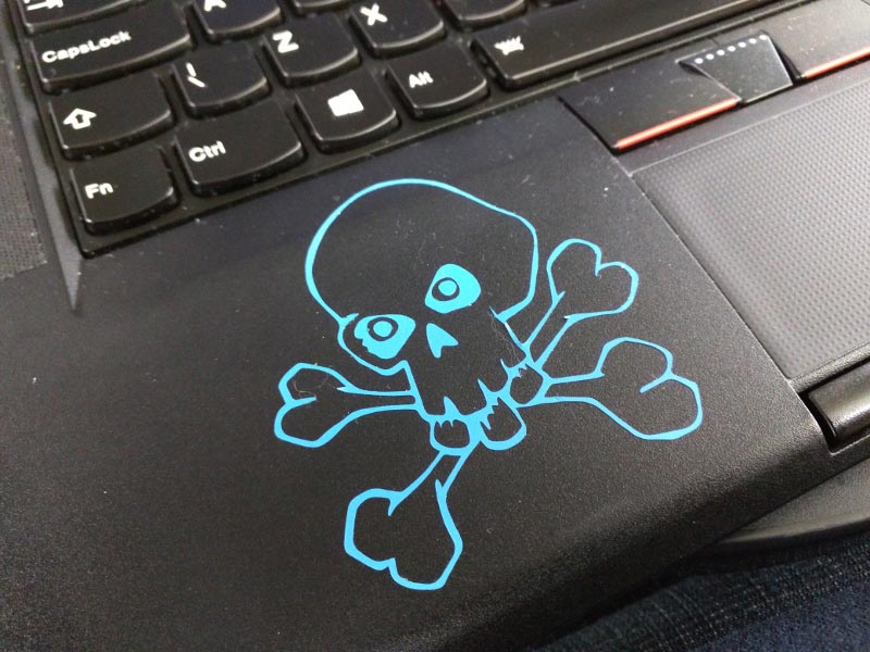
I drew a skull and crossbones cartoon by hand using pencil. I then outlined the drawing using a 0.8 mm graphic marker. I then scanned it using a desktop scanner at 1200 DPI. I opened the resulting TIFF in Adobe Photoshop and ramped the contrast right up, to differentiate really clearly between the pencil, the graphic marker outlines and any marks on the paper. Using Adobe Illustrator I used the 'Image Trace' tool set to 'Sketched Art' converting the drawing to a vector. I then tidied up the vector, removing shapes I didn't need and tweaking the design slightly. This is the final vector that I cut out for my laptop:

The transfer tape ordered for the lab had not arrived by the time I did this first one, so I bodged it with parcel tape. The weeding was quite hard to do as the parcel tape was too sticky and my focus on documentation slipped, so these are the only photos. The skull on blue vinyl sticker:
Liverpool Stickers
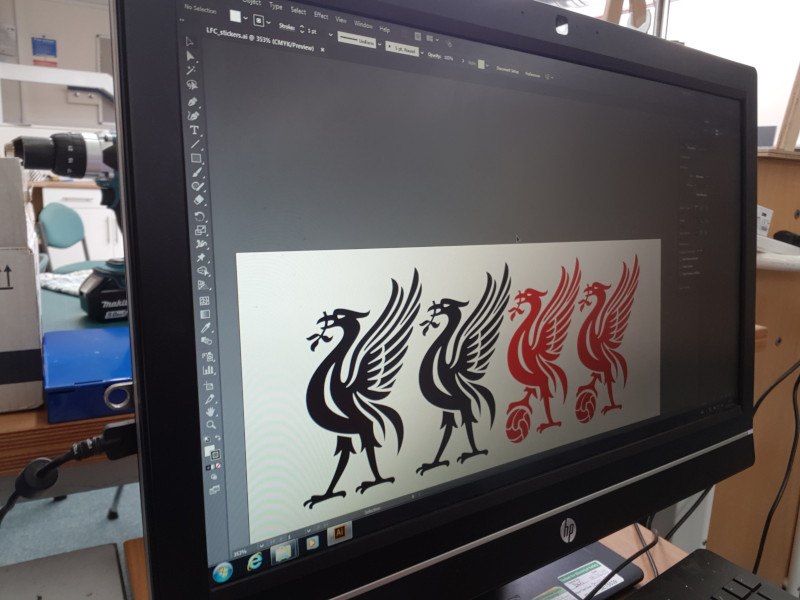
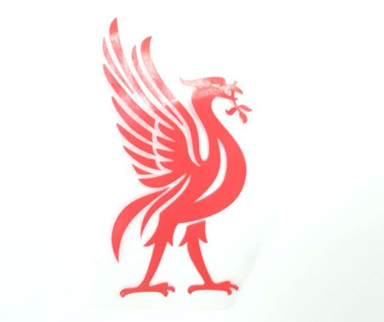
Now I have some transfer tape here is the process in more detail. To load the vinyl I turn on the machine, then choose 'PIECE' from the menu (down, down, enter). This then runs the piece of vinyl through the machine and scans the size (in this case 135mm x 58mm). To make sure the cut fits on the vinyl I created an Illustrator file to those dimensions and sized the Liverbird vectors to fit.
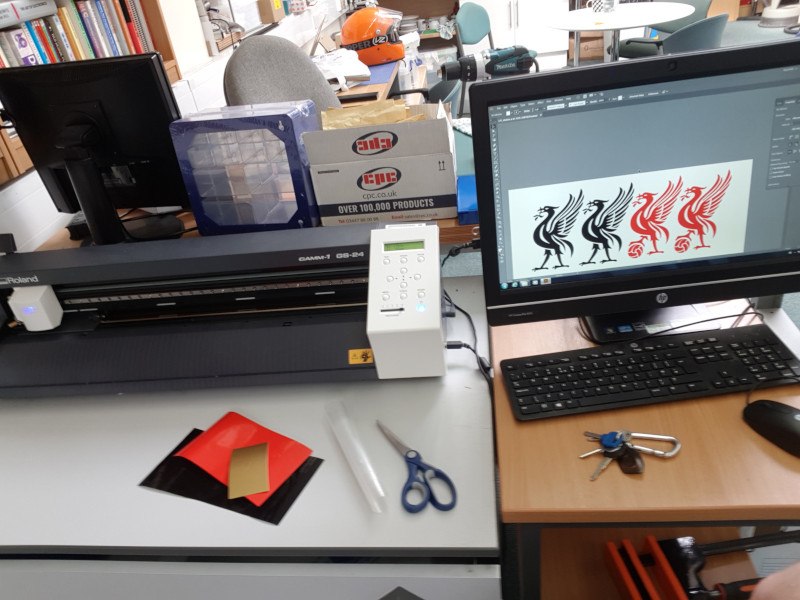
Here is the vinyl cutter with a piece of silver vinyl loaded - the vinyl in front of the machine (gold, red, black) were some of my experimental pieces. The gold was too small to load, the machine wouldn't take it.
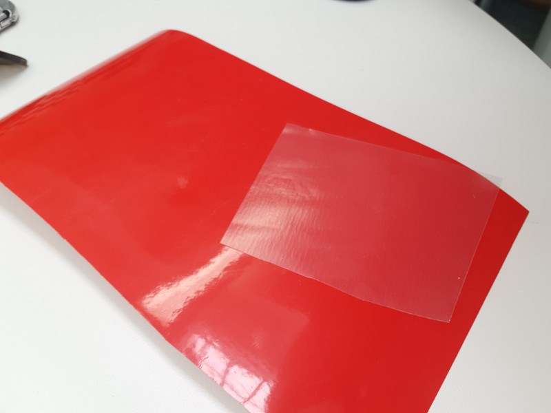
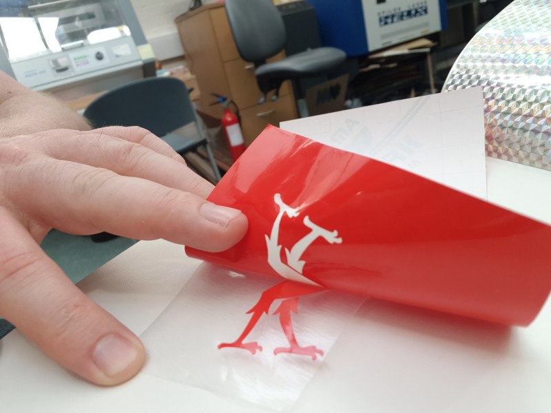
After cutting a test with the silver vinyl I cut a larger Liverbird with the red vinyl. Here is the cut vinyl with a piece of clear transfer tape over the bird. The idea is that the transfer tape will lift only the cut item, leaving the rest behind.
Here I am pulling back the transfer tape and you can see that part of the tail stayed on the backing paper. Using a knife I 'weeded' these parts out, sticking them to the transfer tape.
Here's the Liverbird backwards on the transfer tape - this is sticky side up for both the vinyl and the tape.
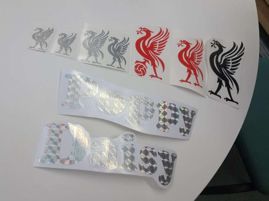
I made a few more Liverbird stickers and some shiny name stickers for my nieces. After doing a few, I found it easier to remove the outside (scrap) vinyl leaving the parts I wanted on the backing tape, then sticking the transfer tape on top for later.
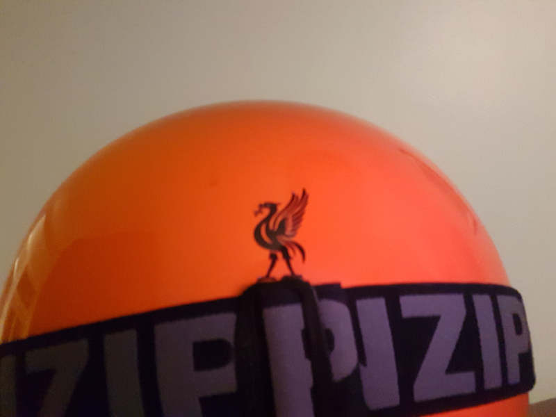
Here's a Liverbird applied to my motorcycle helmet:
Construction Chips
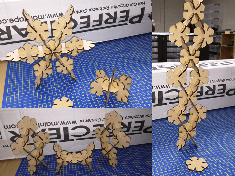
Hexagon chips
The first chips I cut were 6-sided. I liked them, but the 30 degree gaps between the slots made the construction flow in a certain direction - they are great for building the snowflake designs (might make a good present for my mum!), but I wanted a bit more freedom when building. I really like hexagons, so I was a little hasty to base the chips on them, without really considering the ramifications. It was a useful excerise though, especially to practise with Fusion 360. Here's some of the shapes I constructed:
When cutting with a saw it's easy to see and measure the kerf (the portion of material removed by the cutting process), it is the width of the saw blade plus any extra protusion of the saw teeth. On the laser cutter it is much more difficult to measure the kerf as the laser removes a much smaller piece of material as it cuts. This is a blessing in some ways as it makes precision cuts possible, but it also causes 'baggy' joints, slightly wobbly constructions, misfitting parts, etc.
The goal of this week is to create push-fit construction chips that are precise enough to grip each other, but are also easy to push and pull apart. A key step in this process is to determine the kerf of the laser with a particular material, so that precision fitting parts can be produced.
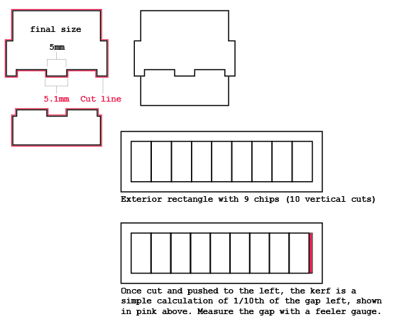
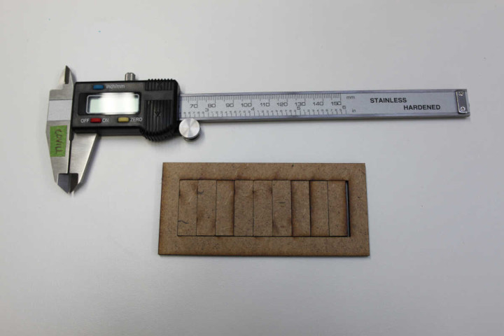
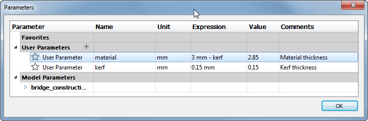
This method produced a kerf measurement of 0.15mm:
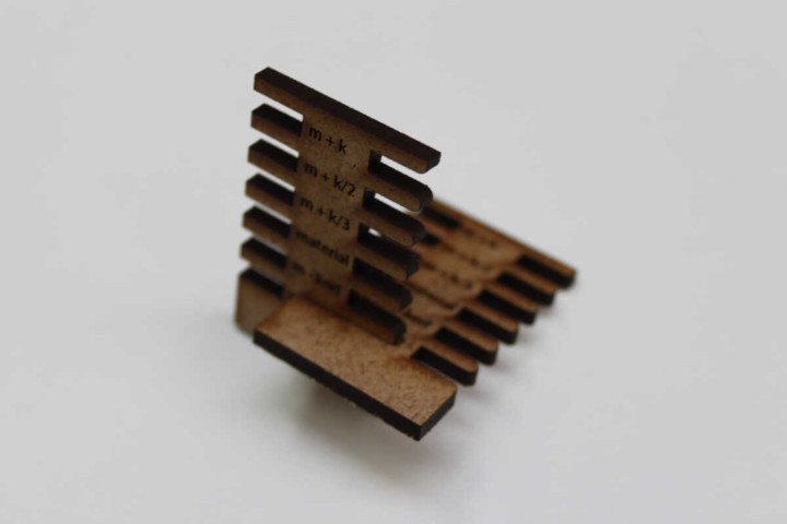
Taking that measurement I made a parametric kerf bar with material (m) and kerf (k) variables. The best fitting section is material - kerf/2:
Octogon Chips (With Chamfer)
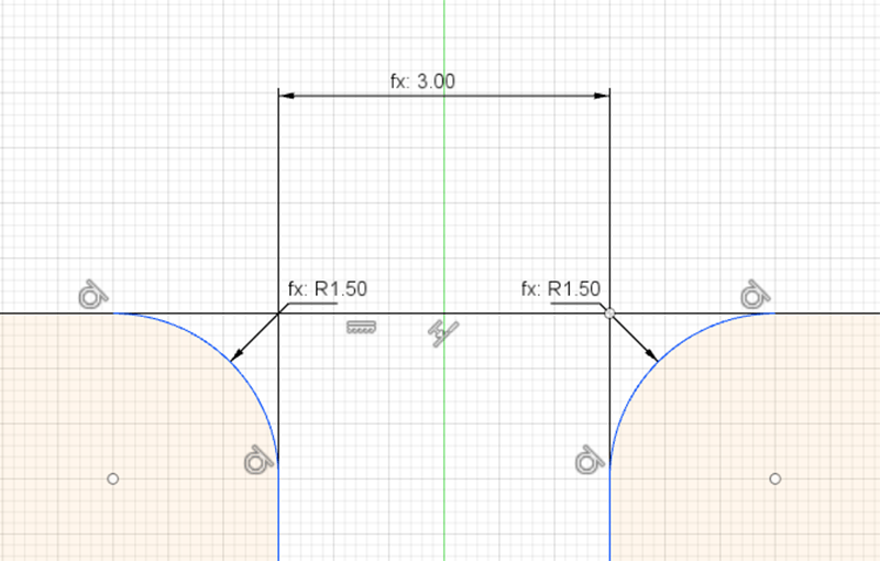
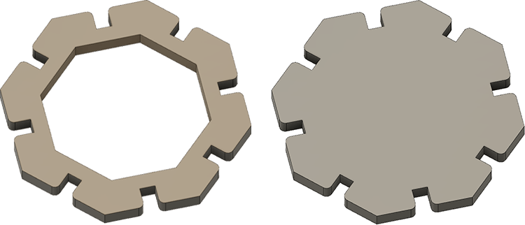
Next I drew some octagonal shapes to give more directions of connection. To start, I created a parameter called 'material' (currently set at 3mm) which will allow me to alter the shape easily for different material sizes. After drawing an inscribed, 8-sided polygon I added the slots. The following image is a close-up of the chamfered slot showing dimensions. These were set using the user parameter material and the radius is material/2, so would change depending on the thickness of the material. I then drew a slot and dimensioned the long side 'material * 3' and the short side 'material'. I have also created a parameter called kerf, but I'm drawing these shapes before we have had a chance to characterise the laser cutter, so I've set it as a placeholder 0.15 mm. I used the 'midpoint' constraint to pull the slot into the centre of the side of the octogon. To do this I selected the short side of the slot, then clicked the midpoint button, then finally clicked the edge of the octogon.
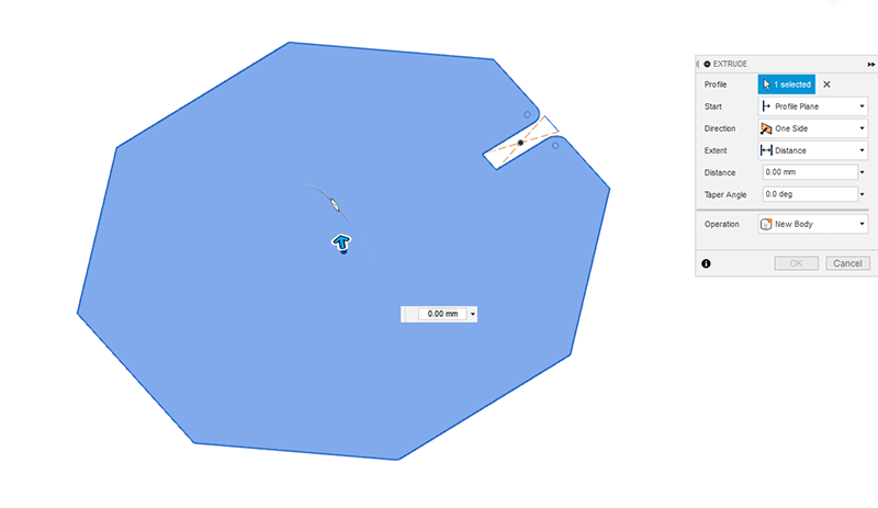
Once the slot was positioned I extruded the shape using the material parameter. The field currently showing 0.00mm was changed to 'material'.
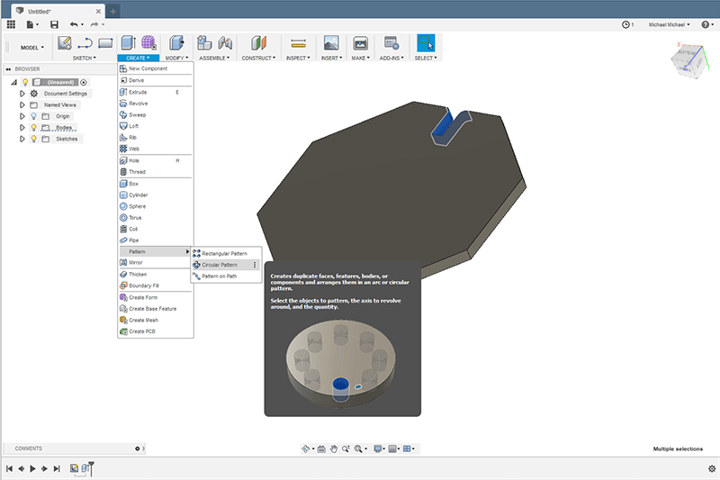
The next step was to select the faces I wanted to clone to the rest of the part. I pushed the slot around the shape using the circular pattern creation tool (Create > Pattern > Circular Pattern) with the operation set to 'Cut'
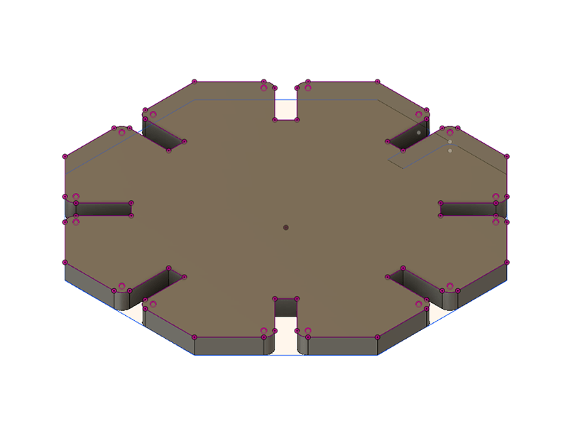
This creates the following shape:
Bridges
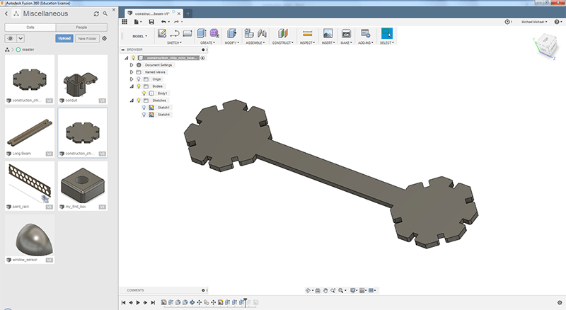
I like bridges - who doesn't? So, when I was drawing these shapes and imagining what I could build with them, I kept coming back to bridges. I wanted to keep this set as simple as possible, so I created two beams - a long and a short beam, to aid the building of bridges and towers with the construction chips. I set the short beam as 100mm, then calculated the length of the longer beam using Pythagoras' theorem to allow connections at 45 degrees that also connect vertically or horizontally. To allow connection in the third plane I added two holes in the centre of the octogon chips:
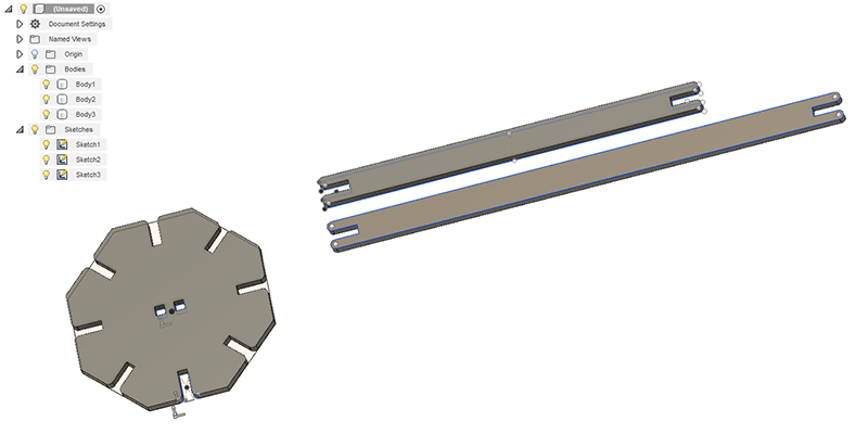
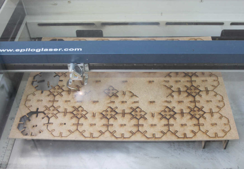
Once I was happy with the shapes I exported a .DXF file from Fusion 360 and sent a job to the laser. It cut the shapes in a strange order - I think that the vector optimisation option was ticked:
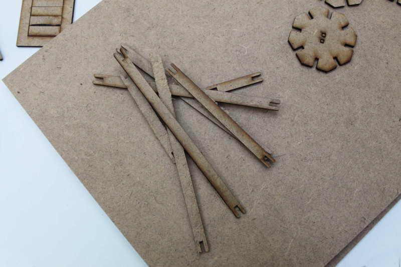
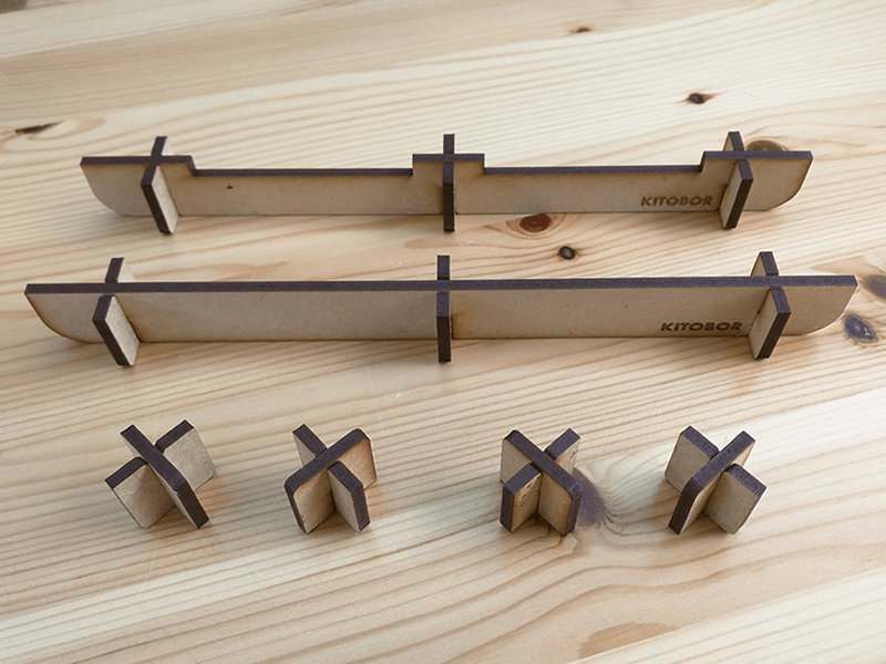
Here are the finished beams and chips, cut from 3mm MDF:
Next I measured the thickness of a cardboard box we had in the lab and changed the parameters in Fusion 360 to 5.9mm material thickness - changing the 3mm shown here:
Arachnid Construction System (ACS)
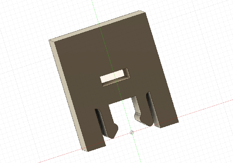
I wanted to try something slightly different once I had a basic set of the construction chips with chamfered slots (the first spiral). This time I made an Arachnid Construction System, centred on an octogonal cephalothorax piece that can be connected to different sizes and shapes of legs, heads, tails and other appendages to make fantasy arachnids that are vaguely based on real arachnid biology. The goal was to create a more solid fixing than the chamfered slots. Here's my first attempt at modeling the joint in Fusion 360:
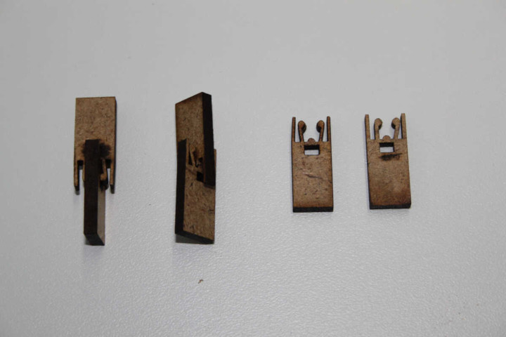
The joints did not work very well in MDF at the sizes I was making them. The pins snapped in many cases. I reverted back to the standard slot. I would like to investigate the other joints further, but I need to consider the material more carefully as the joints require a little bit of spring to work properly.
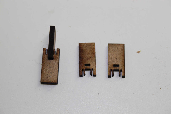
I tried a couple of designs, but as you can see in this image the MDF broke too easily. I decided to abandon this experimentation for now and concentrate on getting the models made.
Building on last week, here is my first attempt at constructing an assembly from components in Fusion 360. I was a little worried about how difficult process was going to be to start with, but the process is actually incredibly easy. Basically you click on one joint, then another and rotate to the correct orientation. It's that simple!
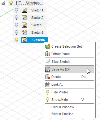
Once I was happy with the clearances of my models I went ahead and cut the arachnids out of 3mm MDF. First of all I had to export the sketch as a .DXF file.
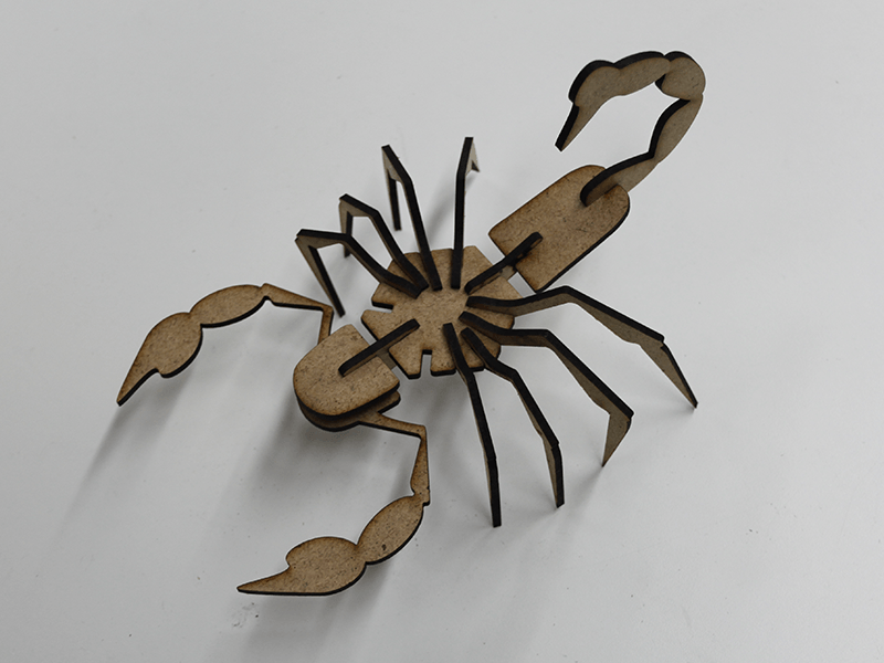
Once the parts were cut, the assembly was very easy. Here's the scorpion:
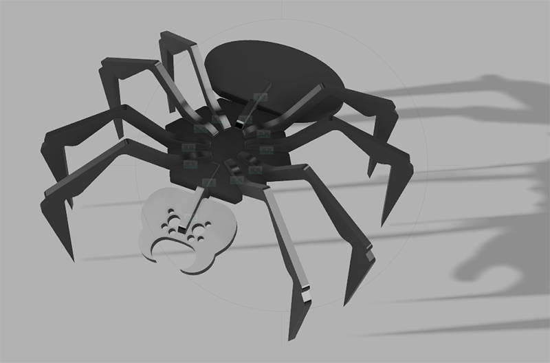
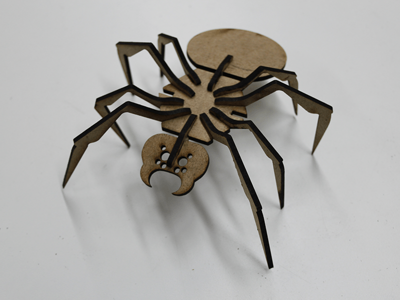
And here's the spider:
Group Assignment
Epilog Helix Laser Cutter Characterisastion
I helped detail the instructions for the Epilog Helix laser.
| Bed size: | Maximum material thickness: | Wattage: |
| 610mm x 457mm | 216mm | 40 |
Obstacles and Solutions
Transfer tape
Not an obstacle to learning, but a physical one this week. The lack of transfer tape did cause a couple of problems. We improvised with paper parcel tape, but I suppose transfer tape has a lower level of adhesive tackiness. The parcel tape gripped the vinyl cuts too well and was difficult to remove.
Laser stand-offs
One who shall remain nameless to protect the innocent managed to start a fire this week...
To combat this issue I made some stand-offs to lift the stock away from the metal baseplate, I found this gave much cleaner cuts because the smoke could easily escape and didn't burn the back of the stock. As an added bonus it seems to set things on fire less as well.
Dead Ends
This week I went down a few dead ends - here are some of the things i played around with that I didn't take forward. The first one is a chip with a cutout. The idea was that I could make a smaller slotted chip from the inside of the chip. This is still an idea that might have some legs, but this incarnation didn't work very well. The width of the face behind the slot was designed to accept another chip at 0 degress, 90 degrees and 180 degrees, but the length of the slot is too short and the mechanical connection between chips was not good enough.
Before deciding on the seperate beams I considered having only two types of chip, a longer 'bone' shape and a shorter one. The idea is pictured below. I didn't take it forward as I felt the two beams were a better solution and created cleaner structures. The 'bones' always need an extra octogon whenever a connection is made.
Downloads
Right-click and choose 'Save Link As...' or similar to download.
Skull Vinyl Sticker
Skull Sticker: Adobe Illustrator .ai (93KB)
Parametric Kerf Comb
Kerf Comb: Fusion 360 Archive (77KB)
Bridge Construction System (BCS)
Construction Chips: .SVG (29KB)
Anachrid Construction System (ACS)
References
Online
- Epilog Laser. (2018). Epilog Legend Series: Epilog Mini 18, 24 and Helix. [online] Epiloglaser.co.uk. Available at: https://www.epiloglaser.co.uk/laser-machines/legend-laser-series.htm [Accessed 6 Aug. 2018].
- Makezine (2019). Accounting For Kerf: How Much Material Is Really Removed By Your Cutter? [online] Makezine.com Available at: https://makezine.com/2018/12/31/accounting-for-kerf-how-much-material-is-really-removed-by-your-cutter/ [Accessed 2 Jan. 2019]
- Roland DG. (2018). Roland GS-24 Desktop Vinyl Cutter. [online] Available at: https://www.rolanddg.co.uk/products/vinyl-cutters/camm-1-gs-24-desktop-vinyl-cutter [Accessed 6 Aug. 2018].
- Williamson, J. (2018). Figuring out kerf for precision parts. [online] Ponoko. Available at: https://www.ponoko.com/blog/ponoko/figuring-out-kerf-for-precision-parts [Accessed 6 Aug. 2018].