TASK TO DO:
- Design and 3D print an object (small, few cm) that could not be made subtractively.
- 3D scan an object (and optionally print it).
- Test the design rules for your printer(s) (group project).
- I learned both 3D printers i.e Accucraft i250+ and JULIA by testing them.
- I designed and made an objects which can't be made by subtractive method.
- I Scanned an object.
Group assignment:
WHAT I HAVE DONE:
What is additive and subtractive?
ADDITIVE - It is a process of build any object in layer by depositing any material.
SUBTRACTIVE - a process by which 3D objects are constructed by successively cutting material away from a solid block of material.
Why 3D printing is unique?
Additive refers to a process of starting from nothing and adding material until the desired object is produced. In additive techniques, 3D printing is different in its manufacturing process as it successively add material to the object instead of forming everything at once. Therefore every area of the object is accessible during the manufacturing process.
The main advantage of a 3D printer, is customization, which means that you are able to print any design no matter how complex it might be. So you are able to create objects that are encased in other objects and movable or even flexible parts. Basically, 3D printing has the unique ability to produce almost every imaginable 3-dimensional object, which is due to the successive additive technique.
Our instructor Supriya gave us a nice introduction related to 3D printing i.e how to start, clean, set and maintain both printers.
ABOUT PRINTERS :
We have two printers in our lab and I studied both by taking the help of my local instructor(supriya).
1. Accucraft i250+ :-
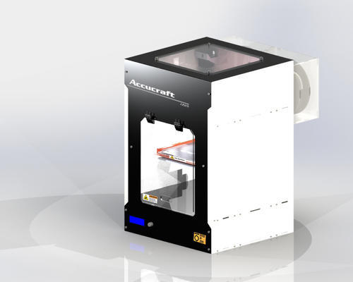
Specification -
Bed area - 250*250*200mm
printing material - ABS, PLA, etc.
single extrude with Filament Diameter - 1.75mm
Before going for any test we have to know about the settings and maintenance of 3D printer.
Accucraft needs two software i.e KISSLICER and REPTIER HOST for making the gcode file.
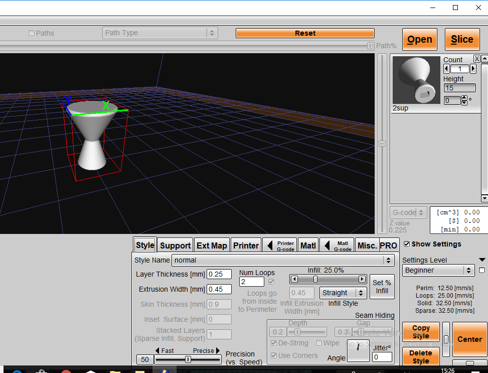
Kisslicer -
We can choose any of these option Beginner, Medium or Expert. Beginner don't allows to change more settings And expert allows to change everything. It is better to put settings in Beginner mode for new people.
Here I choose the Beginner option and explain settings.
Step 1: Open the .stl file and make settings as per you required.
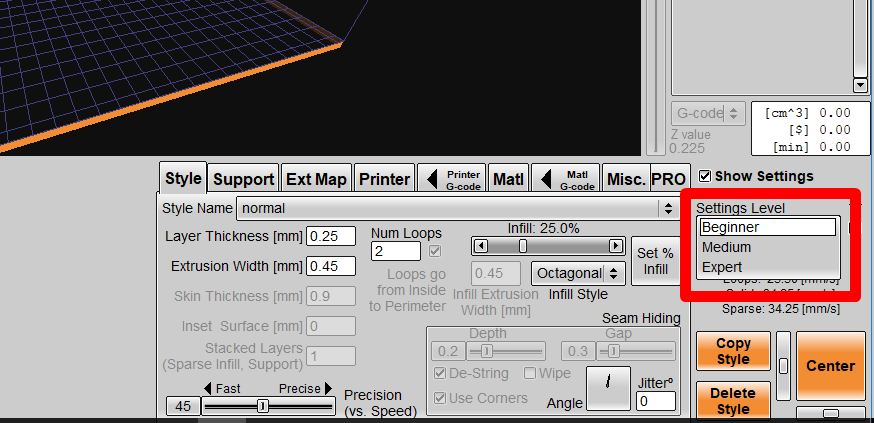
1. STYLE NAME - select style name normal, fine, superfine according to need.
2. LAYER THICKNESS - It decides surface finish. Here layer means horizontal layers. If layer thickness is more then it gives rough surface. 0.15mm is minimum layer thickness we can provide and 0.5mm is maximum thickness. 0.25mm is standard.
3. NO. OF LOOPS - This is a no. by which nozzle make complete round to form object wall. As no. of loops increases cracking problem decreases.
4. EXTRUSION WIDTH -
Extrusion width* No. of loops = Skin thickness
Extrusion width is width of extruded material. 0.45mm is standard but it can increase after few days. Extrusion width can increase due to wear and tear of nozzle.
5. INFILL - You can set infill according to requirement of density of object.
6. INFILL STYLE - Octagonal gives more strength than circular and circular gives more strength than linear.
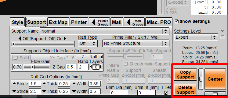
7.SUPPORT NAME - We can keep support ON or OFF and we can also change density of support. As we go from coarse to extra hard then density of support increases.
Download the tutorial for complete settings file from here:
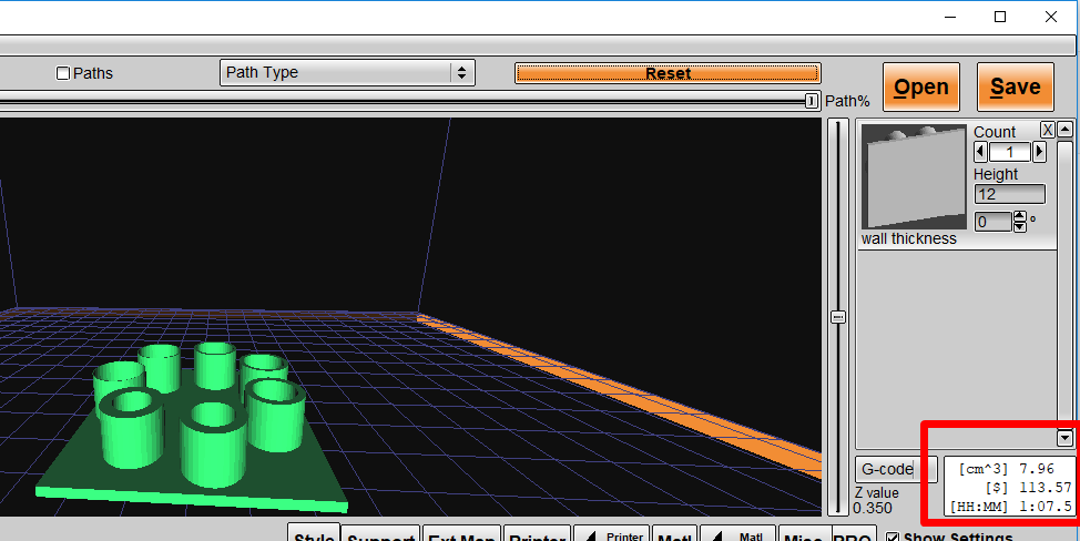
Step 2: After settings click on the "slice" button and we get volume of the object and time for printing the object.
Step 3: Save the file (G-code File).
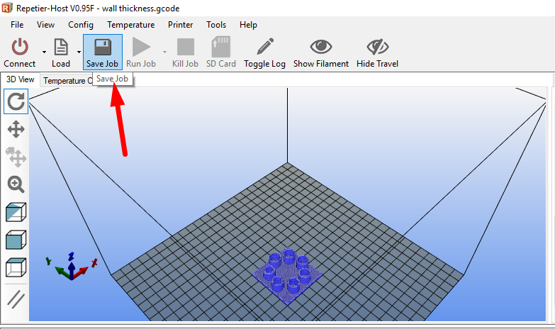
Repetier host -
In this we have to just load the gcode file which made in kisslicer and make the gco. Save in binary format.
Maintenance and settings of Accucraft-
1. Clean the bed and extruder - Bed of this printer is made up of glass. we can remove the glass and clean it by using water. Clean the extruder by using smooth sand paper. Just clean the nozzle by applying sand paper around it, not on the nozzle hole.
2. Fill/ remove the material from extruder - For remove the material from extruder, just heat the nozzle and hold the material at the upper side of extruder and
3. Bed level- Took one A4 size paper and fold it. Place the paper on the bed and check the friction between nozzle and bed, loose or tight it as per need by screws which are at bottom of the bed.
4. Material changing - Material holder is at the backside of printer. We can remove it and change directly.
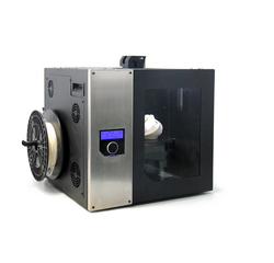
2. JULIA-
In vigyan ashram most of the objects are printed on JULIA 3D printer by Frakralworks.
 Specification-
Bed size- 210*250*260mm
filament size - 1.75mm
Printing material - ABS, PLA, carbonfill(ABS), Copperfill(PLA), Creoflex, Woodfill(PLA),etc.
The printer software supports .stl and .obj files via USB or SD card.
For this we need only one software i.e frcaktory.
GROUP ASSIGNMENT -
We test our JULIA 3D printer by different way as follow:
1. Orientation test -
Here we tested a simple L-shape object by changing its orientation of printing and check the supports, strength. The objects were sliced together.
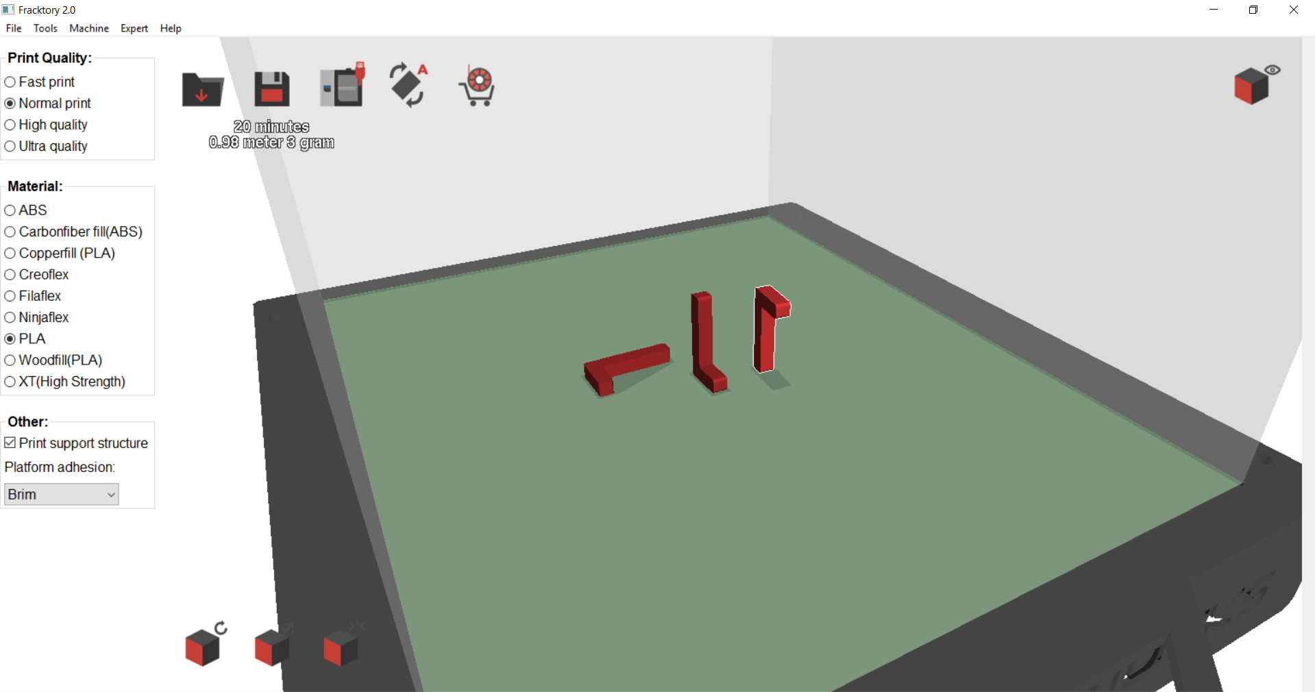
Objects sliced in software and save G-code in the SD card. Apply glue on the julia bed and select the file which you want to print from SD card. Click print.
Result of the test is :
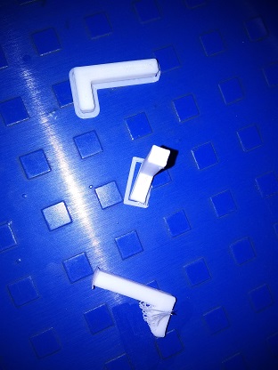
The horizontally placed L-shape has better structural strength as compared to others.
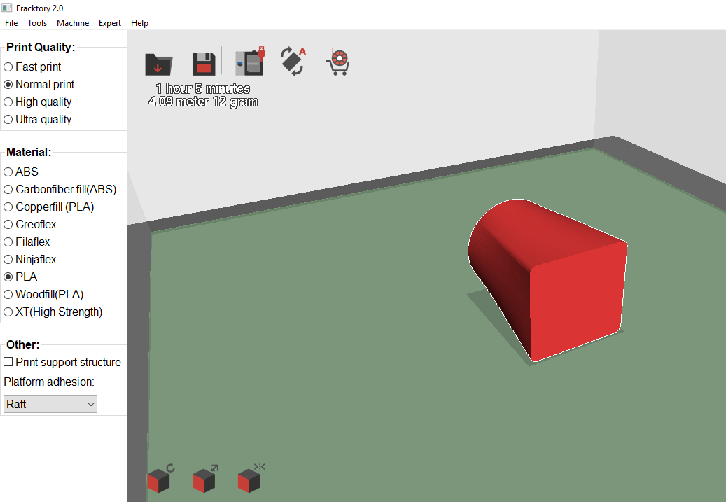
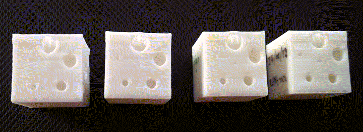
We can only control a few things like quality, material, type of bed adhesion and whether supports are on or off. So test these settings we decided to perform a custom test. we created a simple 20mm cube with some patterns on it. On the top, it has 81 holes of diameter of 1.5mm. On left face it has 3 holes diagonally placed with increasing diameters. On the right side there are 6 holes again with increasing diameters and with fillet on one hole. Then we used the same model created 4 g-codes each exactly similar but with different quality of print. The fast print took just 30mins while the ultra print took almost 2 hours.
By this test we can see only Ultra quality gives us nice results.
On the side, there were 6 holes with increasing diameters and fillet to the central hole.
The central hole has a diameter of 0.5mm while the outside go on increasing till 5mm.
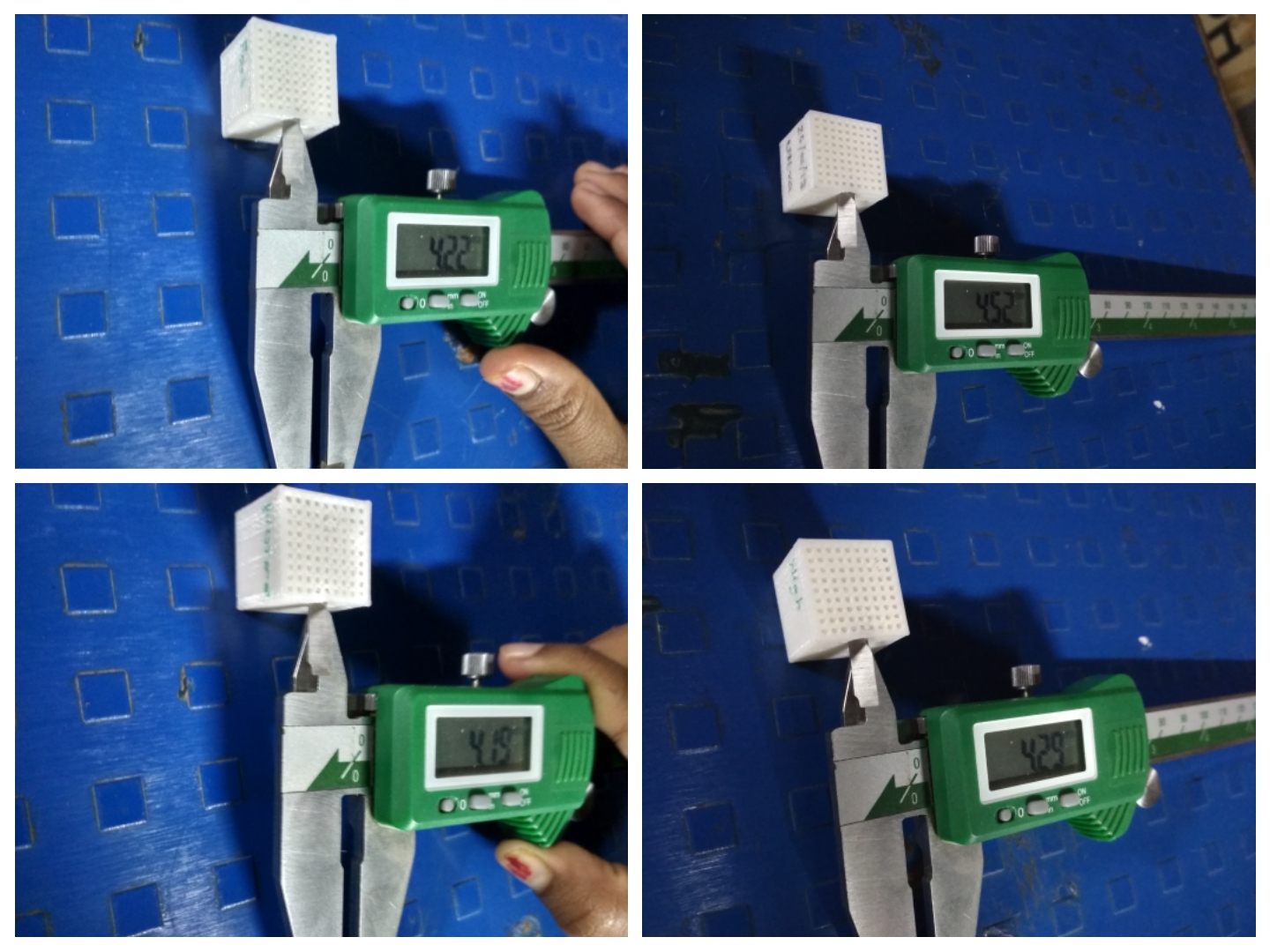 You can see here the biggest hole has 5mm diameter and I checked all printed holes diameter with the help of vernier caliper. The ultra, high, normal and fast print diameters are 4.52mm, 4.49mm, 4.22mm and 4.19mm resp.
As seen, the high and ultra quality prints are acceptable in this case. The rest of the prints don't have fillet. Also the inside hole is not perfectly circular in those cases.
After testing the rules of 3D printer moved towards the individual design and make it 3D printed. I decided to make small parts but useful. For this, I took small round of ashram and decided to make three small customized object i.e Push button for controller board, shoe pin and scissor part.
The reason why each of the object is not possible to manufactured by subtractive method is explained below:
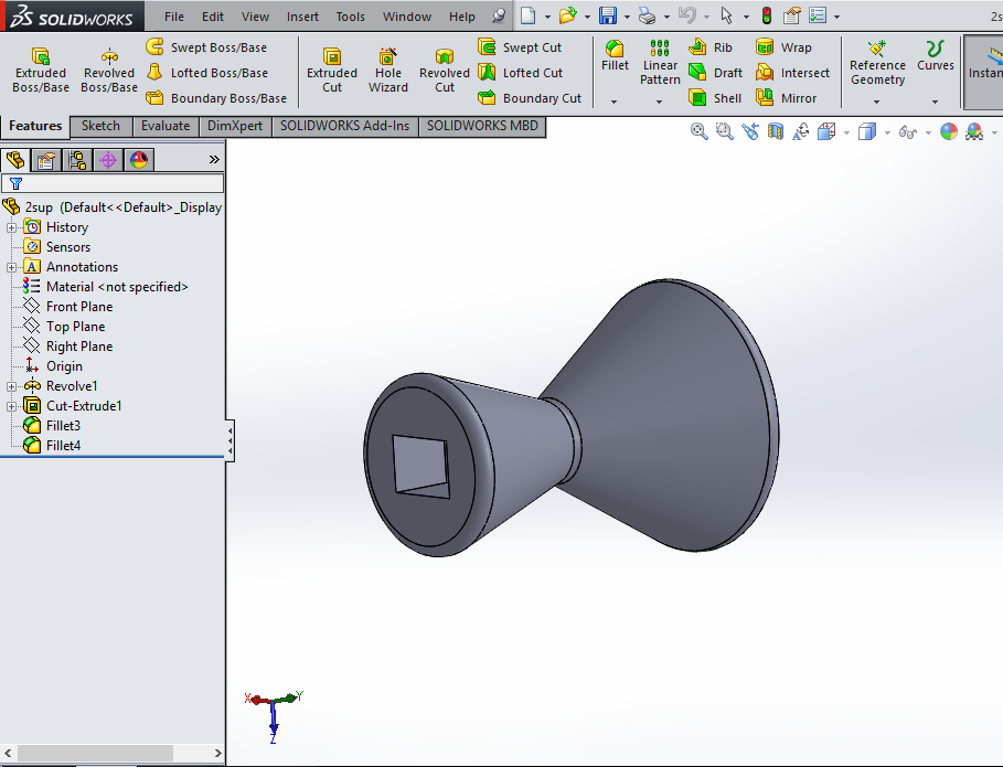
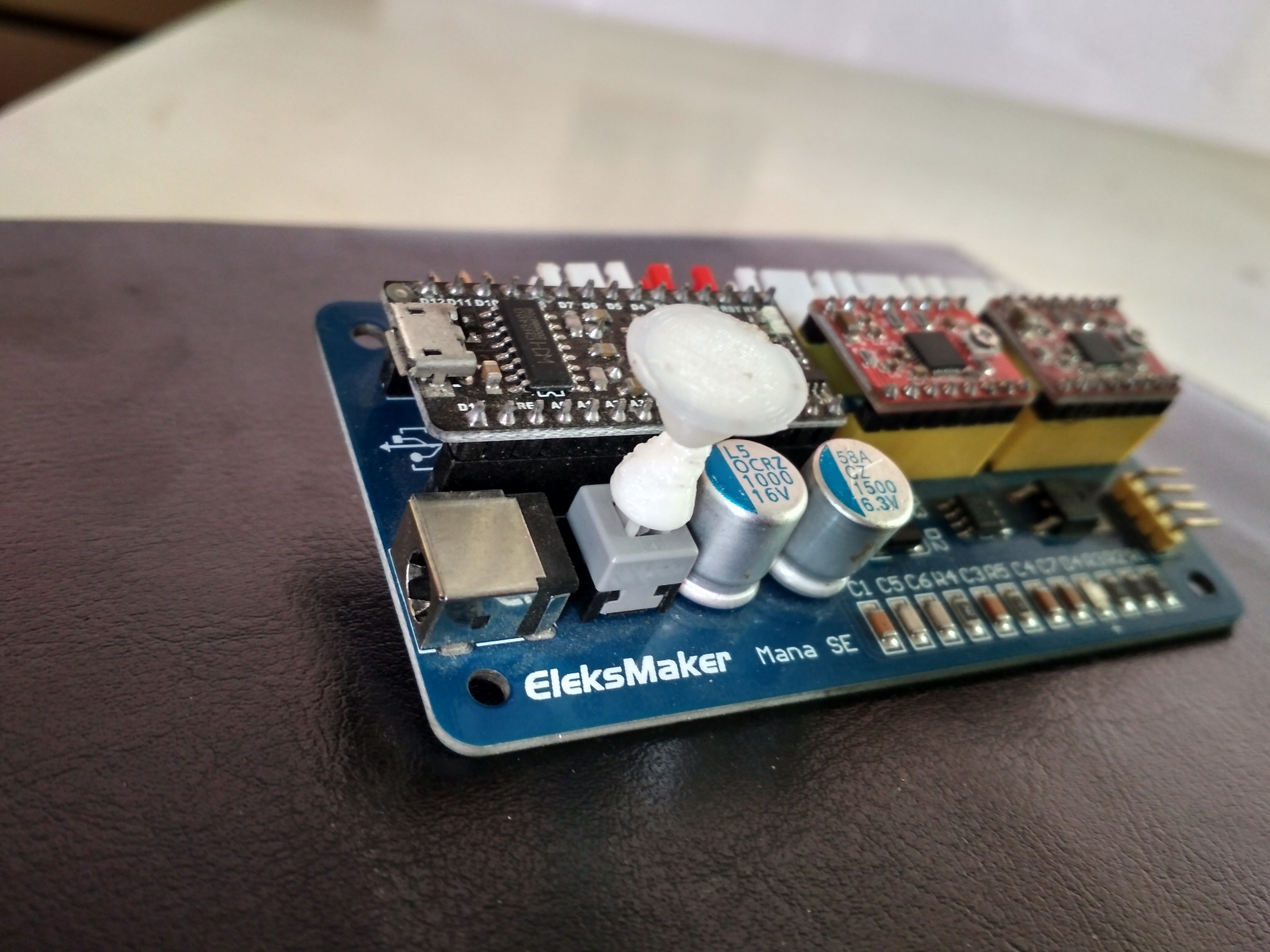
1. PUSH BUTTON -
step 1 : I made 3D part of push button for controller board in solid works and save as .stl file.
Step 2 : Load the file in kisslicer and do the settings as a required :
Set the temperature of printer and press the printer option.
 Why it not made by subtractively?
The following design is difficult by the basic methods such as turning because the job has varying diameters at the end faces, and a tapering geometry at the center which would make the reach of the tool difficult.
Also this would be difficult on the milling machine because on a basic 3 axis milling machine a lot of setup changes would be required, and if we are to avoid this we would need a 5 axis mill that would sort the problem but the machines are un-reachable at the prototyping grounds.
However the method seen possible is casting.
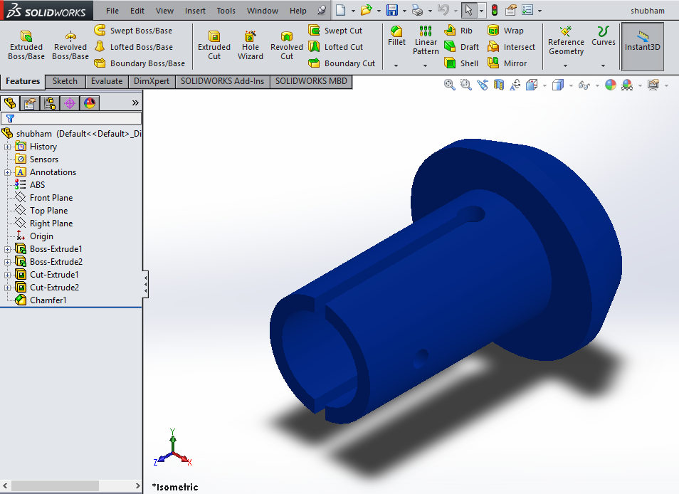
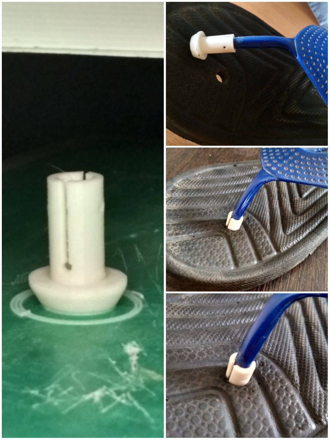
2. SHOE PIN -
1. I made design in solidworks and save as .stl file.
2. Load that .stl file in fractal and select the PLA material and Normal print. Save the file in SD card.
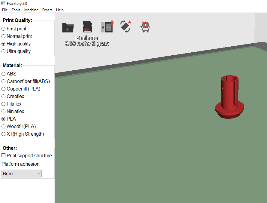
3. After this, I connected the SD card to the JULIA 3D printer. Select the print file and give the print. Here no need to give the temperature because printer itself do all the settings like preheating.
Why it could not made by subtractively?
The shoe pin seems to be difficult to manufacture by turning because of the similar reasons stated above, and more over it has groves which are not on the radial face.
This is also not possible by the methods of casting and forming because of the oddly placed grooves, and variable material thickness at different instance.
Also considering the application, and other subtractive methods for manufacturing, the cost becomes unaffordable.
The possible manufacturing methods seen, using a turnmill that could solve both turning and milling operation simultaneously.
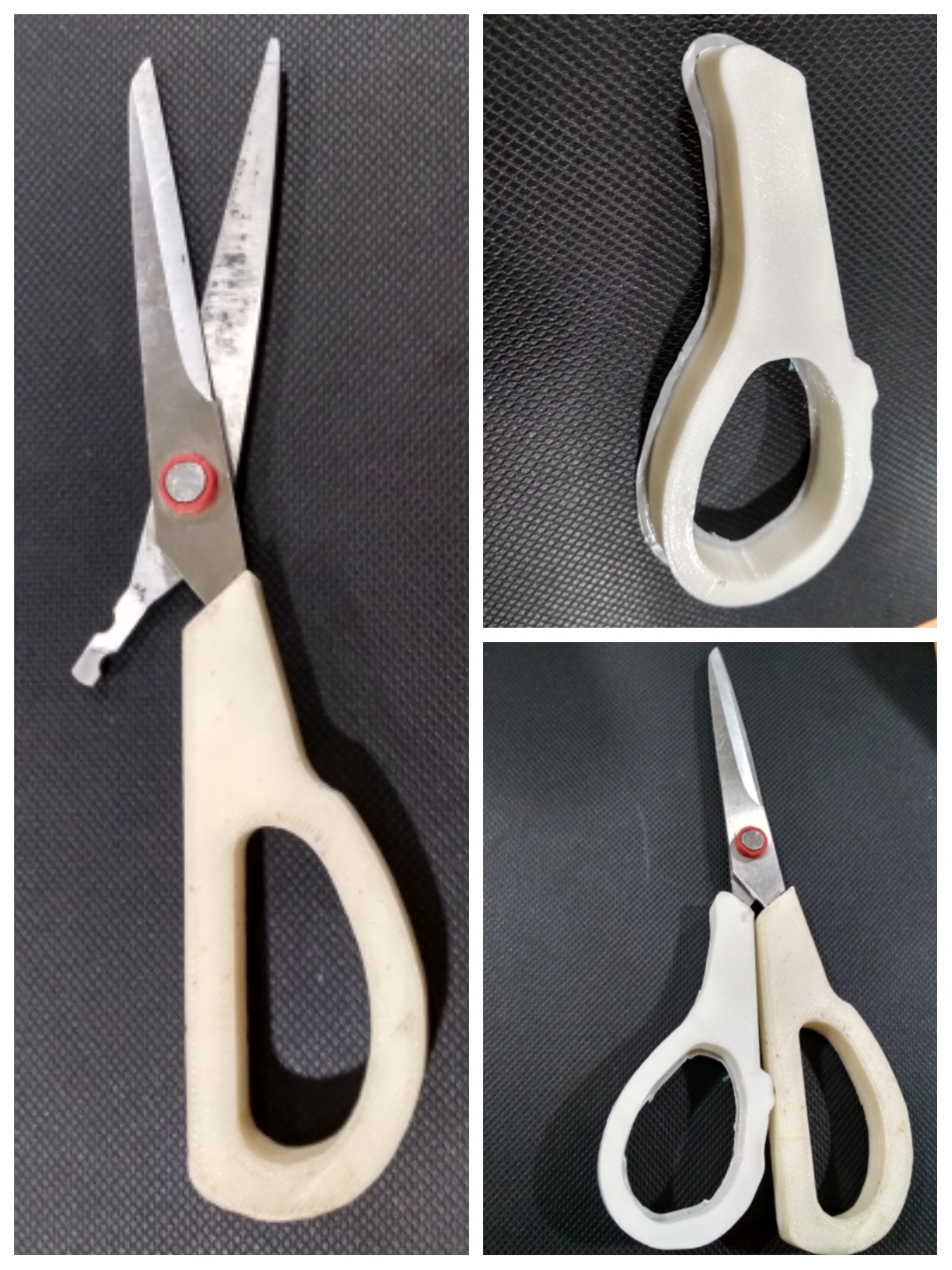
3. SCISSOR PART -
This part also printed in JULIA by following the same command like shoe pin.
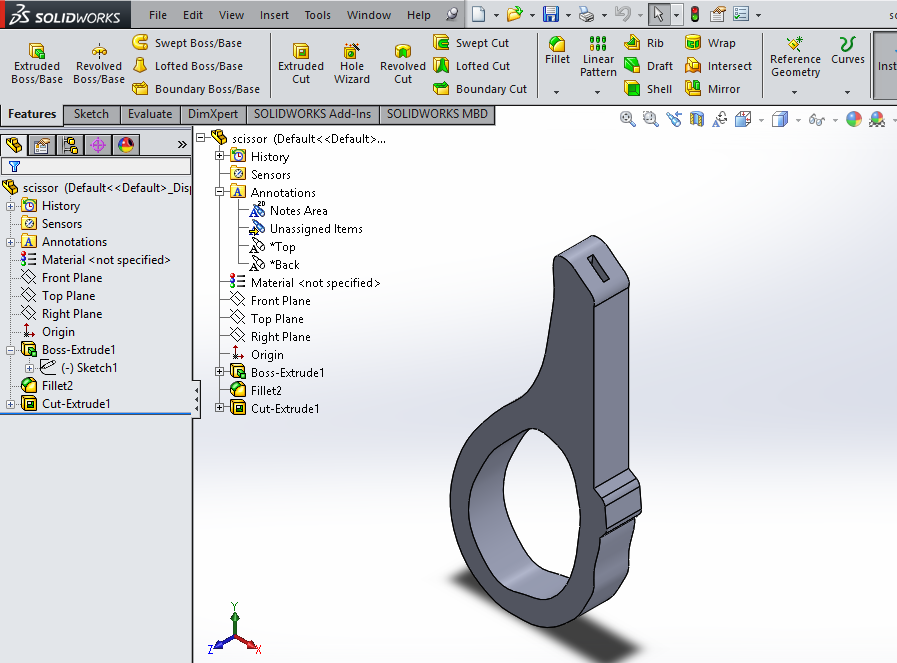
Why it could not be made by subtractively?
The following piece won't be done by the basic machining processes because of the ill placed slots, which would require a drastic change in the setups and a lot of fixturing, only for the particular slot.
Also the tools that would required for the machining would have be customized due to the odd position and the abrupt sizes of the slots.
However this could be done using casting, and few other processes.
In conclusion we see that there are probably very few or rather no jobs that could not be achieved through subtractive manufacturing but the question that needs to be answered before manufacturing is at what cost should the job be manufactured and at what precision?, Also where actually the job is being used?
These questions are basic guiding parameters when we suggest a manufacturing method. Considering the same I had chosen these to be done by additive manufacturing..
Project Part:
I need hinge for my project. So I decided to make 3D printed hinge for my project. I designed the hinge as I want. I made design in solidworks and save file in .stl format.
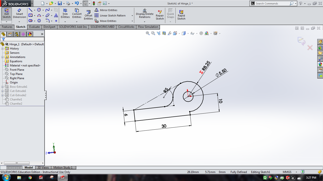
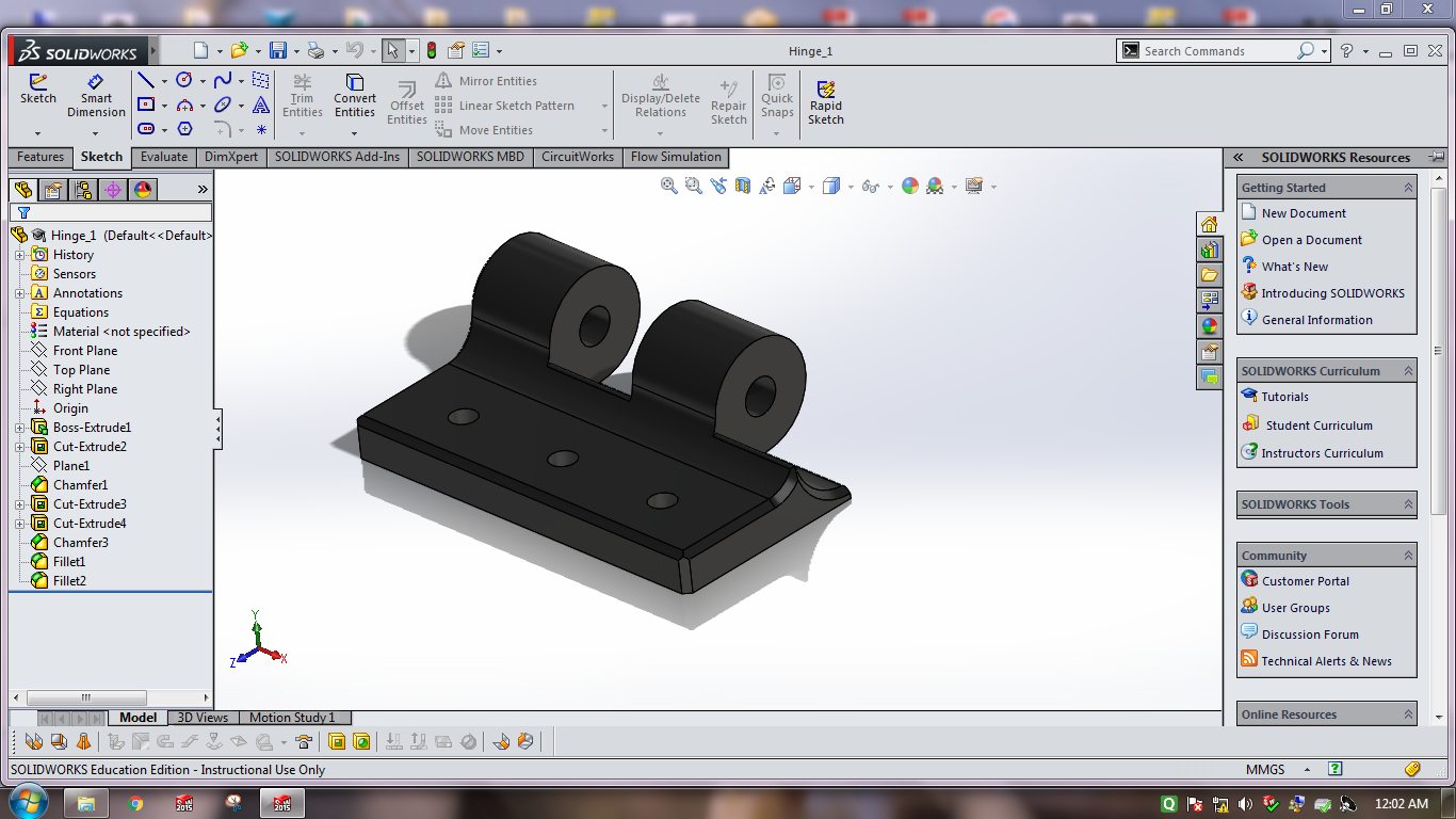
For this it was actually possible to make a hinge that includes no external parts, such as studs or a steady axis.
Hinges like pin barrel hinge, where it has a pin that is guided motion into a barrel.
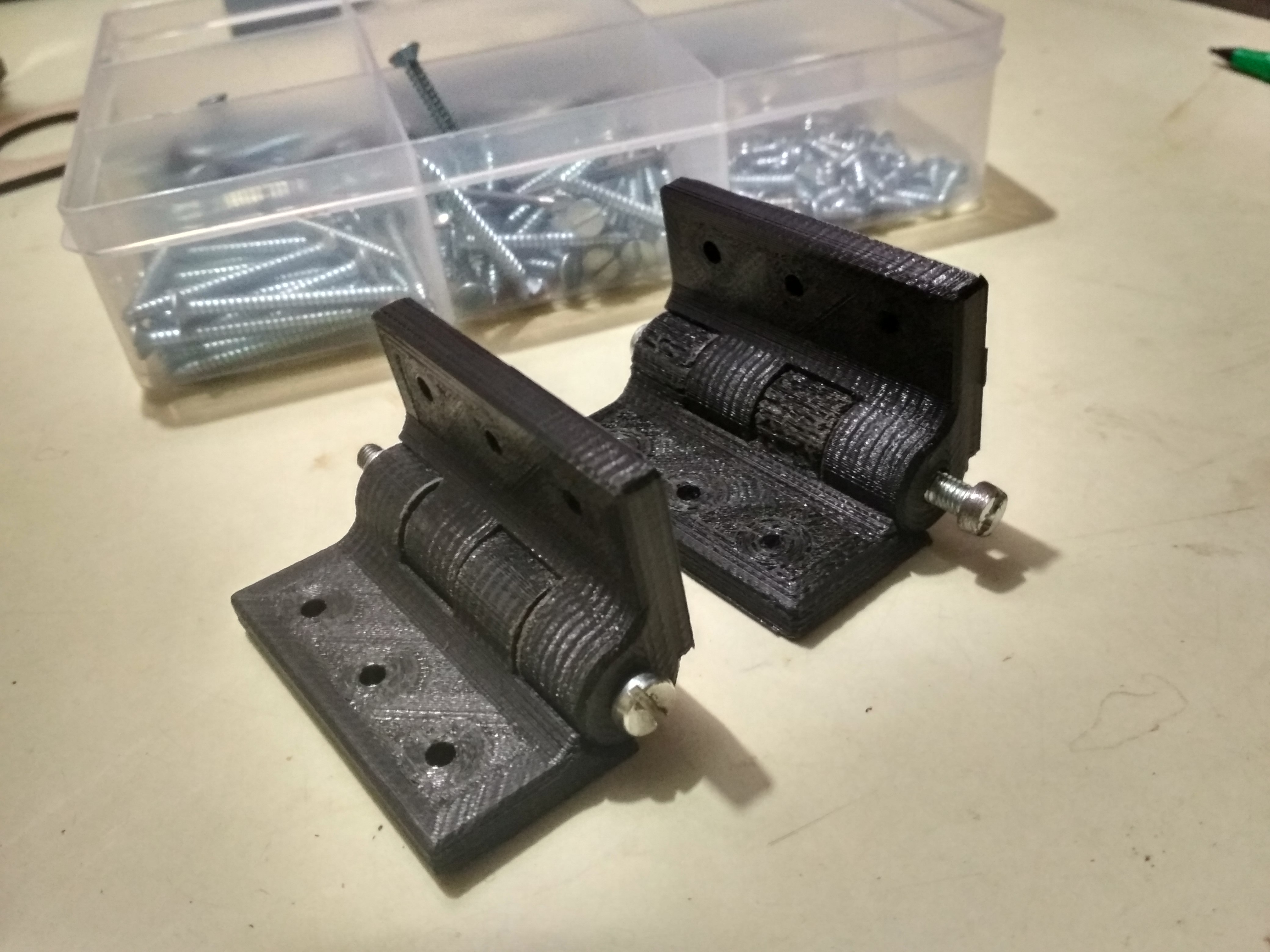
But I had realized an issue about printing this kind of hinge was the printed part consists of a rough surface that might generate higher grade of friction between the moving components, These rough lines are seen on our printer.
Hence I preferred to have the moving axis out of metal to avoid surface friction to have smooth motion.
Advantages of 3D printing-
Best advantage is that we can make customized object by using 3D printer. Also We can almost make anything (i.e what we draw virtually). One of the main advantage of 3D printing is the low cost of labor. 3D printer increase our creativity.
Limitations of 3D printing:-
3D printing is costly. Also it takes more time than any process.
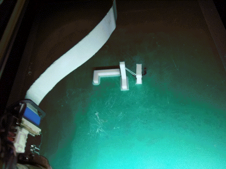
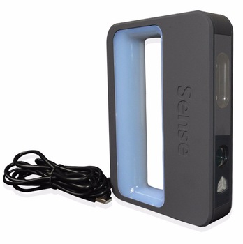
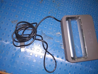
3D SCANNING
we have "sense 3D scanner" which is very easy to handle. First I downloaded the installation file from the official website of 3D sense and then installed the software using a one time pass code.
Specifications are as follows:
Scan Volume:
0.2m x 0.2m 0.2m (min) (Lower the better) and
2m x 2m x 2m (max) (Higher the better)
Depth Resolution at 0.5m: 1mm
Spatial X/Y resolution at 0.5m: 0.9mm
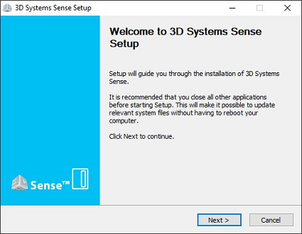
Install Software for 3D scanner
we are using software called as "3D sense" which is the default software provided by 3D sense(company).
Firstly I get the setup downloaded and then install it.
Then connect the scanner to the USB of your machine. If don't connect then it shows the "device not supported" error. So, connect the scanner and open the software, then follow the instructions.
In this we have to scan one 3D object in all direction. This process involves scanning the object with a hand held scanner. The scanner is connected to the PC throughout the process of scanning.
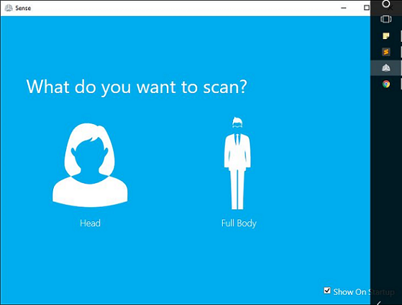
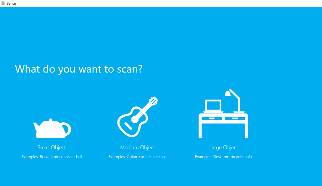
1. Select the required option from them i.e if you want to scan human then choose the human and if its any thing then choose the object option.
2. If you have selecting the object then next question is small, medium or large object.
3. If you have selecting the human then the next question is head or full body.

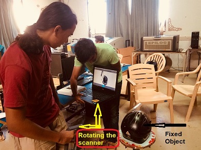
4. Then we are going for the setup of the scanned object. There are two possibilities for scanning:
A. Fixed the scanner and move the object on the turn the table.
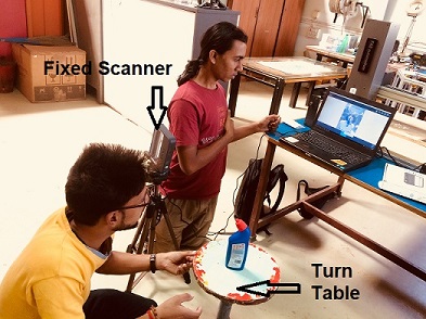
B. By keeping the object stationary and rotating the scanner.
5. Next step was rotate the scanner neatly i.e without much breaking.
It is time to scan now, first time I tried with my colleagues and instructor just for understanding the whole scanning process.
Then I made white paper model which is small but scanner used to loss the tracking. I thought its a night-time so we have to think about light and also I used rotating table. So, I decided to scan myself. Supriya held the scanner. After 2 trial I got proper scanning. Actually its depend upon proper light and holding the scanner stable.
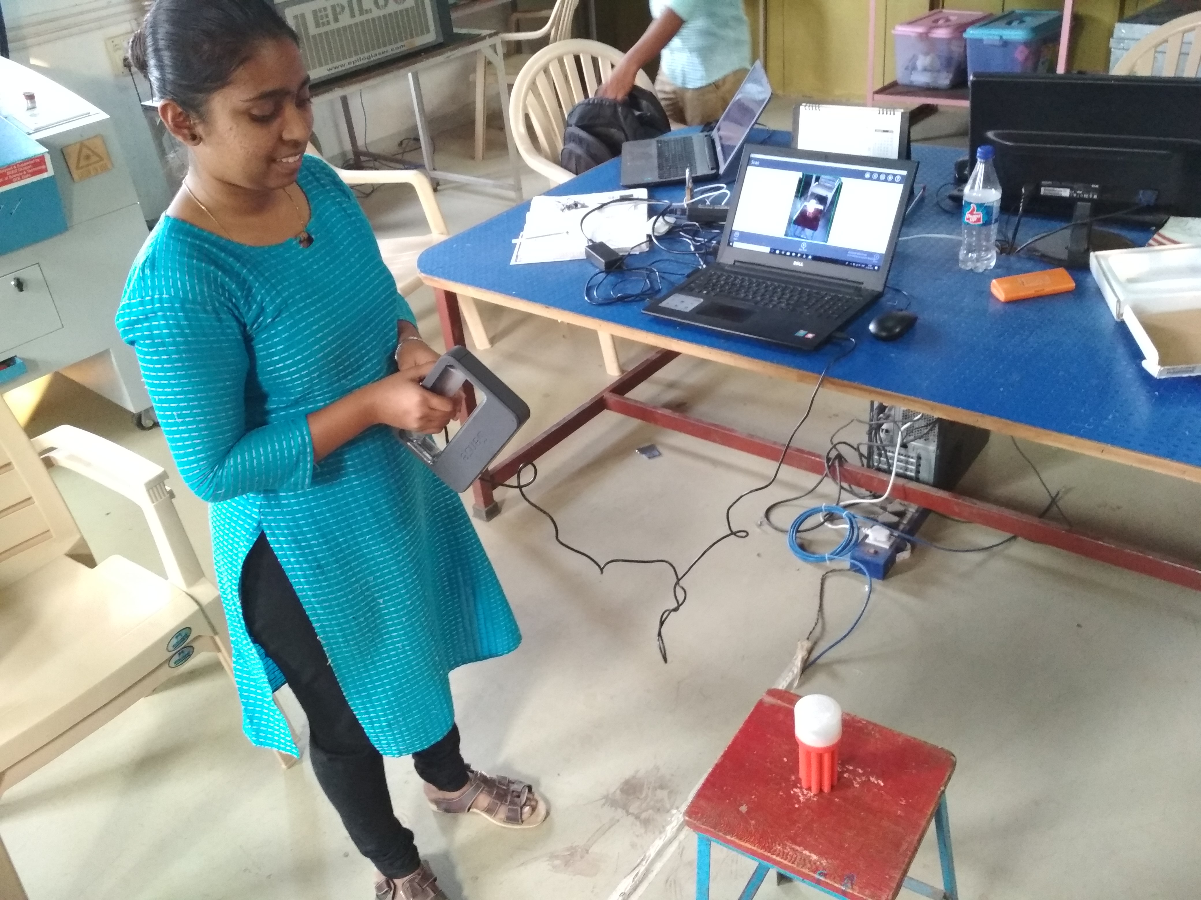
I decided to scan one bottle which doesn't having reflective surface. It is small, placed on the stool. I held the scanner and try to scan it.
Select the object and click on the small object. Now adjust (or move) the scanner until a small green box appears on the object. If you can see your subject properly start scanning.
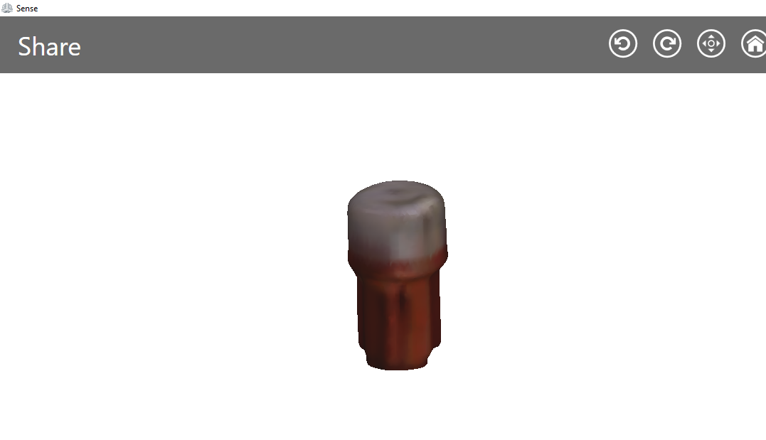
When you done the proper scanning in all directions(X,Y,Z directions) pause the scanning. If you want to erase something there is an option.
There is also an option to solidify or keep the object hollow, I choose to solidify the object.
I saved the file as .stl file.
Advantages of 3D scanning-
Scanner Quickly capture all of the physical measurements of any physical object. It Saves time in design work. We can easily Replace missing or older parts without CAD design.
Limitations of 3D Scanning-
For scanning we have take care many things like light, surface of the object, Rotating object or stability of the scanner, etc. Clarity of the image may not be the best.
You can download original file from here.
My Experience:-
This week was very nice because I like 3D printer. I already familiar with 3D printer so I decided to print different small object but really useful. About scanning , I think this is not precise method because its depend upon various factors like stability of scanner, surface of object,etc.