TASK TO DO:
- Measure the power consumption of an output device.
- Add an output device to a micro-controller board you've designed and program it to do something.
- Described my design and fabrication process using words/images/screenshots.
- Explained the programming process/es I used and how the micro-controller datasheet helped me.
- Included original design files and code.
Group Work -
Individual Work -
WHAT I HAVE DONE:
Output Device-
An output device is any piece of hardware item which utilizes whatever data and commands from your micro controller/processor in order to perform a task.
In this week we have to make board with output device. So, I decided to do this assignment related to my final project. There is a need to make ON and Off water pump. So I decided to make board for water pump.
Designing of the controller board
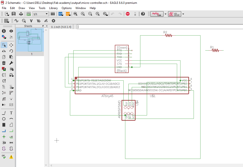
I made controller board with an IC i.e Attiny 44. I have experience with attiny 44. So, I directly go for the schematic diagram..and firstly I select the IC and then other stuff..
This is schematic of the controller board...
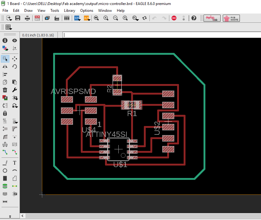
Then routing of the board...
I milled the board and solder it..
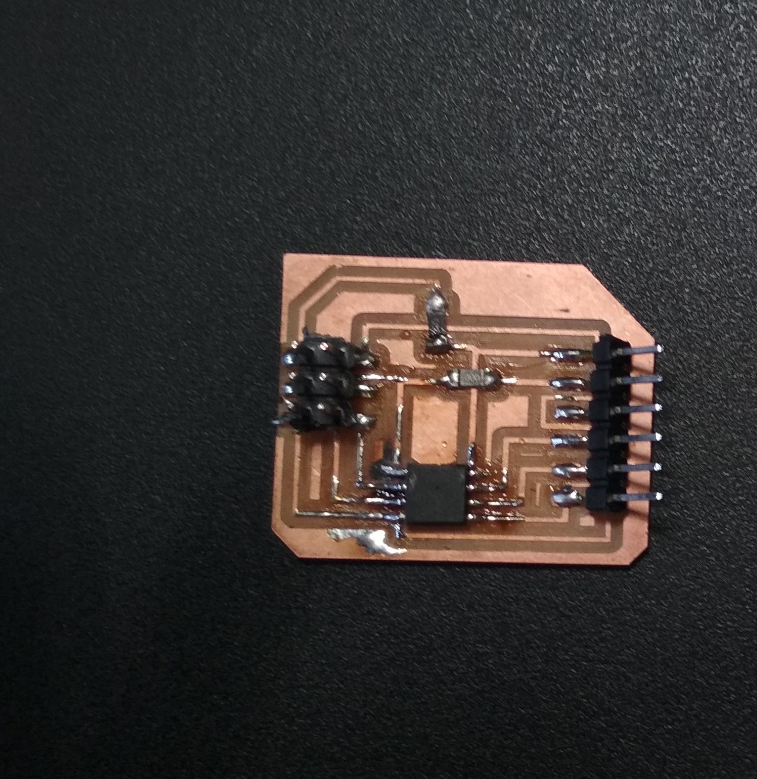
Soldering is completed now and I went to the second that is operator board.
Designing of the operator Board
As per requirement I had to design a board which communicate between the micro-controller and output device. As earlier explained, I had to develop a relay circuit for water pump.
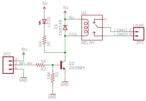
What is Relay?
Relay is electrically operated switch. Relays are switches that open and close circuits electro-mechanically or electronically. Relays control one electrical circuit by opening and closing contacts in another circuit.
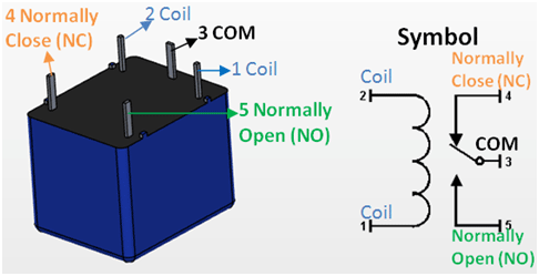
So, I want to start the schematic for relay but I don't have any idea about what components are required for relay circuit. My colleague chaitanya found below image which guide us...
Before going for the schematic I had talk with my instructor and he suggested me to use mosfet only because my pump is DC and mosfet has same function. So, I decided to design the board by using mosfet.
What is Mosfet?
The MOSFET (Metal Oxide Semiconductor Field Effect Transistor) transistor is a semiconductor device which is widely used for switching and amplifying electronic signals in the electronic devices. [From Google]
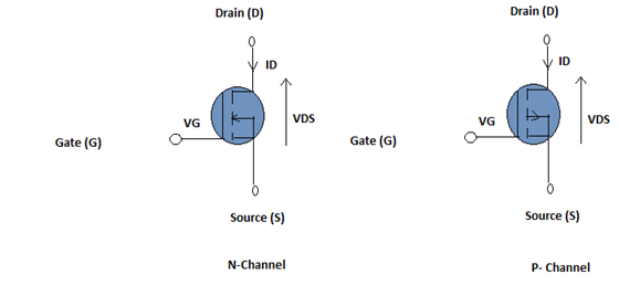
1. P-channel mosfet-
To turn a P channel MOSFET on, you apply a negative voltage to the gate. This voltage is negative relative to ground. In a circuit, you connect the P channel MOSFET’s source terminal to a positive voltage supply and the drain to a resistor connected to ground
2. N-channel mosfet-An N channel MOSFET turns on when you apply a positive voltage at its gate terminal. The voltage is greater than the positive voltage supply at the drain terminal. A resistor between the positive supply and the drain limits current; for an N channel MOSFET, the source terminal connects to ground.
Here I can select any one of the mosfet. I selected available i.e p-type mosfet.
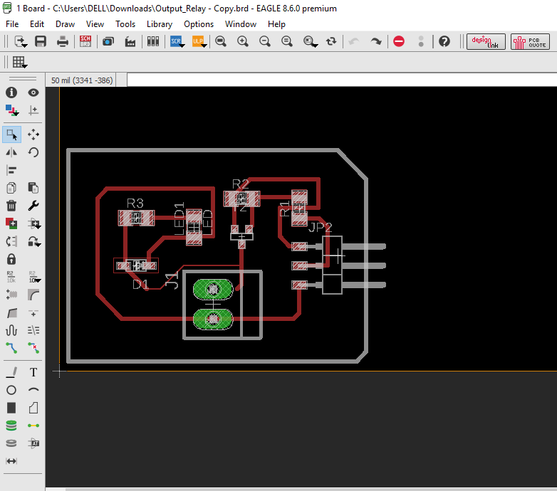
I started the schematic for the mosfet...
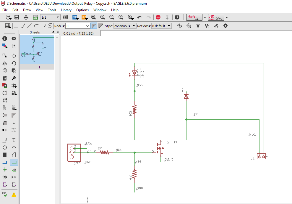
After schematic diagram of the board, I went for the routing..
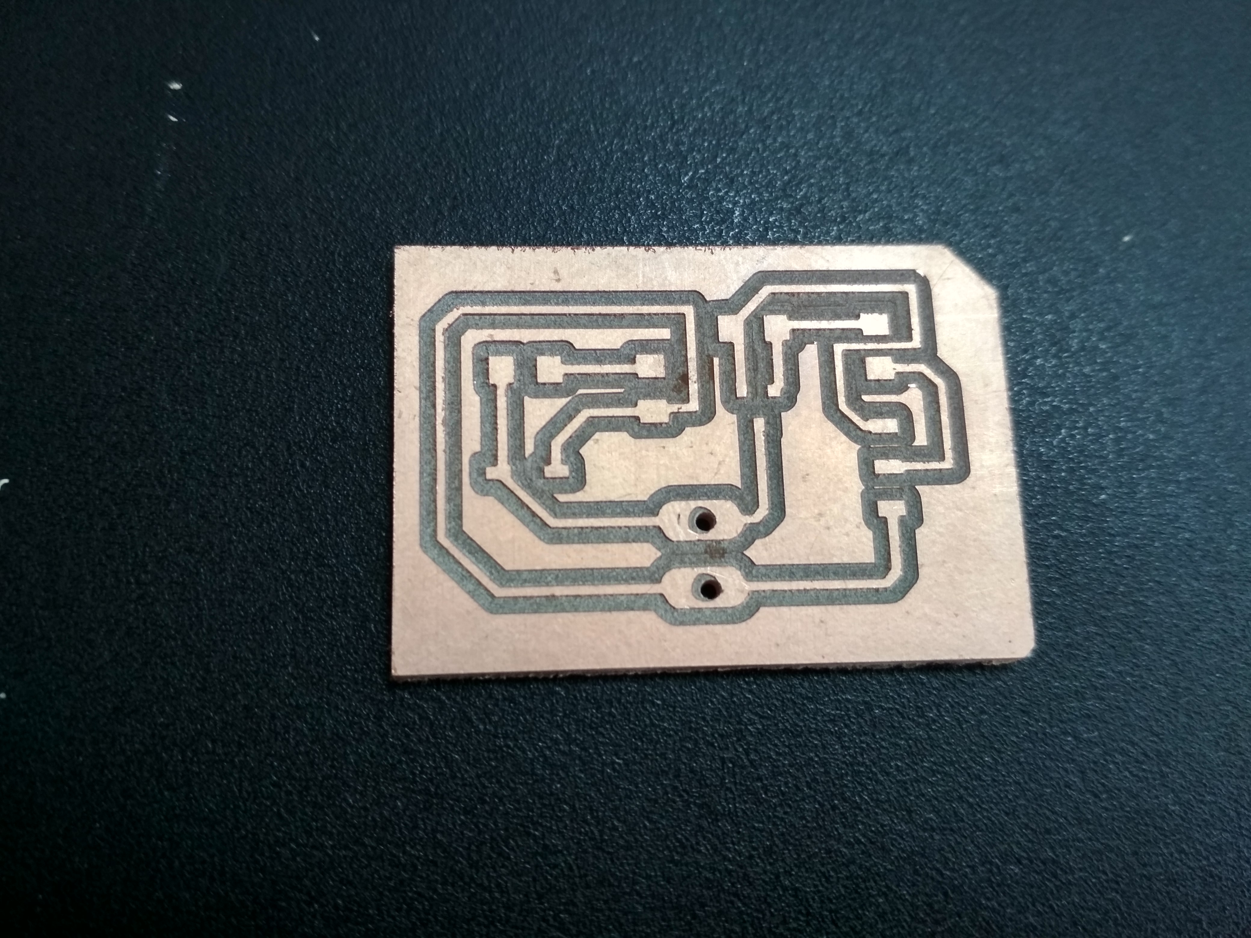
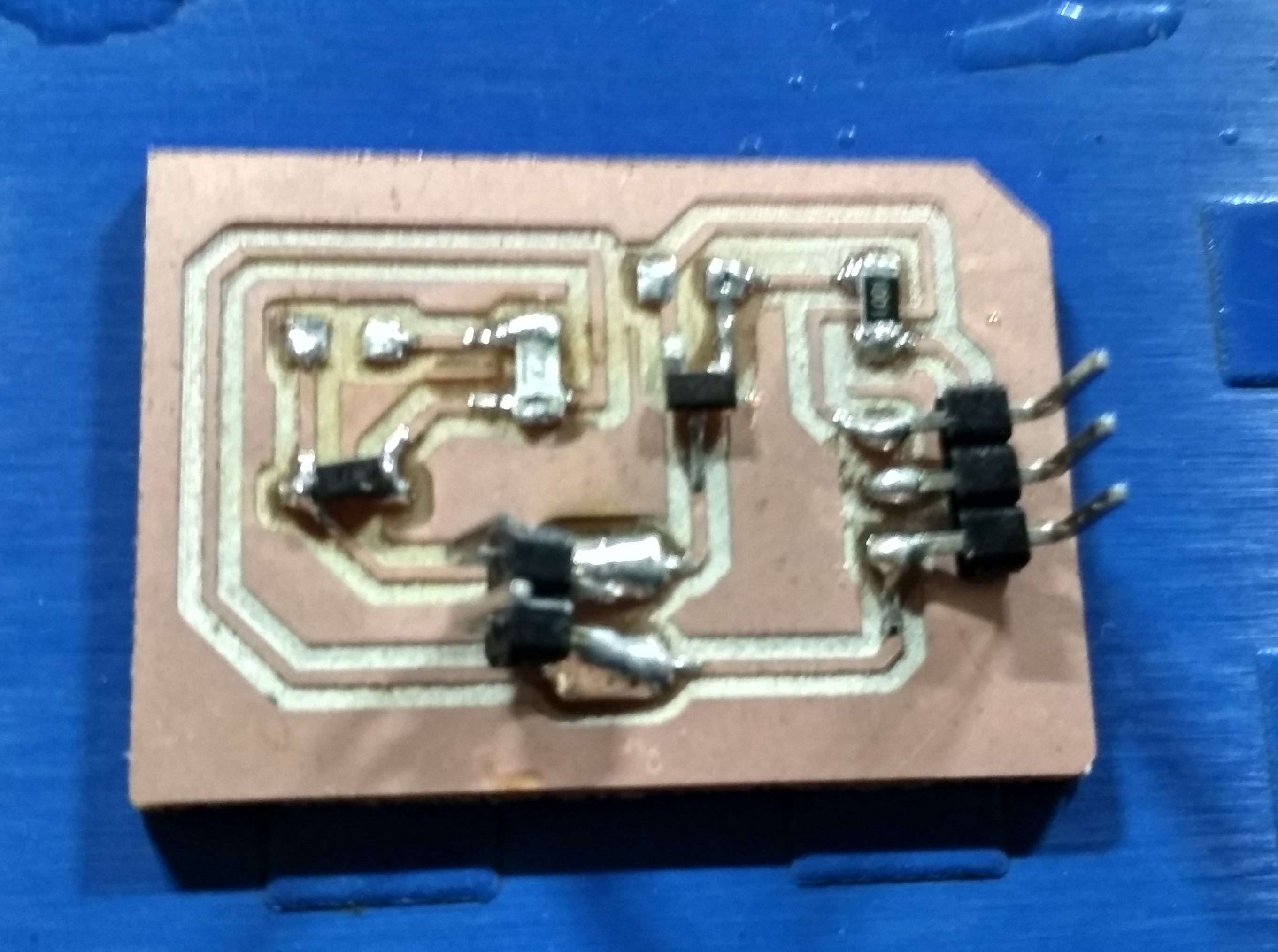
Then I milled the board and solder it properly...
Programming and testing of the boards-
Here I started programming to the board. For this, firstly burn the boot-loader and then program.
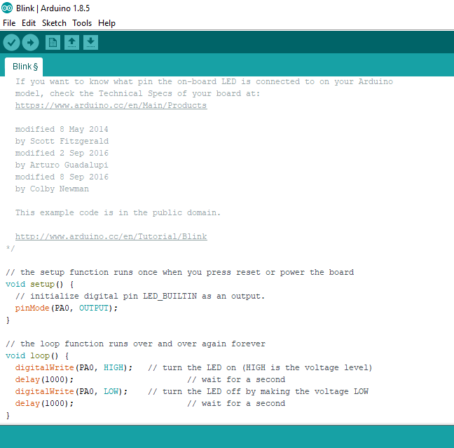
I wrote the simple code in arduino IDE to keep the relay ON and OFF for a particular time. Instead of testing it on a pump, I tested it on a LED to obtain visible results..
I had a simple setup of a laptop connected to the Controller board, which was further attached to the operator board consisting of the mosfet, which was further connected to the LED.
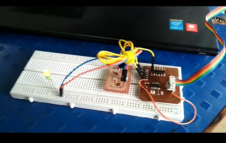
Results of the program you can see here....
Group Assignment:
For group assignment, we have to measure the power consumption of the output device.
We had 12V DC pump, 5V DC motor.
We calculated the power consumption of these as follows:
1: 5V DC motor
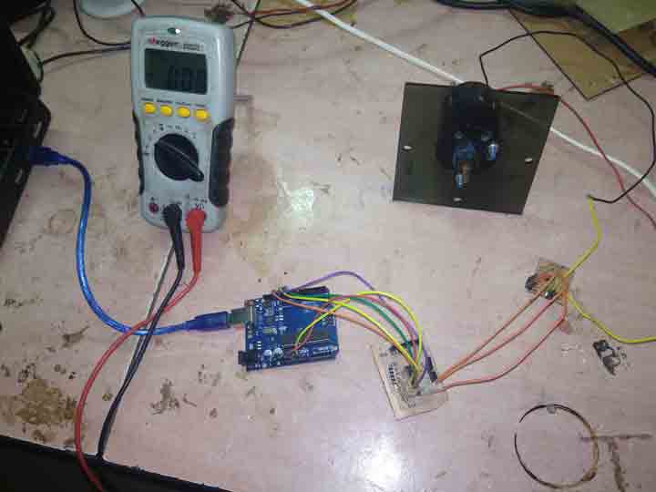
For this we setup the connections directly and powered the motor through the board..
We had one board with P channel MOSFET, rated load of 5V.
The formula for calculating power is P = V * I
Where: P = Power, I = Current, V = Voltage..
To calculate the voltage, we connect the multimeter in parallel to the circuit
The value of voltage is
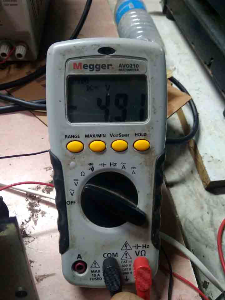
To calculate the current, we connect the multimeter in serial.
The current is
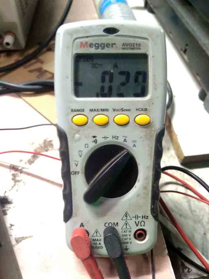
Hence the total power is 1.432W.
2: 12V DC Pump
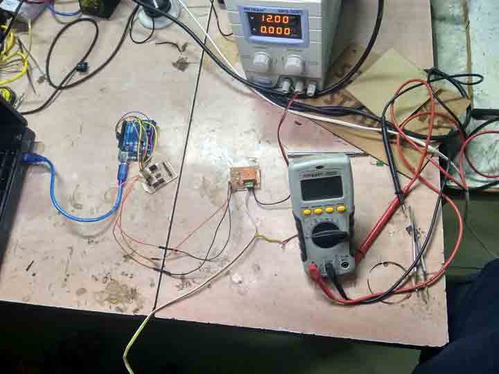
Here we connected the relay in between the ground of the DC power supply and the water pump.
In DC supply we set the max voltage to 12 V and max allowable current to 2amps.
Then we turned on the setup...
The values of max current and voltage appear on the screen of the DC power supply.
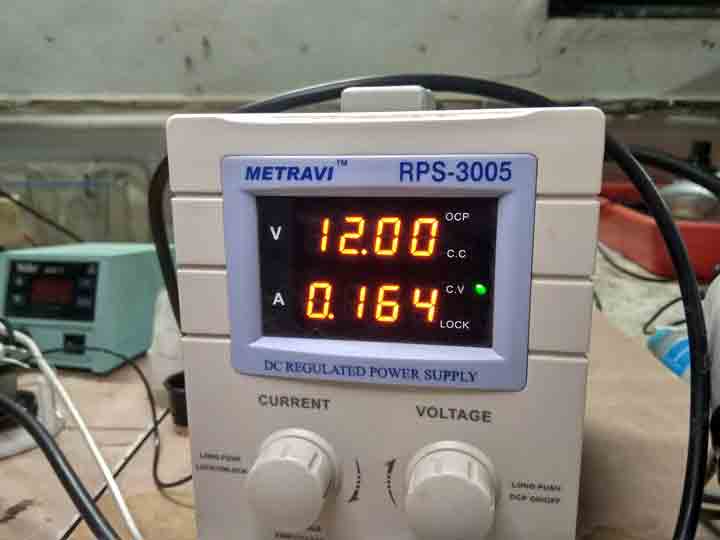
The voltage here is 12V and current is 0.164amps.
So the total power consumption is 1.968W.
You can download original code file from here.
You can download original board file from here.
You can download original relay board file from here.
Learning Outcomes-
In this week I studied about working and function of the relay. This week is really important for my project.