Assignment 15 & 16_mechanical & machine design
Mechanical design
- 01 design a machine that includes mechanism+actuation+automation
- 02 build the mechanical parts and operate it manually
Machine design
- 03 actuate and automate your machine
01 design a machine that includes mechanism+actuation+automation
This week I decided to change the final project that I had to propose the first week and work on a project I had been developing previously: educational analogue machines.
So I decide to use this assignment to work on my project and develop my final project machine individually.
For the same reason, both assignments: mechanical & machine designs are going to be on the same page. All the electronic design & production, and the microcontroller interfacing & programming are in the Networking Assignment, that I also use to fulfil the final project.
PARTS & SYSTEM OF EDUCATIONAL CNC MACHINE
(1) The framework and mechanism of assembly of the machine.
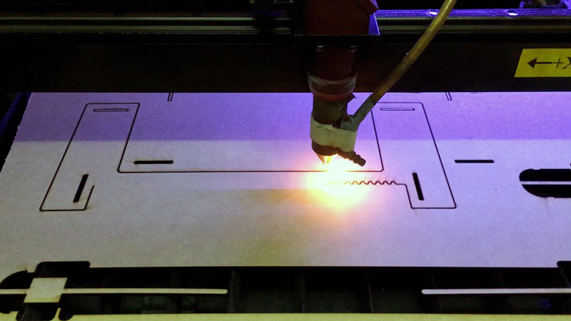
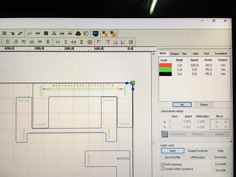
Design: 2D Design
Technology: Laser Cutting
Material: MDF 3mm
(2) The sliding parts for the axes.
Design: 3D Design
Technology: 3D Printing
Material: ABS
(3) Extruder
Design: 3D Design
Technology: 3D Printing
Material: ABS + Basic Electronic
(4) PCB for controlling the axis
Design: Electronic Design
Technology: CNC Router + Electronic Production
Material: Electronics
(5) Programming the machine
Technology: Code Programming (Inputs & Outputs)
Material: Electronics
MATERIALS AND COMPONENTS OF THE MACHINE
FABRICATION
- MDF 3MM
- PLA Filament
- Nuts and bolts
I/O
- 3 Steppers Unipolar 7V
- 3 Steppers drivers
- 1 Mini Servo
- 3 Batteries 9V
- 3 Battery connector
- 6 buttons
- Wires
- PCBs*
MAIN PCB
- 1 Microcontroller Atmega 328P
- 6 Buttons
- 2 LEDs red 1206
- 2 resistance 499Ohm 1206
- 6 resistance 1 K 1206
- 1 resistance 10K 1206
- 1 resonator / Crystal 20mhz
- 3 pin head 1x3
- 1 regulator sot23-3 5V
- 2 capacitor 0.1uF 1206
- 1 ISP 2x3
- 2 terminal block 3.5mm
NODE PCB x 3
- 1 Microcontroller Atmega 328P
- 1 Driver A988
- 2 LEDs red 1206
- 2 resistance 499Ohm 1206
- 1 resistance 10K 1206
- 1 resonator / Crystal 20mhz
- 1 pin head 1x5
- 2 pin head 1x3
- 1 regulator sot23-3 5V
- 2 capacitor 0.1uF 1206
- 1 capacitor 10uF 1206
- 1 ISP 2x3
- 2 terminal block 3.5mm
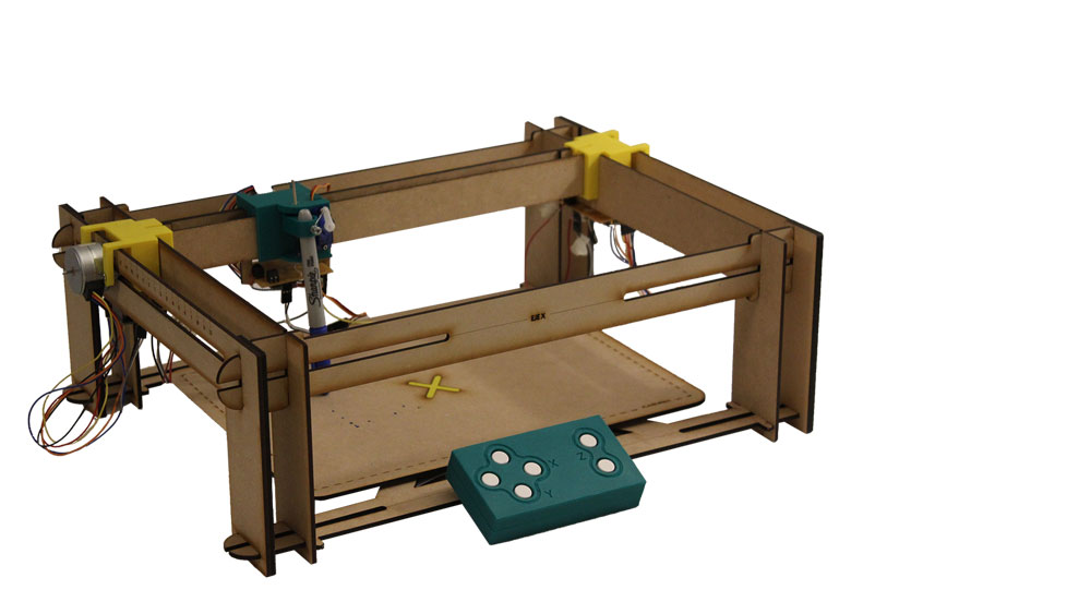
02 build the mechanical parts and operate it manually
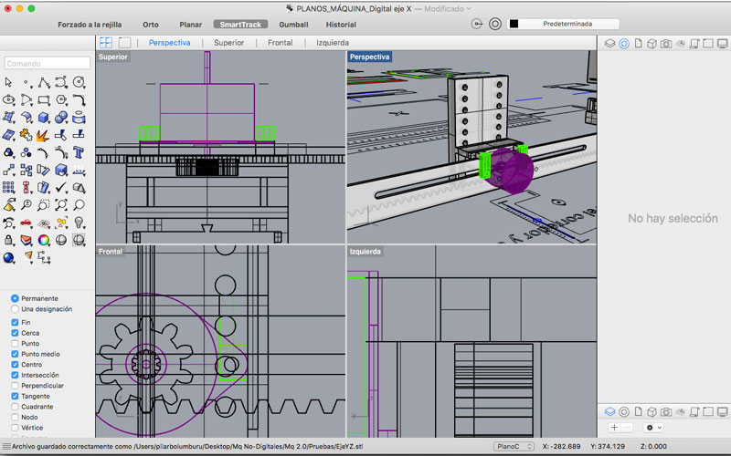
Even the main project of No-Digital Machine is meant to keep analogue; I decide to make 2.0 version. In this version, where you can hack the same machine to be controlled by steppers and aloud kids to manage and understand the machine even more.
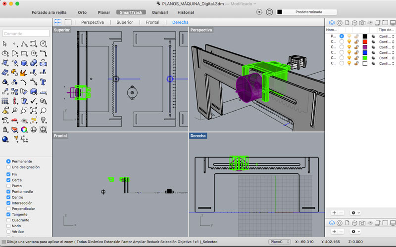
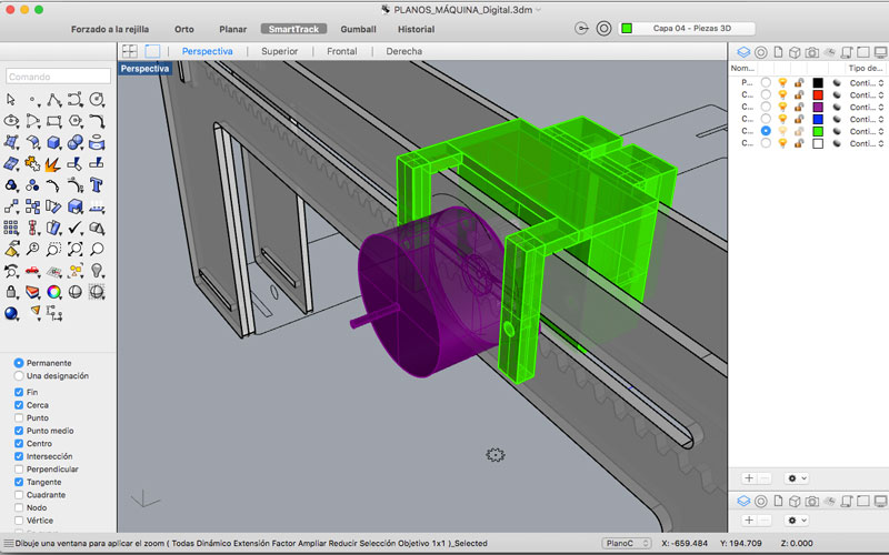
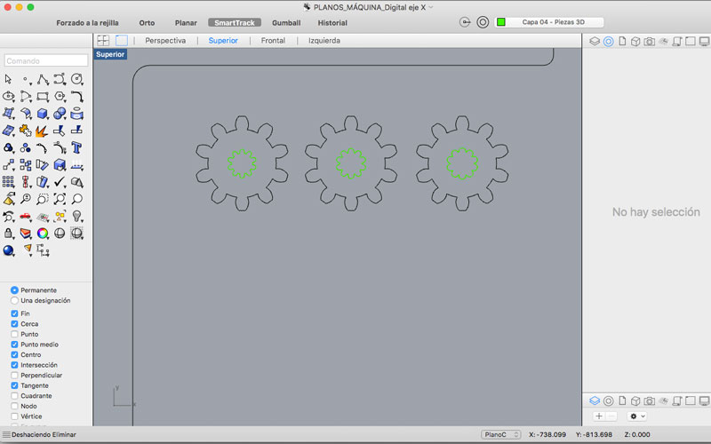
I design all the machine in Rhinoceros, because aloud me to explore different ideas very fast, I can design de 2D and 3D designs and then mix it to observe how the machine is going to assemble.
The ideal for this project will be working in a parametric software, like Fusion 360, so I can adapt it to different weights of materials or change the 3D pieces. But I still a little new in that software, so I am using Rhinoceros now, but for the future development of the project, I will design everything in Fusion.
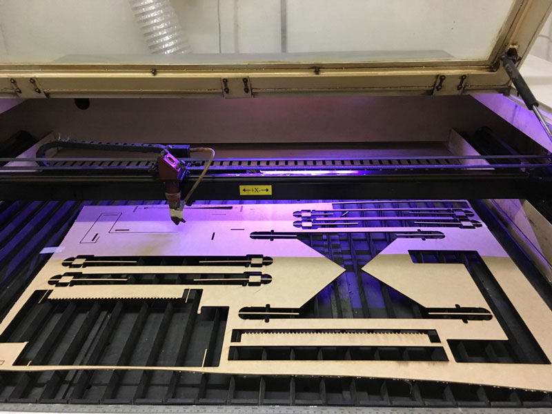
First, I want the machine still be very cheap an easy to fabricate. So I try that most of the framework was on laser cut MDF, some pieces in 3D printing, and inputs/outputs devices.
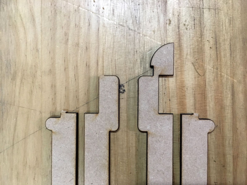
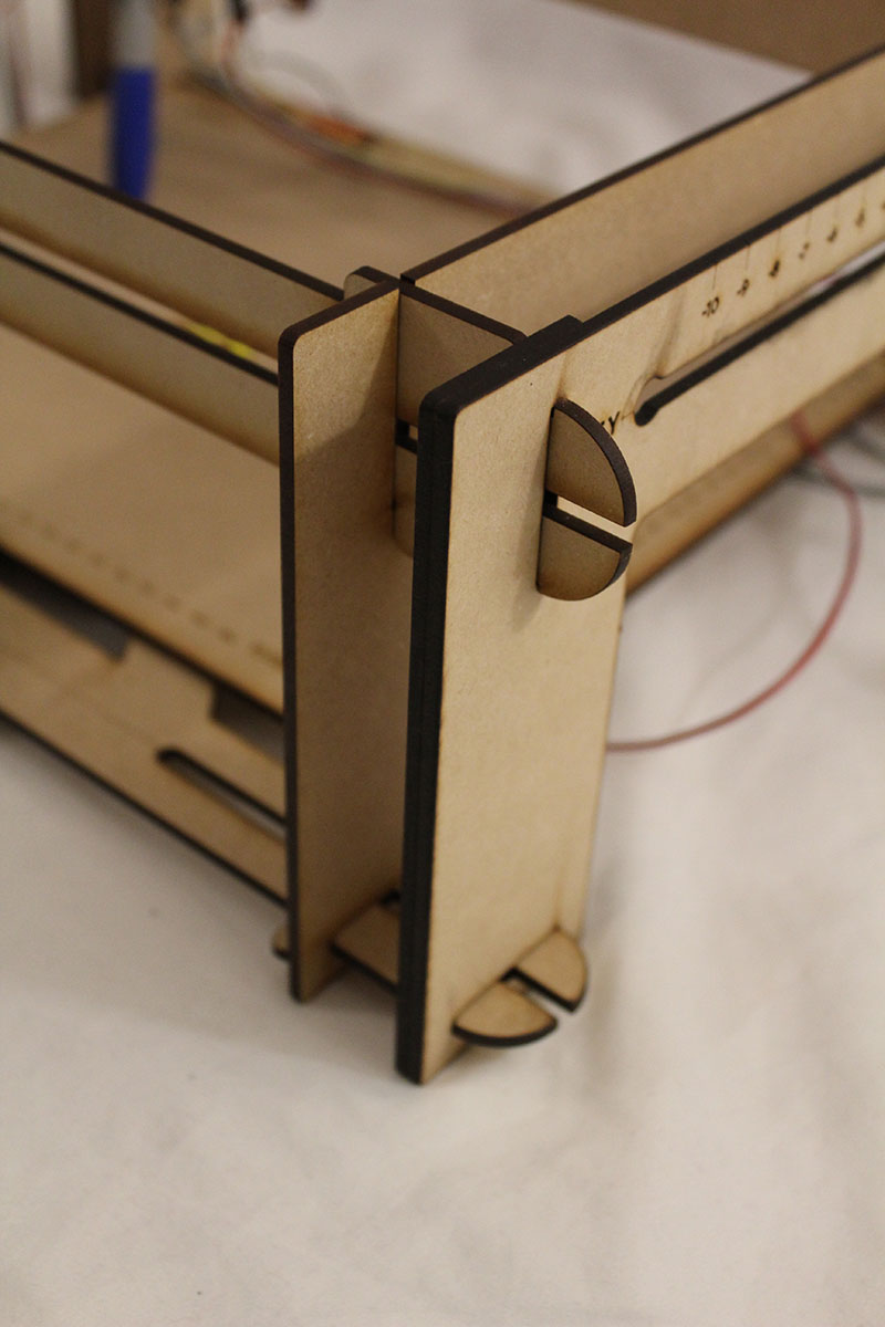
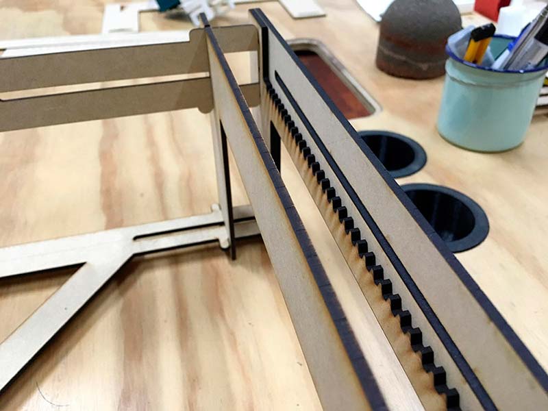
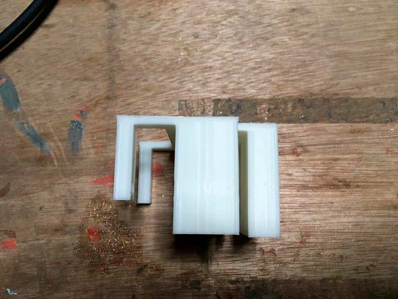
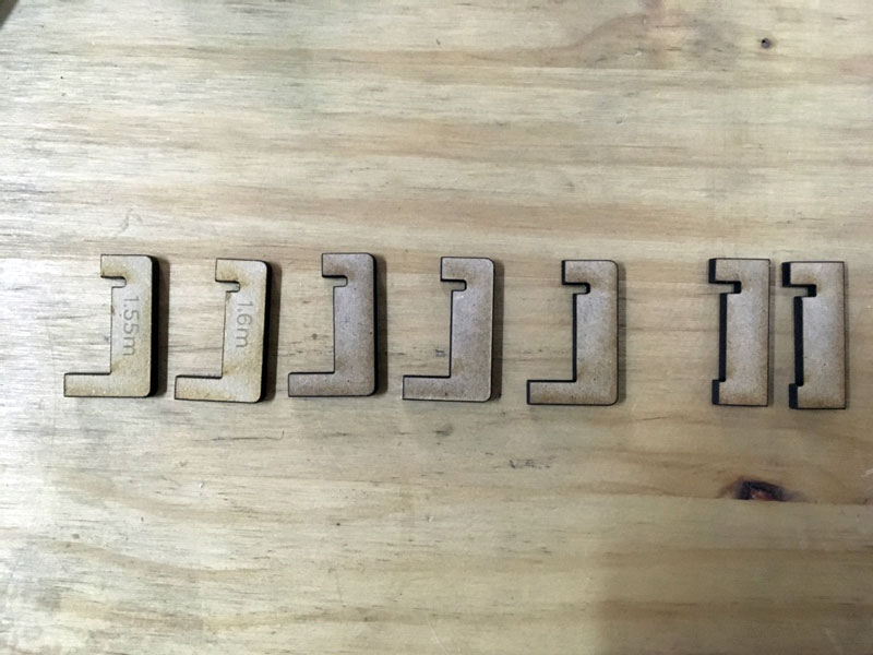
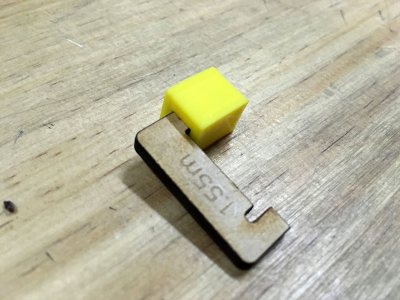
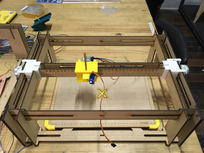
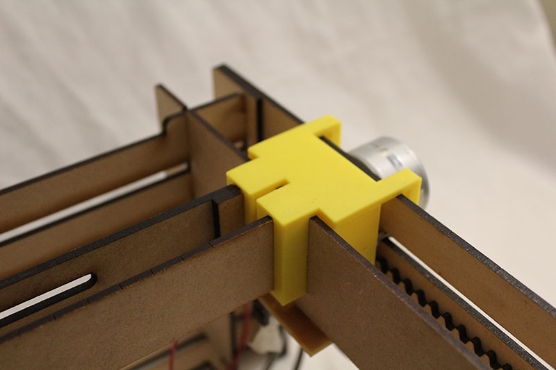
The assembling of the machine is through snaps:
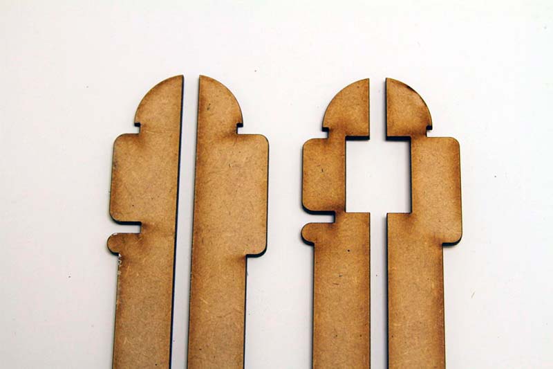
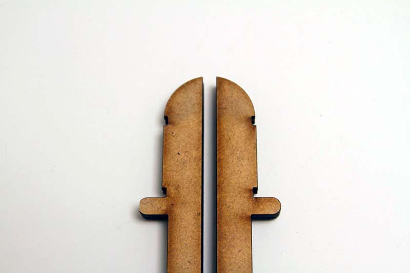
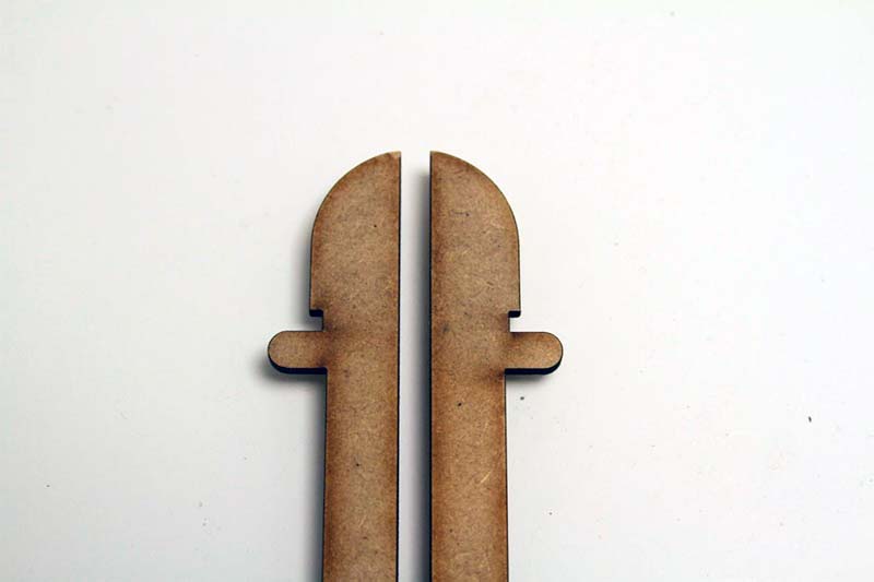
For the final project, I remove the square in the middle of the snap because make it very weak and the broke very often. That works very well.
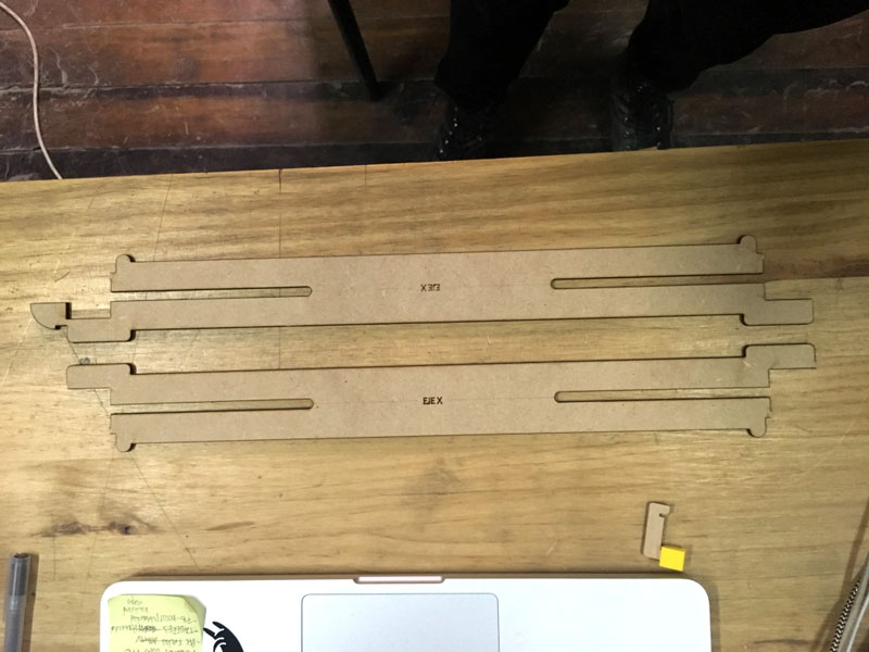
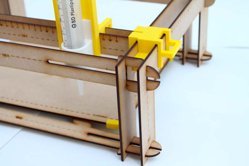
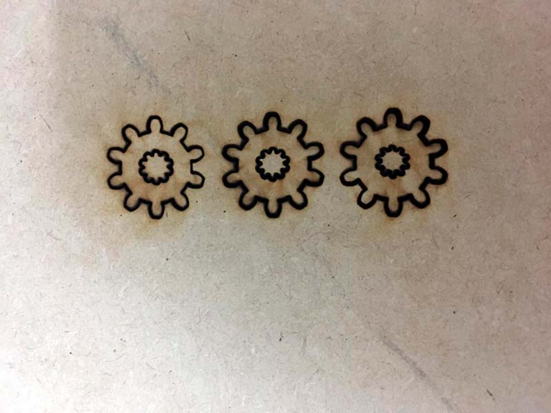
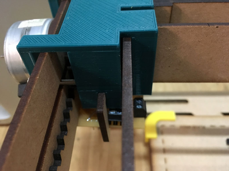
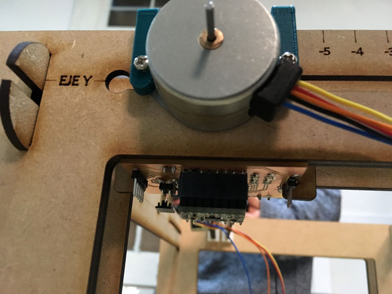
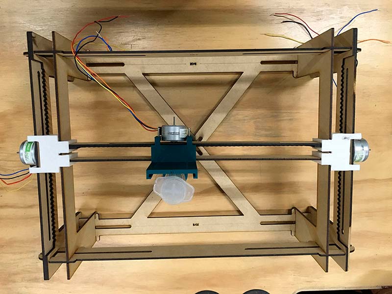
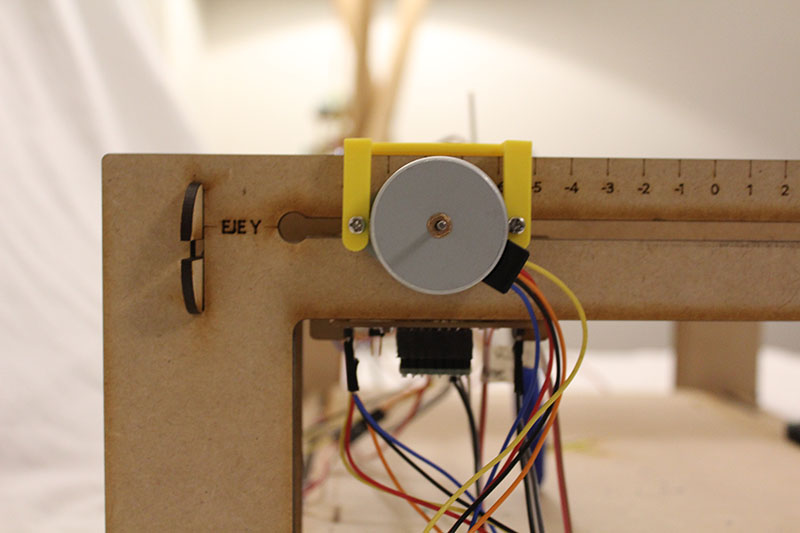
The movement of the X and Y axes is through MDF rack and pinion with a stepper.
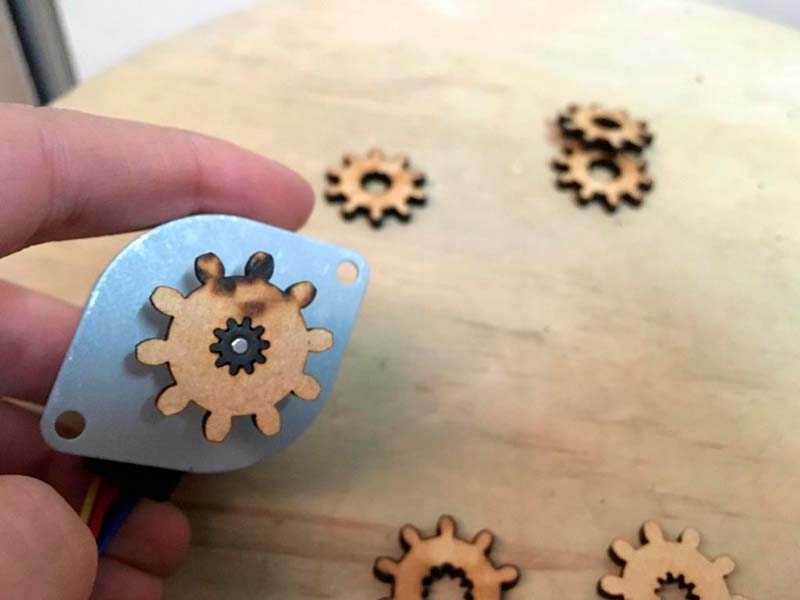
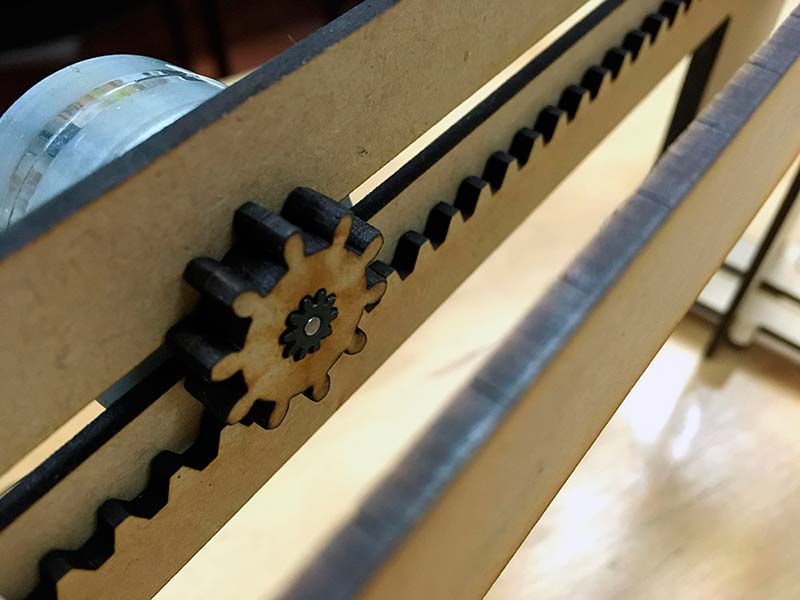
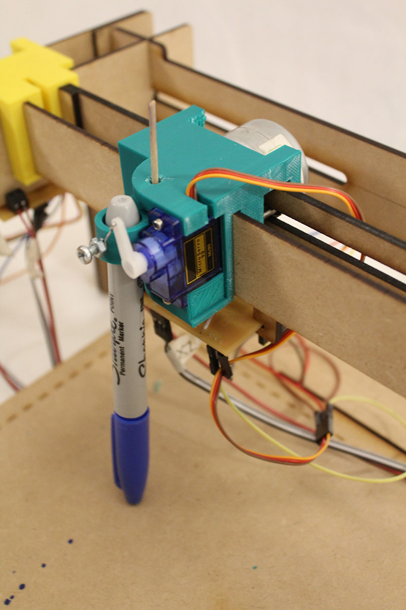
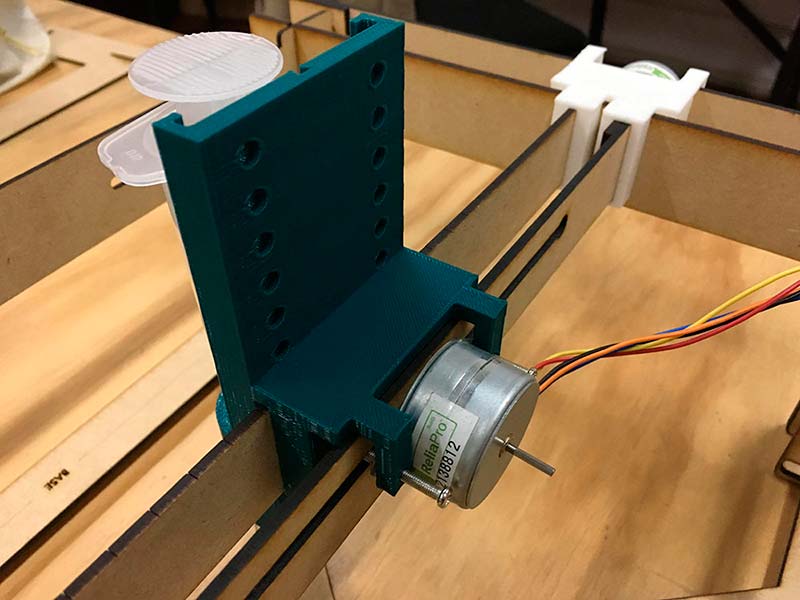
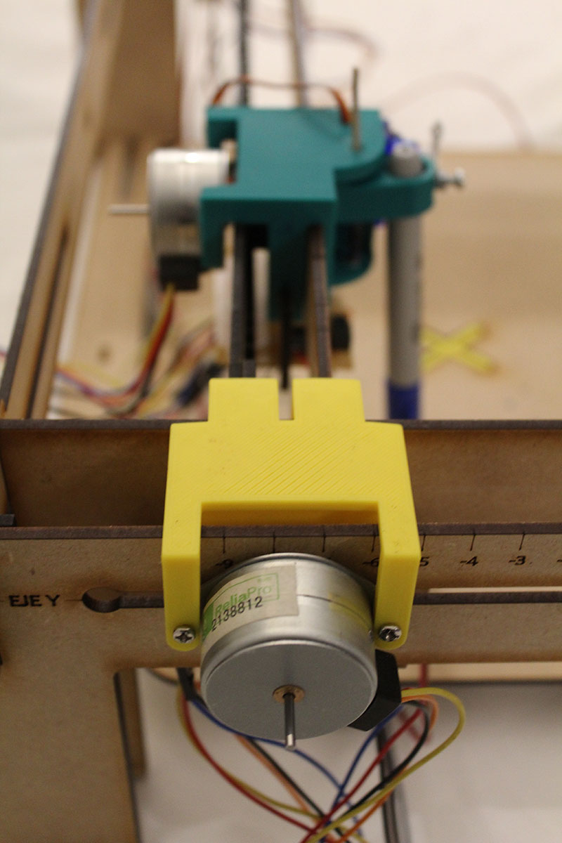
The piece to attach the steppers and move it through the axis is 3D printed in ABS.
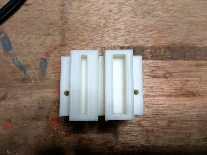
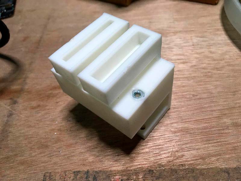
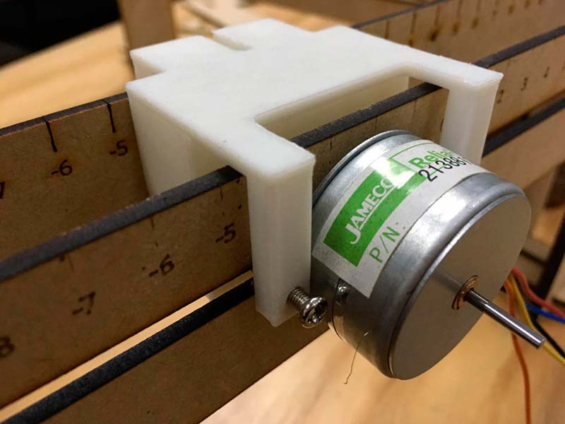
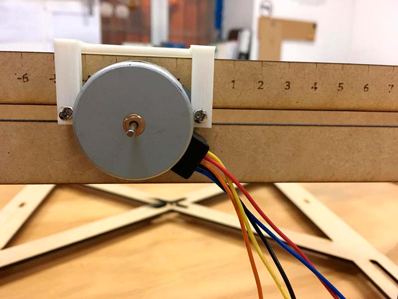
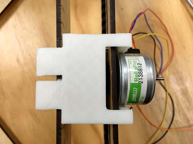
At the final project, the steppers are attached to the piece with nuts and bolts, so the stepper doesn't move. I also add some holes to the sides, to grab some MDF pincers to the sides, so the node boards can be attached at the bottom of the piece.
This works very well, the cons are that still need some adjustments an the wires don't have a place to be saved, but the pros are that can be dismount easily if you want to change something and also the kids can see the boards and understand the logic of how works the machine.
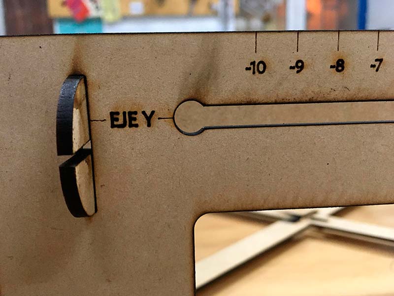
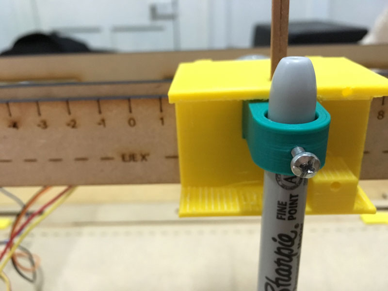
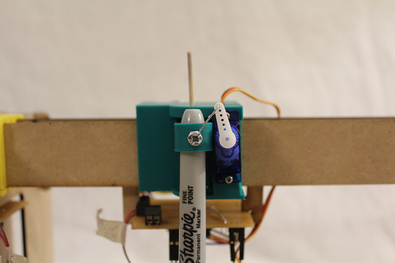
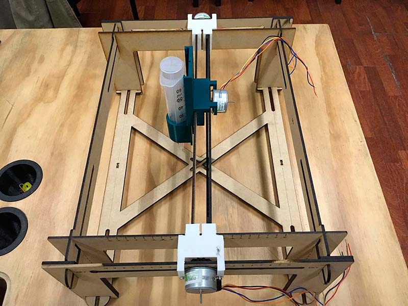
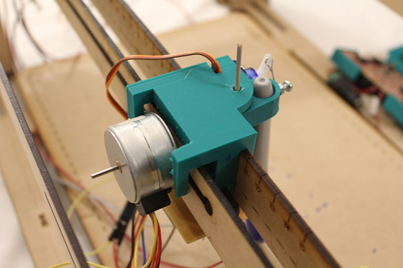
The movement of the Z axis, from the analogue version, were circular steps that you can handle manually and allowed you to change the extruder really easy.
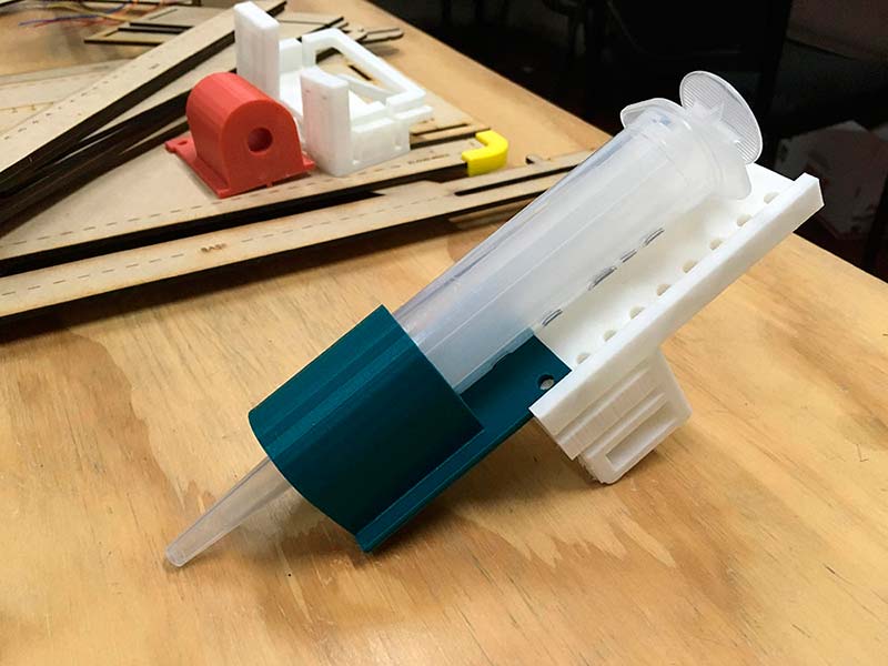
For the final project, I add a micro servo that pushes the piece that attaches a pen to make it draw and I can control it from the main board lowering or raising the pencil.
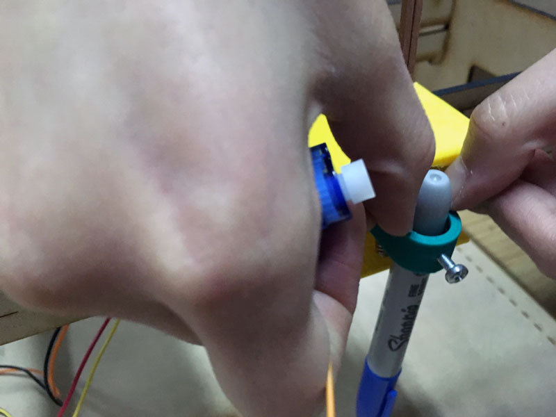
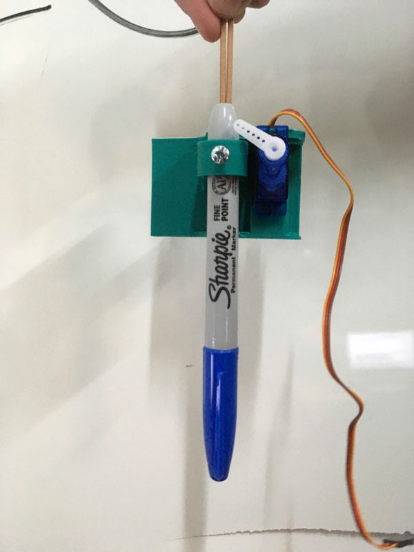
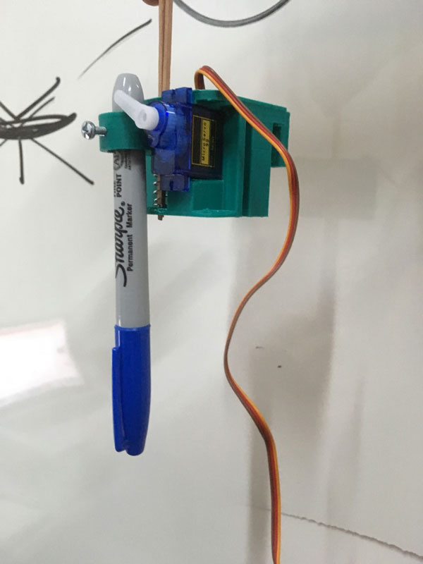
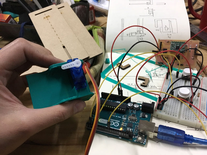
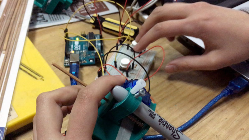
The first idea for the mechanism of this axis was a micro servo that added to a spring levelling the axis. Finally, I decided to use the servo in two movements that are translated through a connecting rod.
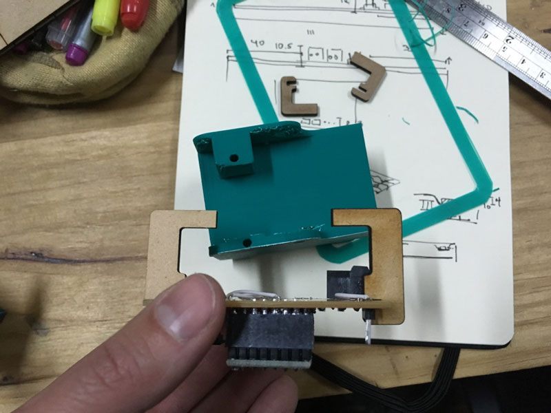
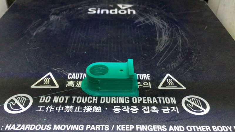
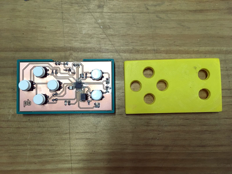
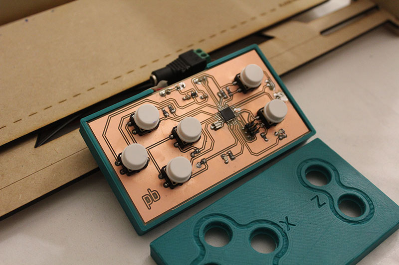
Finally, I design the interface for the main board and the buttons (input). I have some experience designing for electronic, but I am new to designing electronic. So I realize (very late) that I should change the type of pinhead connectors. The pins were too high and at the same level of the buttons, so I have to design an interface that allowed me to press the buttons, but also the components fit the height.
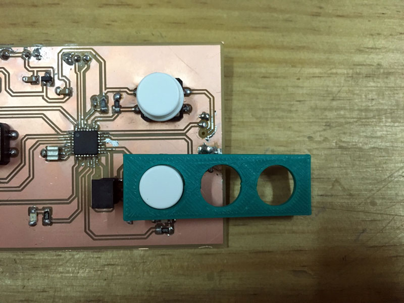
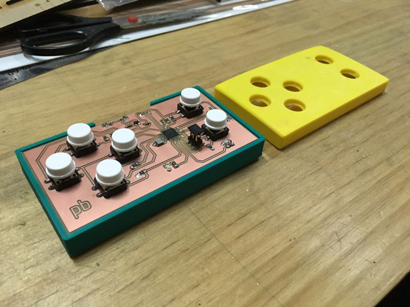
Because I print the interface in ABS with the face down, and when I detach from the bed the colour of the ABS was a little lighter for the separation. I use some thinner to return the colour for the original green.
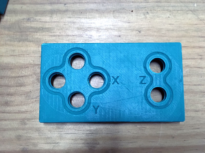
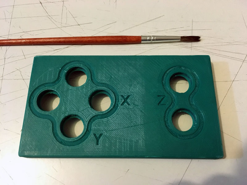
Final button interface:
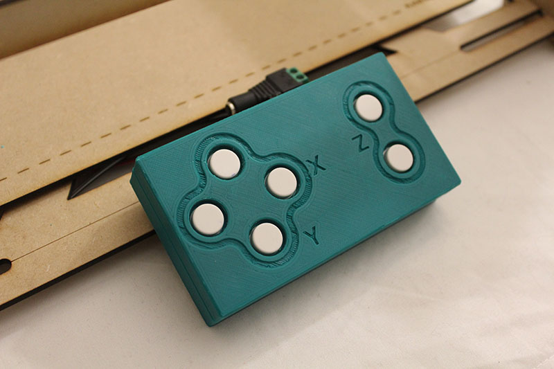
02 build the mechanical parts and operate it manually
Video of machine operate it manually:
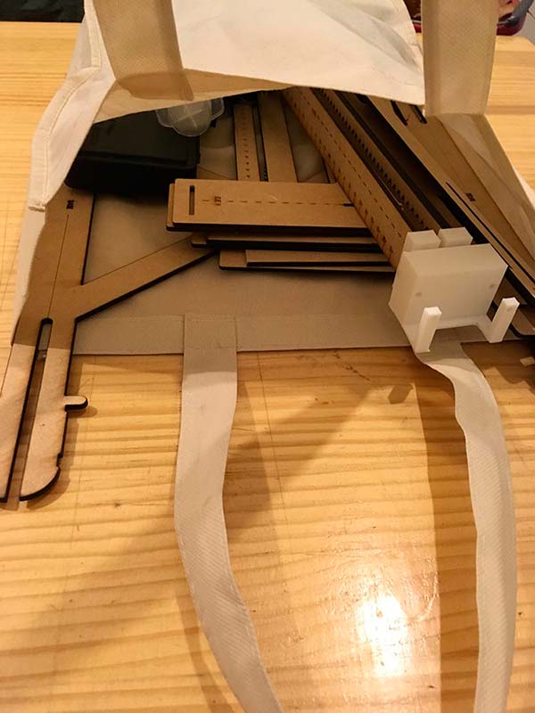
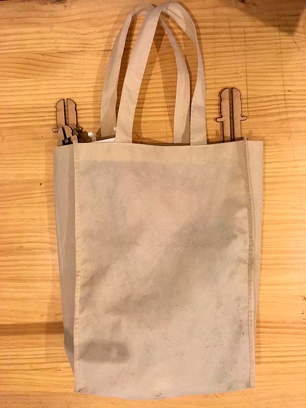
Machine in a bag:
03 actuate and automate your machine
For review the automatization details of the Educational CNC Machine visit my Networking Assignment. All the electronic design & production, and the microcontroller interfacing & programming are in that Assignment.
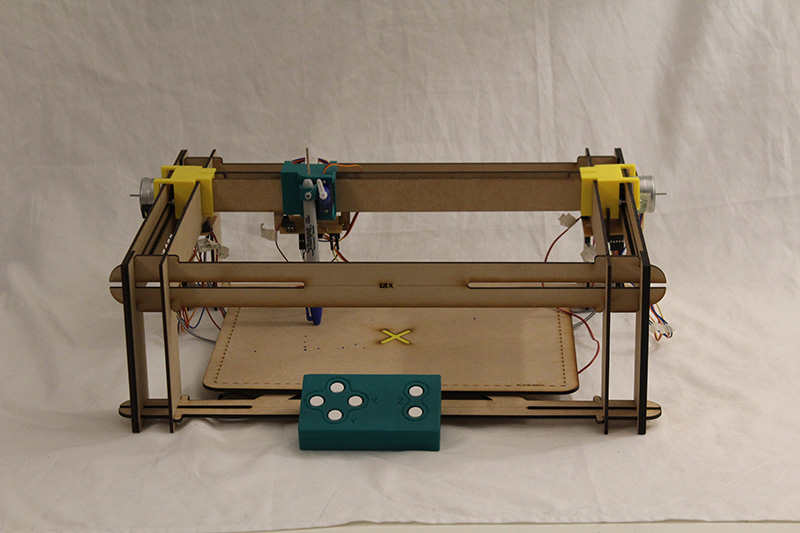
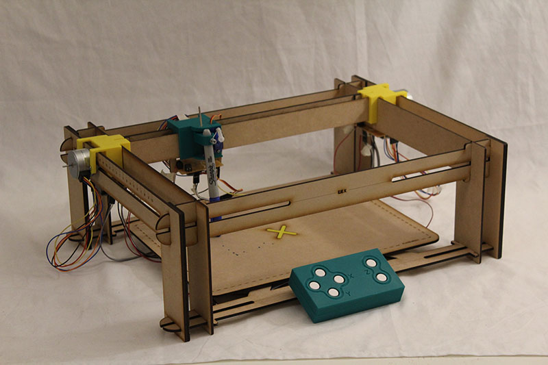
These are the images of the final Educational CNC Machine:
summary video
FAB ACADEMY_EDUCATIONAL CNC MACHINE_PILAR BOLUMBURU from Pilar Bolumburu on Vimeo.
Files
Download Design Fabrication files (2D and 3D)
Download Electronic boards (png and eagle files)
Download Code Main Board Files
Download Code Node Board Files
Even I work these weeks alone, I want to thanks to Javiera Segovia and Stefanía Arías, that had contributed to the development of the "NO-Digital Machine Project" (A project I start developing and is the base of Fab Academy's final project).
Also, I want to thanks to Xavier Gracía, who advise me and guide me in the electronic development and programming of my final project.

Este obra está bajo una licencia de Creative Commons Reconocimiento-NoComercial-CompartirIgual 4.0 Internacional.