Assignment 07_electronic design
01 use the test equipment to observe the operation of a microcontroller circuit board (group)
For this assignment, we have to learn about the equipment that helps us to test our circuit board. The equipment we observe was:
1. Digital voltmeter: Used for measuring the electrical potential difference between two points in an electric circuit, also measure current and resistance.
2. Function generator: Used to generate different types of electrical waveforms over a wide range of frequencies, like a sine wave, square wave, triangular wave and sawtooth shapes
3. Oscilloscope: Allows observation of varying signal voltages.
4. Regulated power supply: To observe signals at electrical level. Used for the measure and compare non-typical voltages or currents
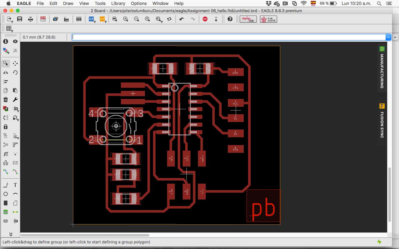
02 redraw the echo hello-world board.
For redraw the echo hello-world board I check the website that was in the lecture, and I base my design on that board.
I redraw the board with Eagle because I like that its compatible with Fusion 360. For the first commands, my instructor helps me to understand the basics of the software.
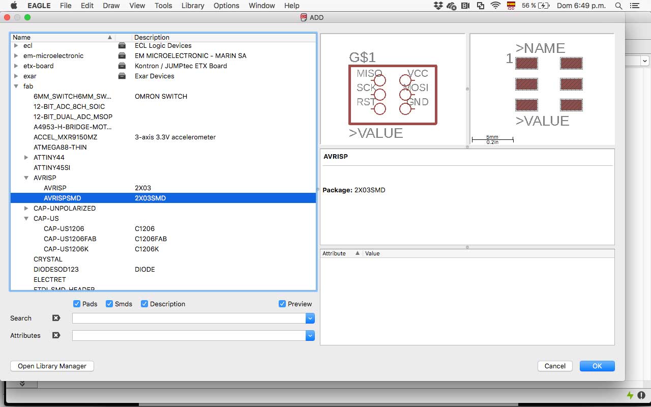
First I create a project and the schematic. Then I download all the Adafruit library–the standard components–and the fab library
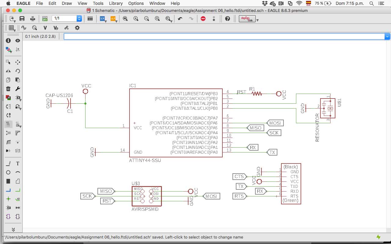
I add all the components of the original board, and then I link it. It was especially helpful the label; they permit to connect elements that are with the same name and is more easy to organize the schema.
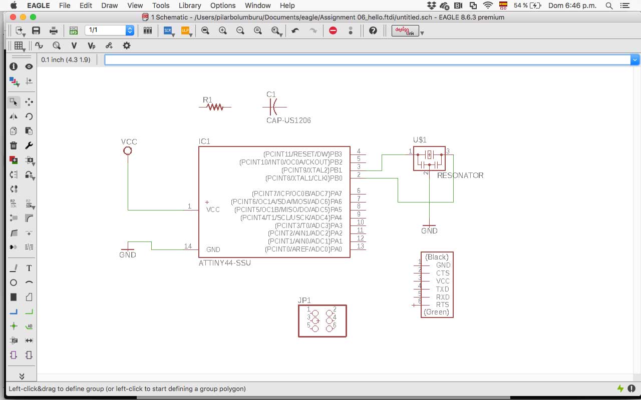
I have to assign values in information to Resistor, Capacitor and Cristal (Resonator), so don’t confuse them later in the board.
I am used to the graphical software, so in the board design, I found the tools a little more basics from which I usually use.Also, I am used to Rhinoceros so It was handy to learn you can just write the commands, not have to search it every time.
03 add (at least) a button and LED (with current-limiting resistors)
For adding the button, I have to research the type of connections that exist and I found about the pull-up button (connected to VCC) and pull down button (connected to GND). I decide for a pull-down button because when is not activated don’t waste energy (like the VCC, even is almost nothing).
Then, for calculating the resistor I search in Sparkfun, and I select a 10k resistor.
To add the led and their resistor I calculate in LedCalc the value of the resistance. The web asks me for Supply Voltage, Voltage Drop Across LED, Desired LED Current, and how many LEDs are connected. The result was that I need it a resistance of 680Ohm, but I finally use one of 499Ohm (you can also say 499R) because was the one we had in the fab lab and was enough to don’t burn the led.
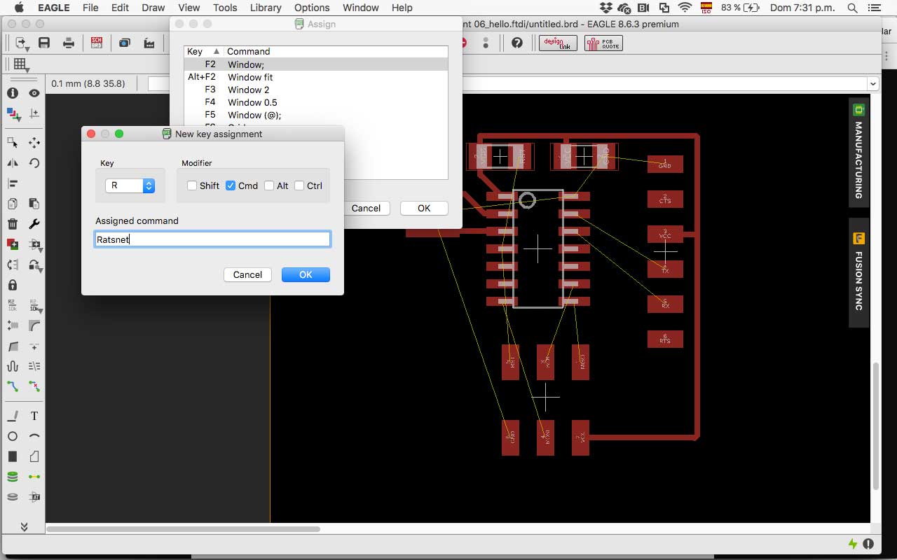
I also set a shortcut for Rastnest to be easier to check the connections between the components.
04 check de design rulers, make it and test it
CHECK
When I end the schematic, I run the ERC to correct the connections. Los mistakes were:
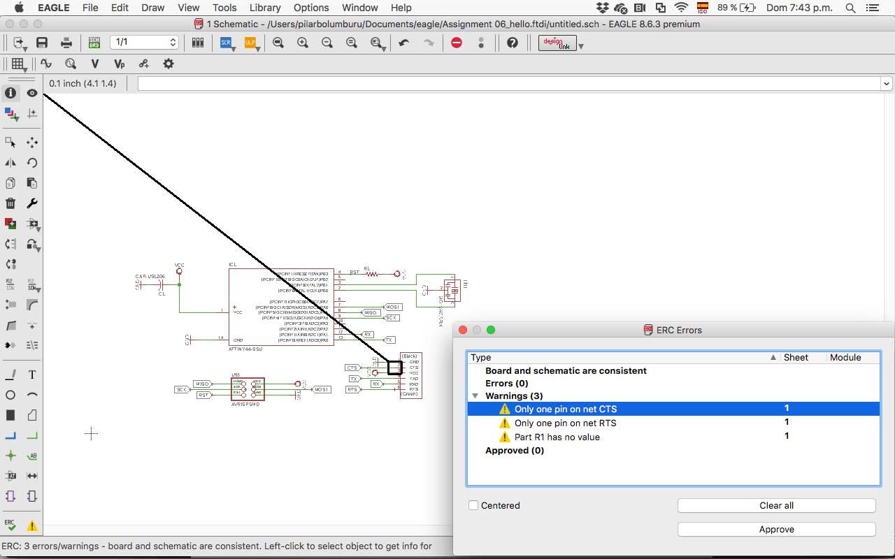
- Only one pin on net CTS
- Only one pin on net RTS
- Part R1 has no value
I add the value for R1 (10k) and the Capacitor (1uF) and approve the other errors that don't affect in the fabrication.
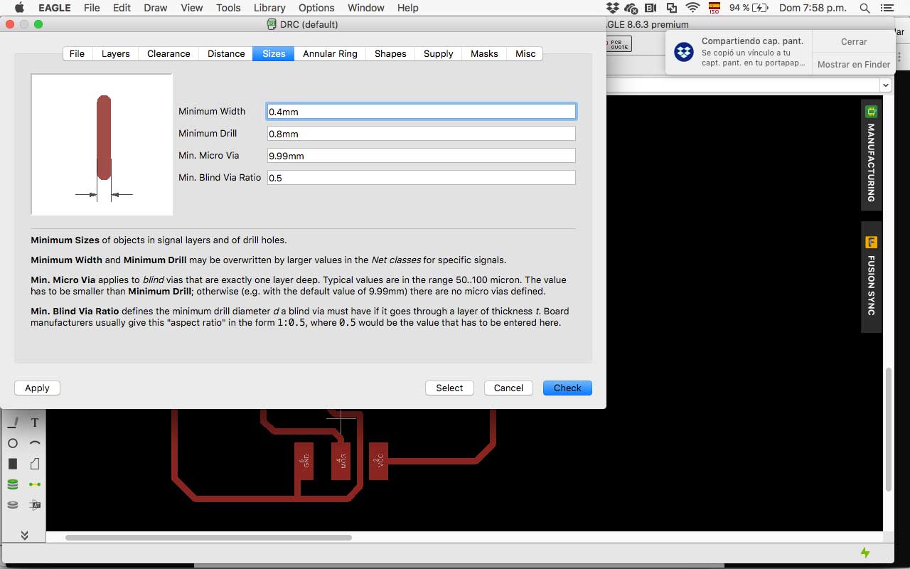
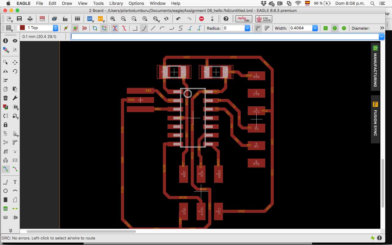
When I end organizing the elements on the board, I change the width of the traces for the 1/64 mill (0,4mm) and draw the connections between them. Then, I set the DRC for the end mill.
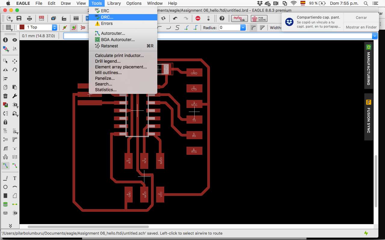
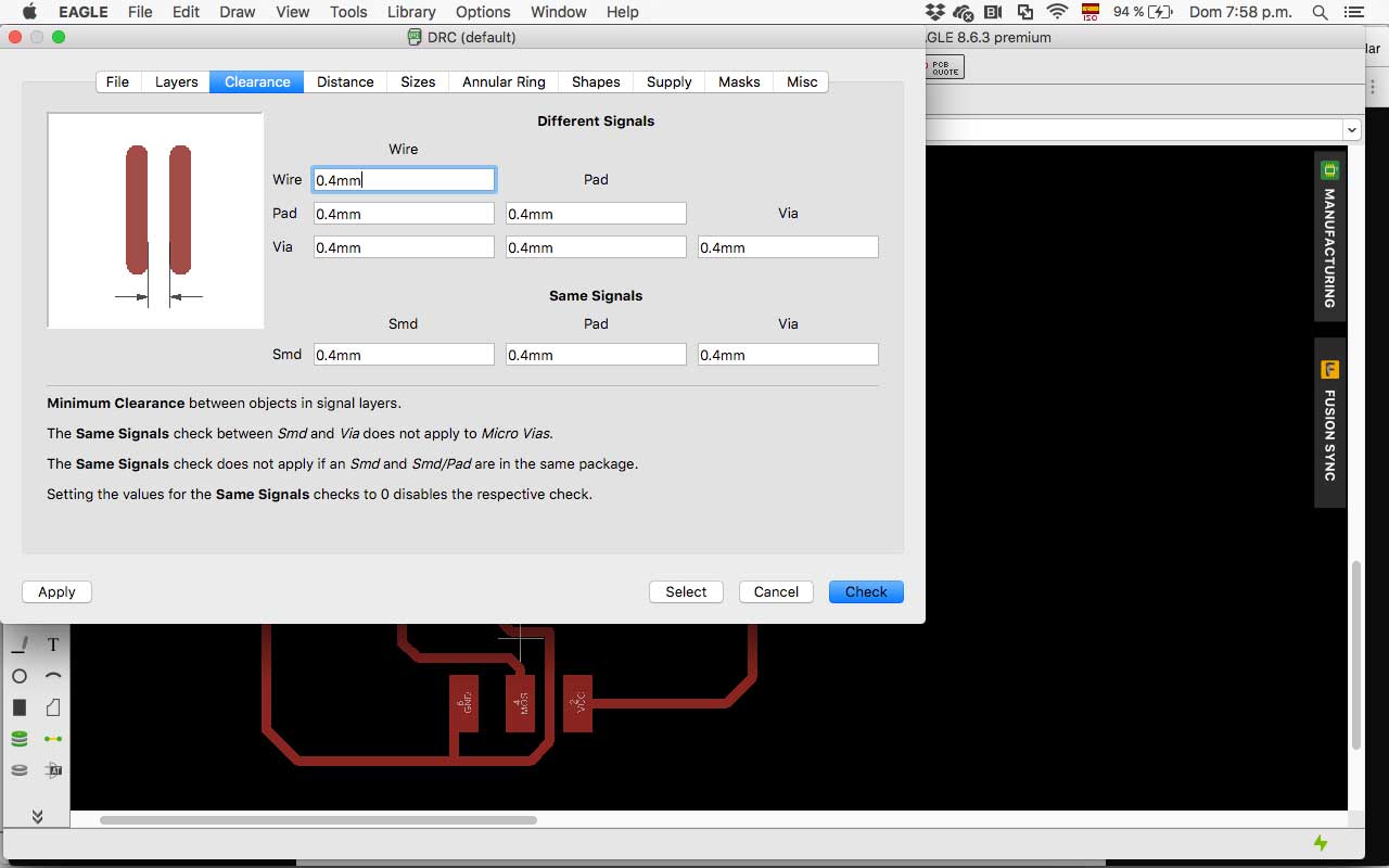
After that I run it analyzing if its correct for fabrication. The results were:
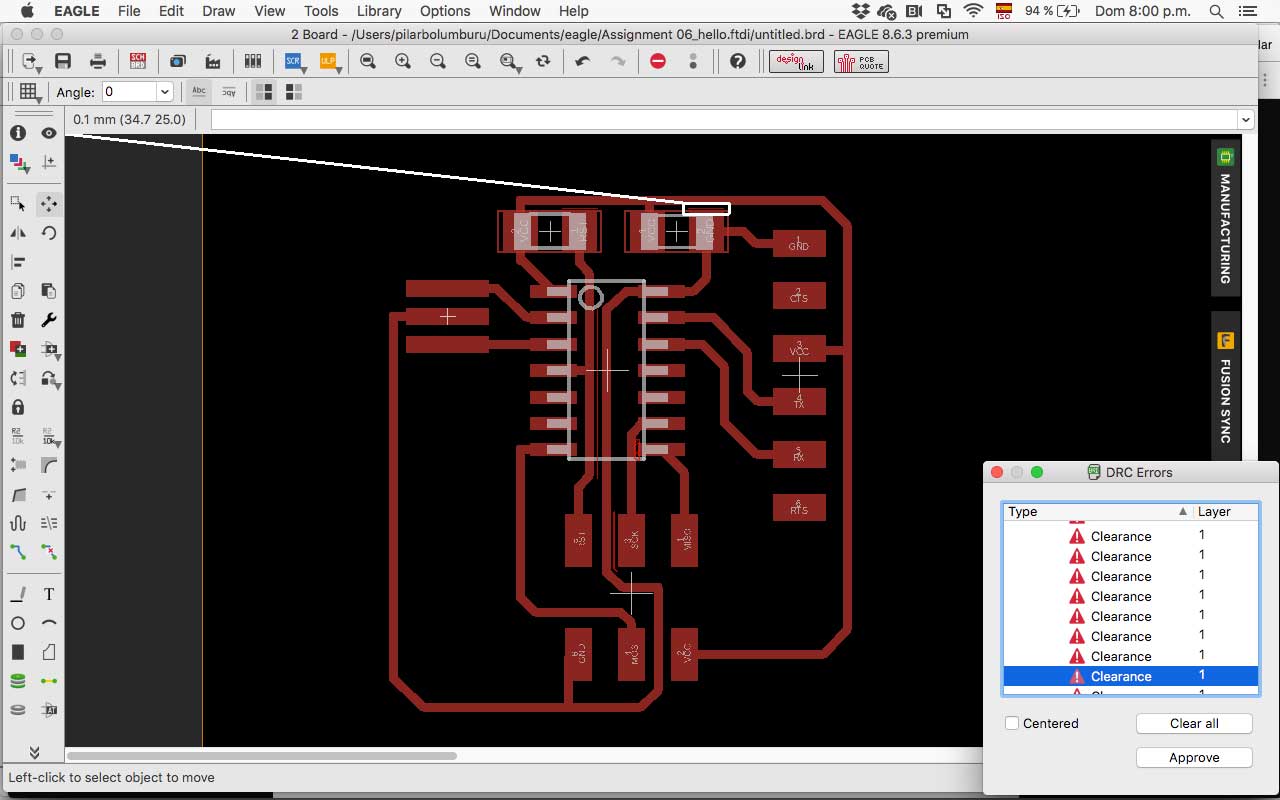
- Very thin difference between the upper trace and the R1 and C1
- very thin difference between GND trace in the middle of the attiny and the other traces
Then I correct the distance between the traces and the components.
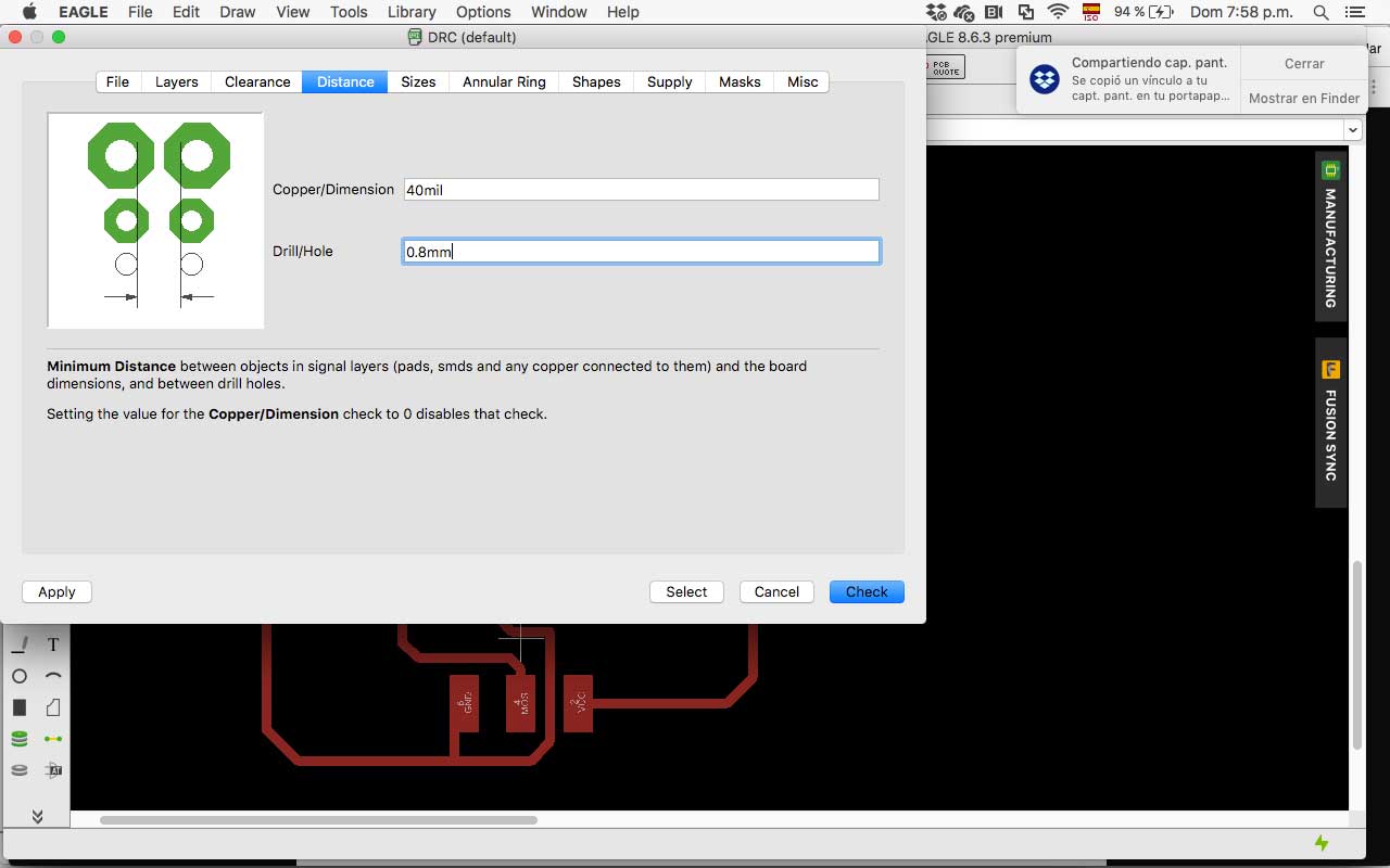
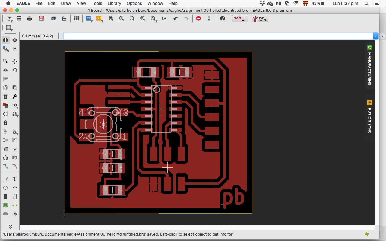
Finally, I create a ground plane on the board for optimizing the time of machining and rerun the DRC. I choose and offset of 0.8mm from the components and trace to avoid mistakes.
MAKE IT
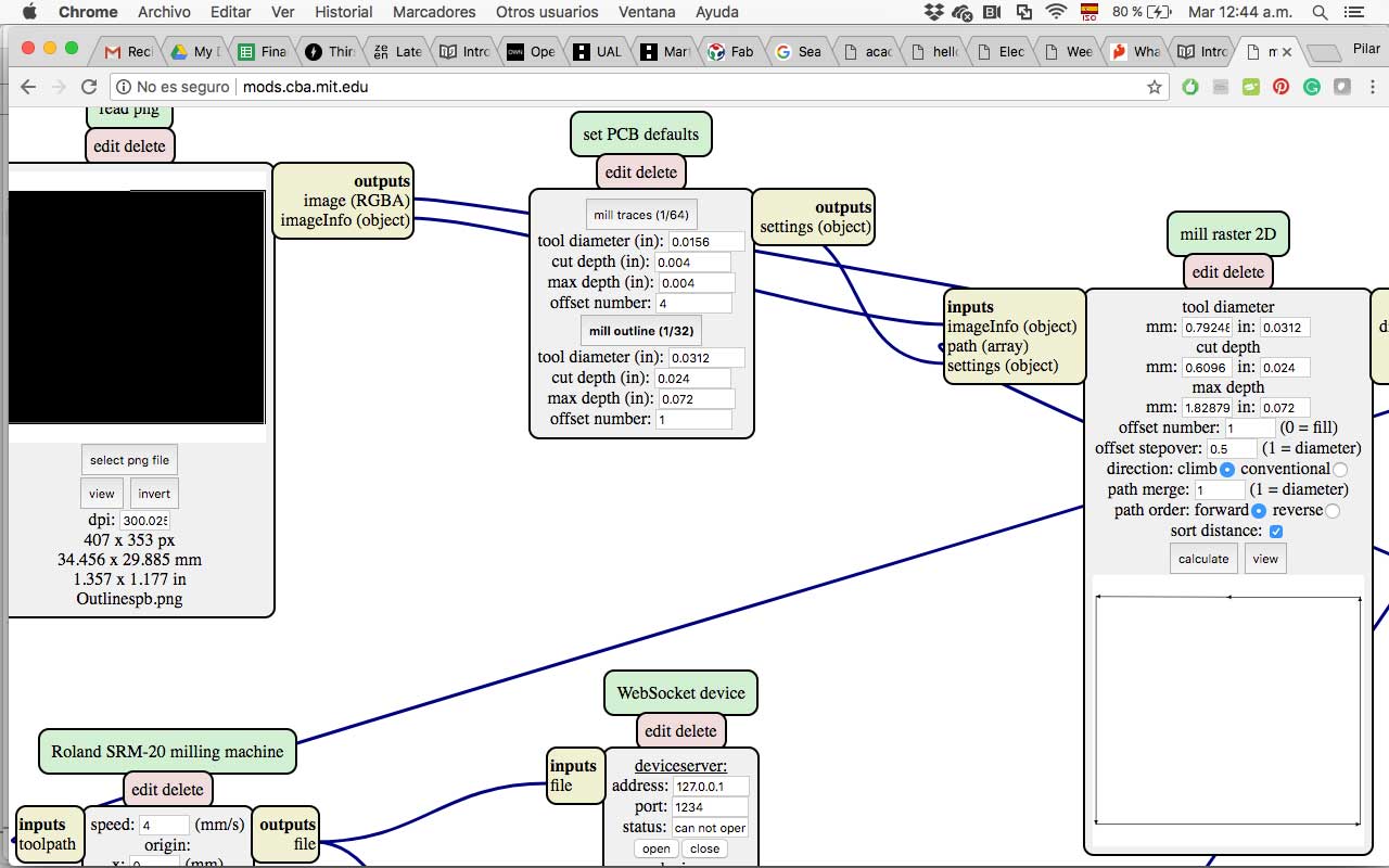
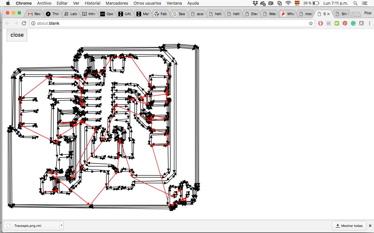
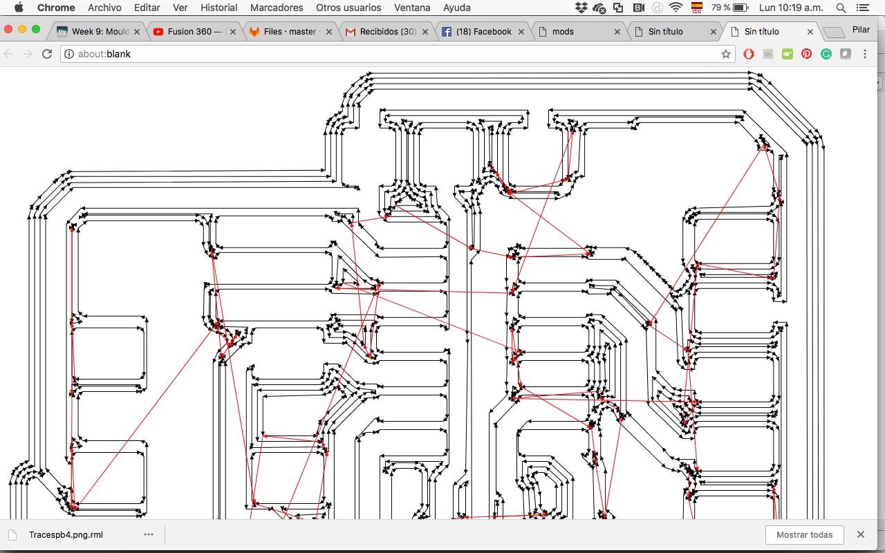
After check the design rules with ERC (schematic) and DRC (board), I export the traces and outline files on png for uploading to mods. In Mods, I generate the files to monoFab SRM-20.
First I exported the png in 300 resolutions but wasn't enough, and the traces file was wrong when I calculated in mods, and some traces were miss. So I re-export it in 1000 resolution and recalculate in mods. This file was correct.
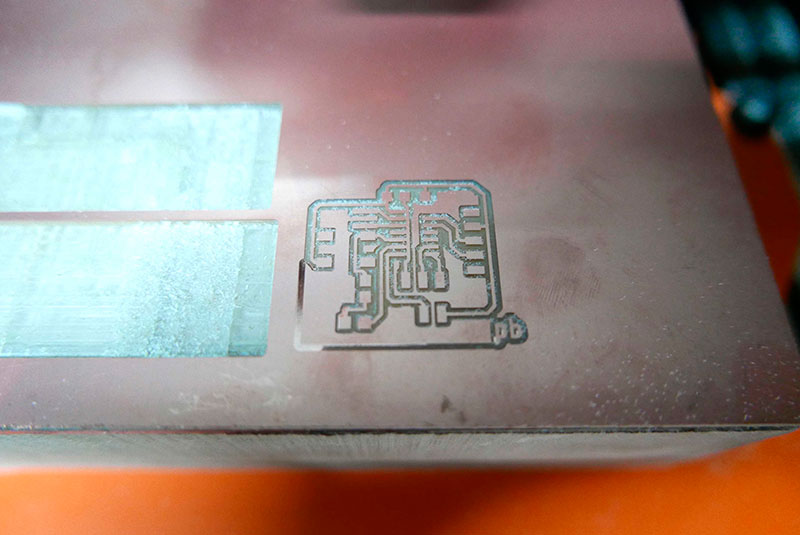
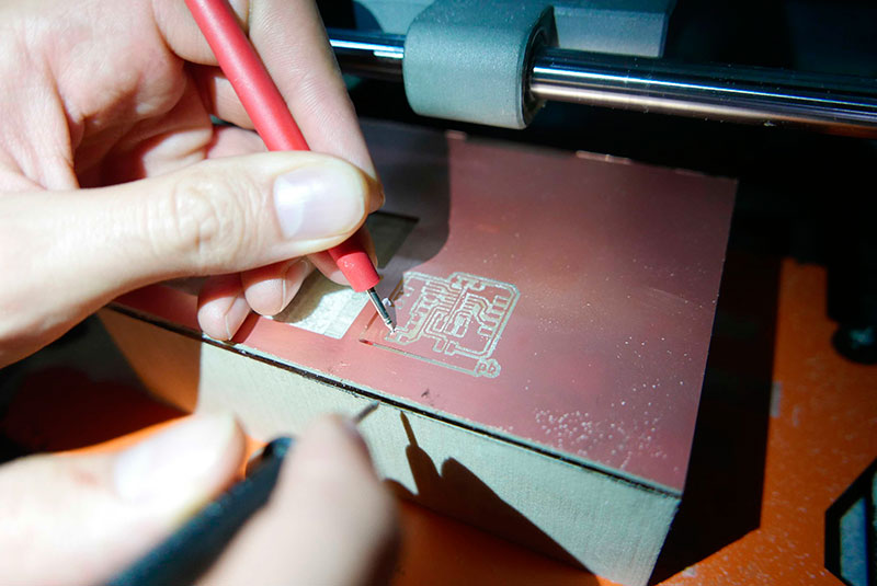
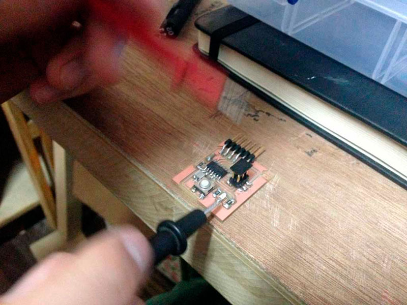
I fabricate the trails, but at the first try one side wasn't well cut, so I test it with the multimeter, and It was necessary to retrace the board. So I change the zero of Z axis and then rerun it correctly.
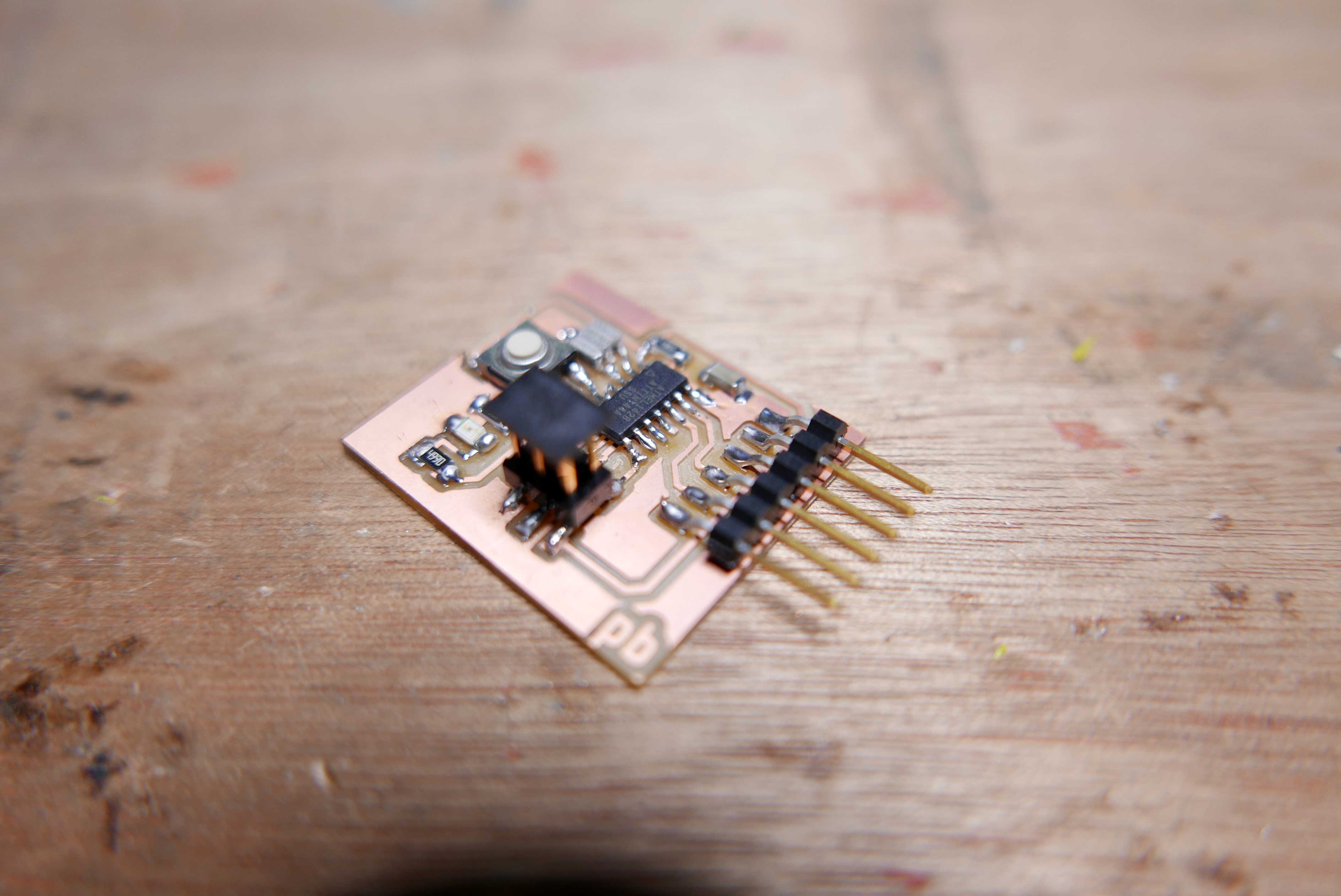
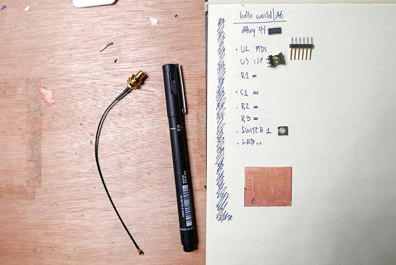
Then I recollect all the components for the board:
- A44= Attiny 44
- U2= FTDI
- U3= ISP
- R1= Resistor 10k
- C1= Capacitor 1uF
- R2= Resistor 10k
- R3= Resistor 499Ohm
- Switch 1= Button
- LED= Green led
- XTAL= Resonator
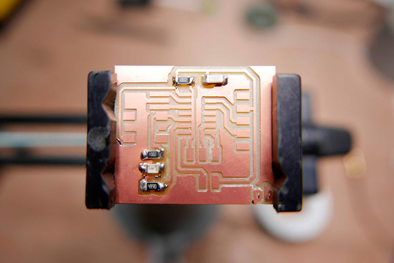
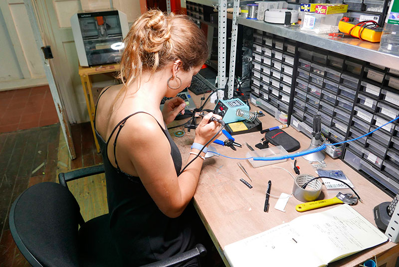
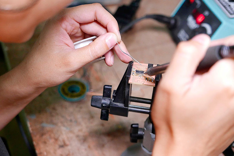
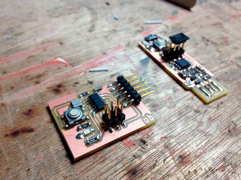
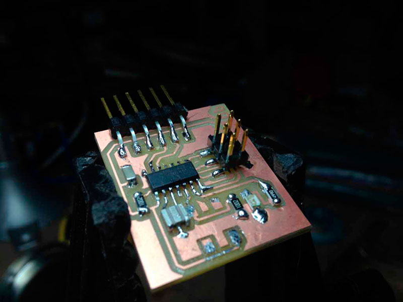
I start the soldering the more little elements like the resistors, capacitors and the led. After that, I solder the ISP because later the Attiny will obstruct me. Then I solder the Attiny44, the crystal, the button and, in the end, the FTDI.
TEST IT
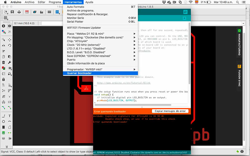
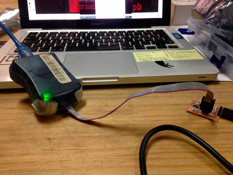
For programming my board I have some problems when I connect it to the computer, the led went on, but that doesn't suppose to happen. Then I try to load the program, but I couldn't do it. I am still figuring what happen, I observe the solder but looks good.
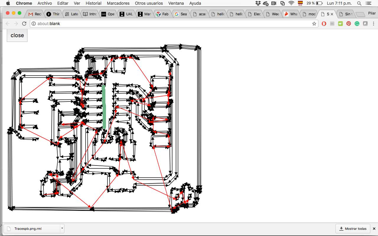
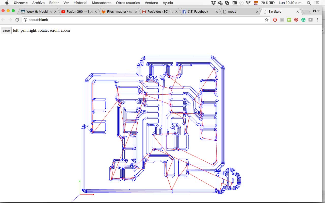
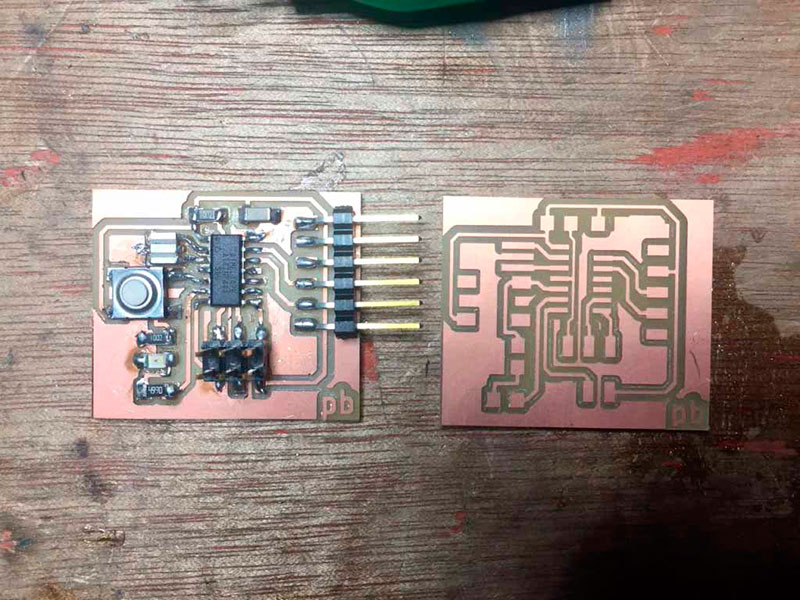
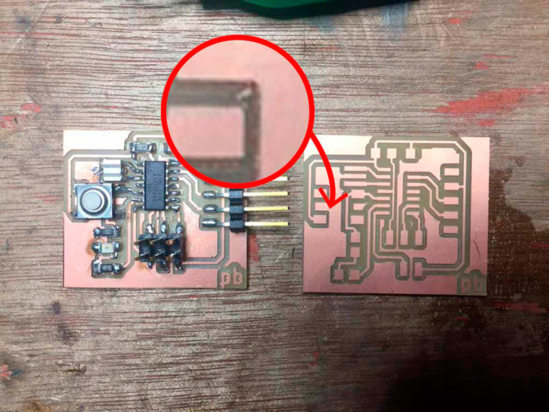
I use the multimeter, and I found that all the left pins of the Attiny where connected, that wasn’t supposed to work like that. So I review the traces file generated in mods and I realize that there was an error with mods and didn’t create the trace where the pins end.
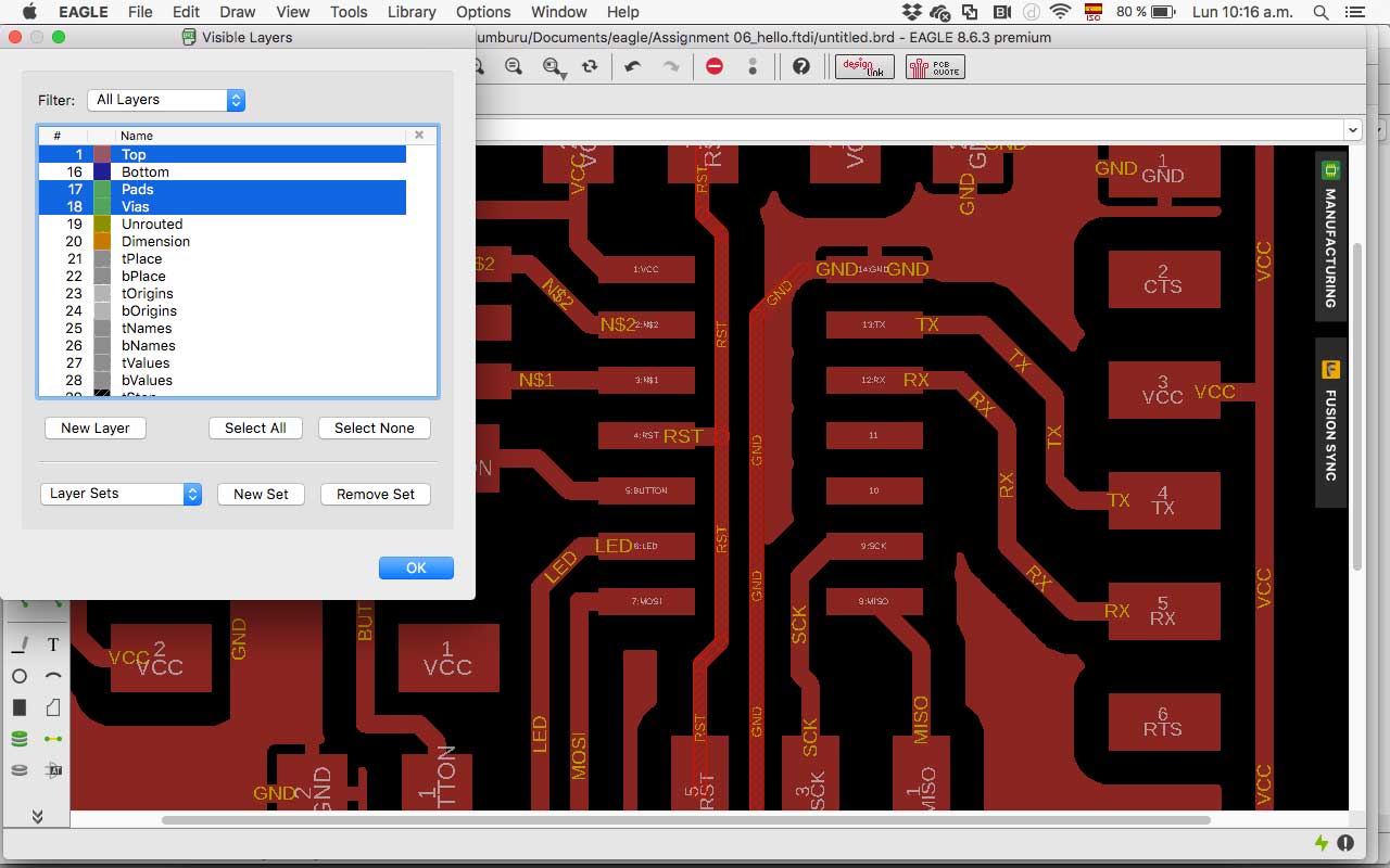
The next pictures show the difference, the left image is the wrong file (show it with the green line) and the right one is the new one.
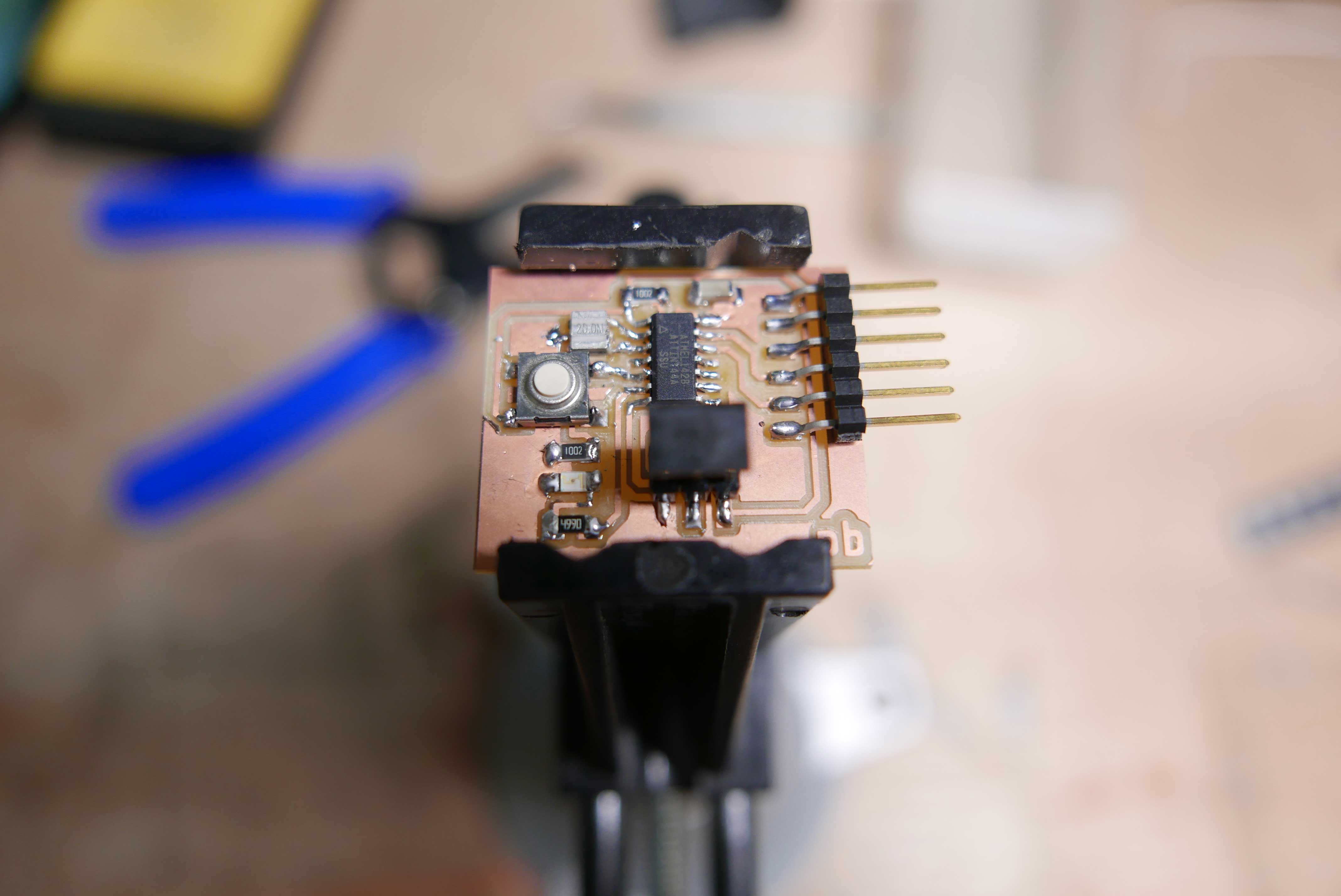
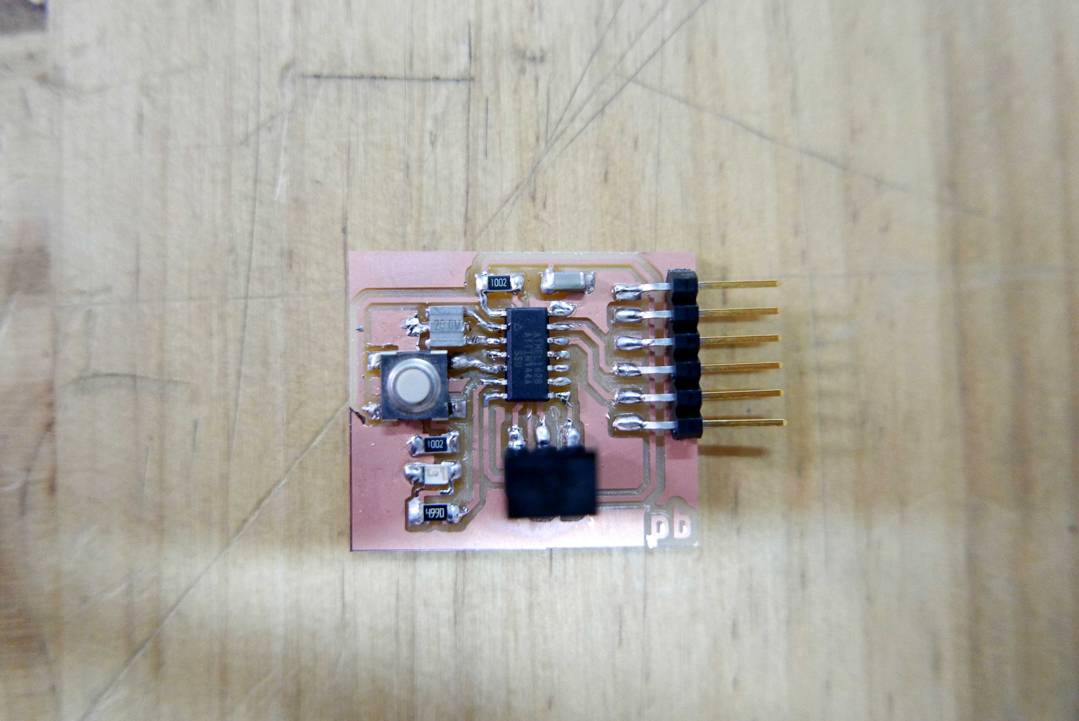
I fabricate my board again, and I sold it again.
I try to load a program on the board and again have a problem. I verify the PCB with the multimeter, and I found two problems:
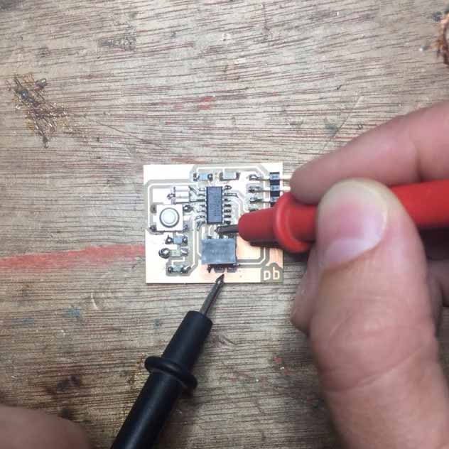
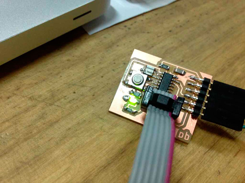
- One of the ISP wasn’t well sold, so I fix it.
- Somehow, the VCC was connected with the GWD; I didn’t know where..but I start searching, and everything looks well. I re-check the images of the board before I sold the components and I saw a little waste that could be the problem, so I desolder the button and I clean the residue. The I use the multimeter again, and the problem was fixed. Finally, I had my board working!!
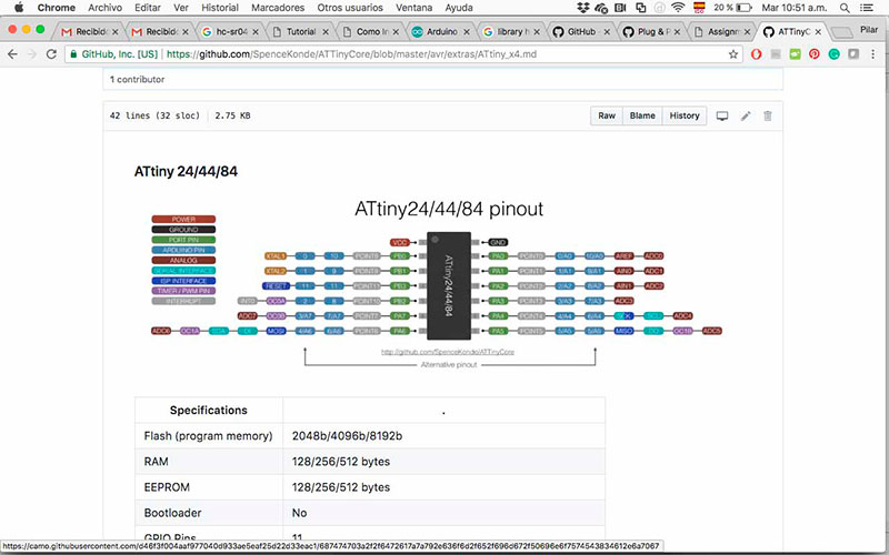
I Burn the bootloader to the PCB, selecting the ATtiny 44 and choosing the external clock of 22 MHz. I load the example of blink from Arduino, searching which pin was the one from the led. The led works!
Download PCB Fabrication Files

Este obra está bajo una licencia de Creative Commons Reconocimiento-NoComercial-CompartirIgual 4.0 Internacional.