Week 8: Embedded Programming
This week we have to reed the datasheet of the microcontroller which we use for programming. I have choosen ATmega328p-PU for this assignement. Later we have to programm the Hello World Board.
ATmega 328p-AU Data Sheet
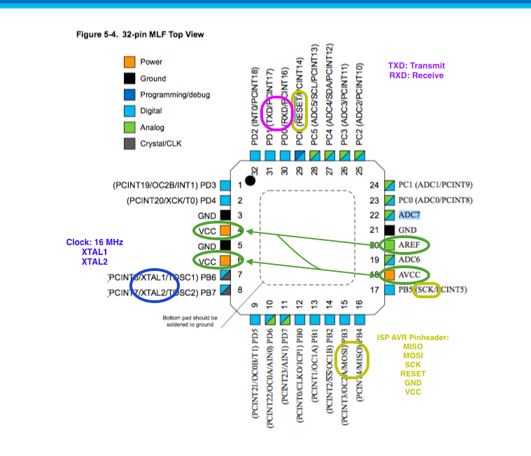
ATmega 328p-AU Pinout from Atmel Data Sheet
In the image above I taged the most important pins of ATmega328p-AU. In the folowing I will describe the fuction of those pins:
All Voltage supply Pins have to be connected.
From the Data Sheet ATmega328p-AU:
VCC
Digital supply voltage.
GND: Ground.
AVCC:
AVCC is the supply voltage pin for the A/D Converter, PC[3:0], and PE[3:2]. It should be externally connected to VCC, even if the ADC is not used. If the ADC is used, it should be connected to VCC through a low-pass filter. Note that PC[6:4] use digital supply voltage, VCC.
AREF
AREF is the analog reference pin for the A/D Converter. 5.2.9. ADC[7:6] (TQFP and VFQFN Package Only)
In the TQFP and VFQFN package, ADC[7:6] serve as analog inputs to the A/D converter. These pins are powered from the analog supply and serve as 10-bit ADC channels.
RESET (PC6):
If the RSTDISBL Fuse is programmed, PC6 is used as an I/O pin. Note that the electrical characteristics of PC6 differ from those of the other pins of Port C. If the RSTDISBL Fuse is unprogrammed, PC6 is used as a Reset input. A low level on this pin for longer than the minimum pulse length will generate a Reset, even if the clock is not running. Shorter pulses are not guaranteed to generate a Reset. The various special features of Port C are elaborated in the Alternate Functions of Port C section.
XTAL1/XTAL2 (Port B): Port B is an 8-bit bi-directional I/O port with internal pull-up resistors (selected for each bit). The Port B output buffers have symmetrical drive characteristics with both high sink and source capability. As inputs, Port B pins that are externally pulled low will source current if the pull-up resistors are activated. The Port B pins are tri-stated when a reset condition becomes active, even if the clock is not running. Depending on the clock selection fuse settings, PB6 can be used as input to the inverting Oscillator amplifier and input to the internal clock operating circuit.
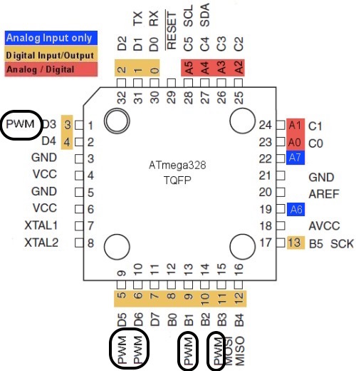
Folowing image shows the spread of the PWM-Pins, digital and analog pins of ATmega328p-AU. PWM (Pulse Width Modulation) pins are important for the control of analog devices such as RGB LED or for transfer of sensing data over long distances. Using PWM we can also regulate the intensity of the light and control of DC motors.
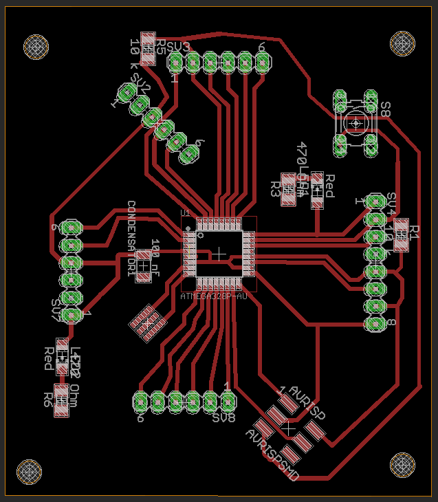
My ATmega328p Board final Layout:
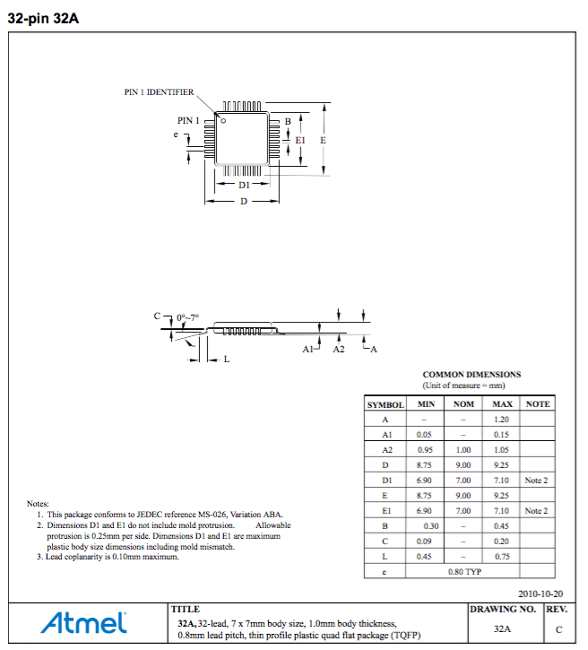
Atmega 328p-AU Dimensions
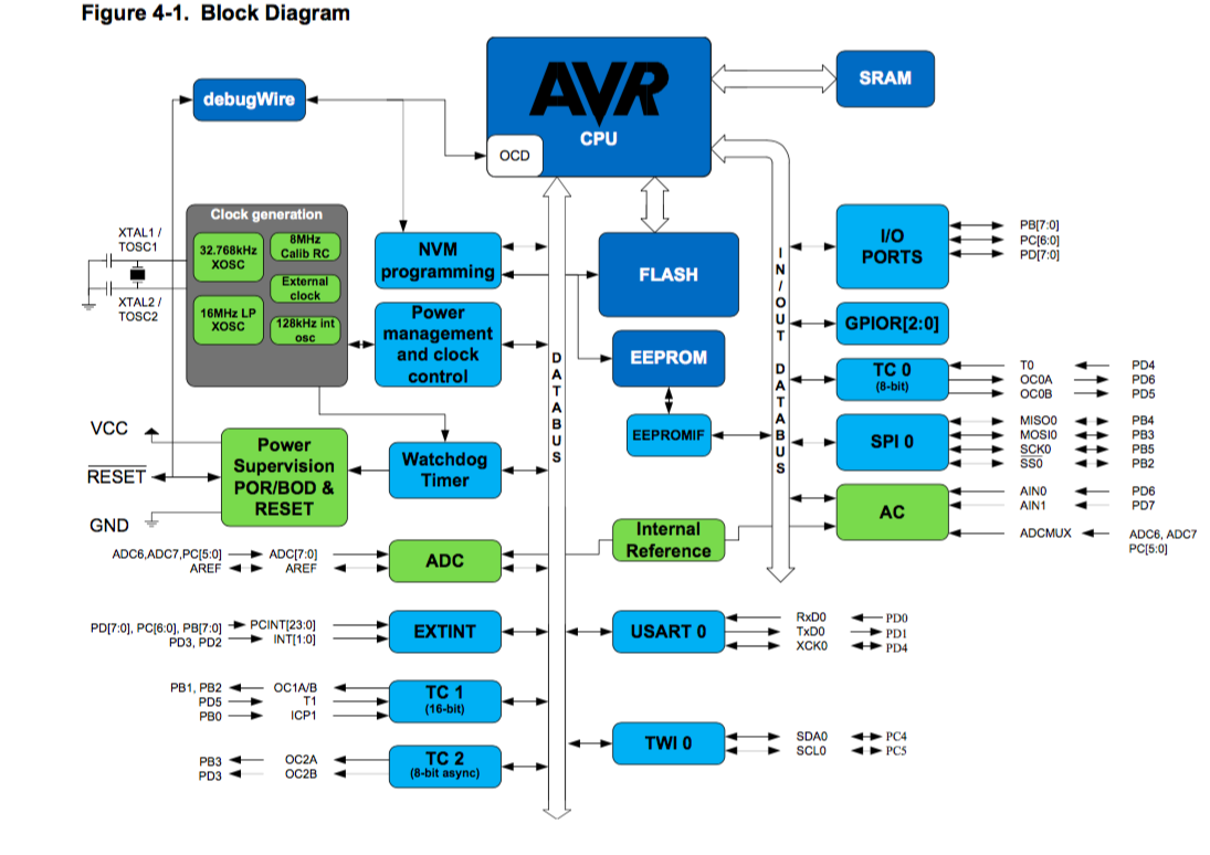
Below you can see the block diagram how the output and input pins are connected to the CPU /(Central Processing Unit).
Programming ATmega328p
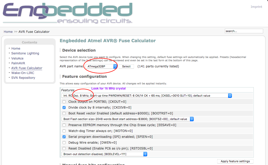
Now I want to program my ATmega328p board. For this I downloaded "Makefile.c" from Fab Academy site and addapted it to ATmega328p. In the following is to see which settings are to be changed in the Makefile according to MCU I used (ATmega328p).On this page you can calculate the fuses for your MCU.
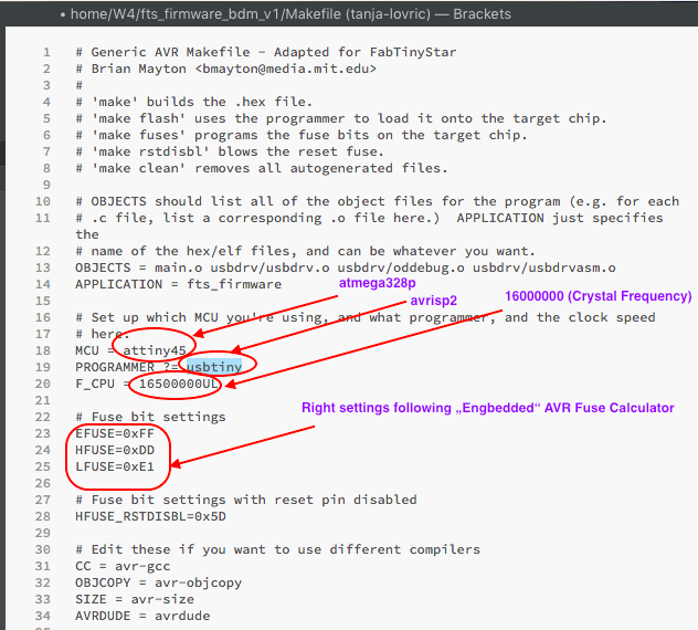
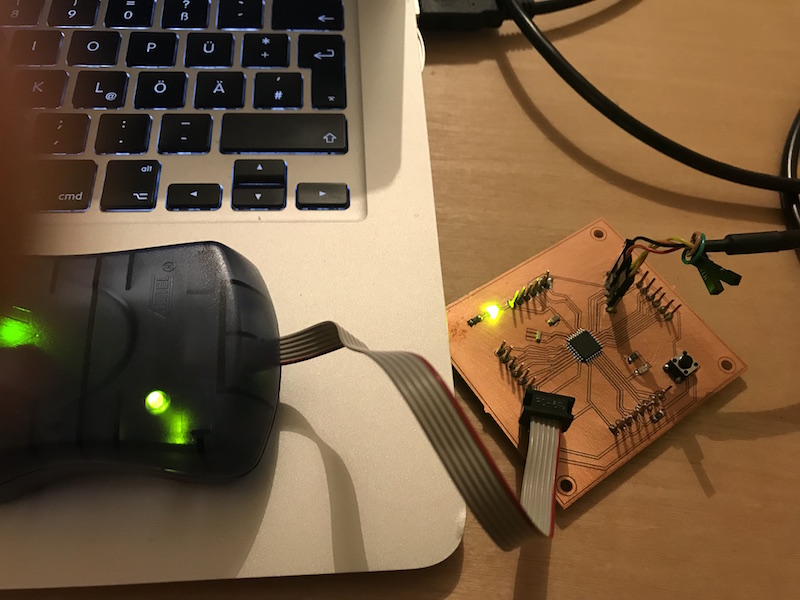
Using Arduino Uno as Programmer it is needed to set Fuses:
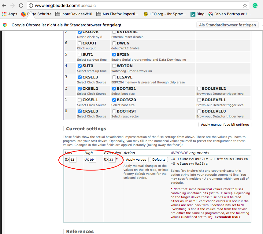
Fuses manualy settings
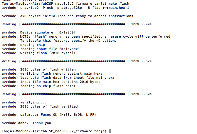
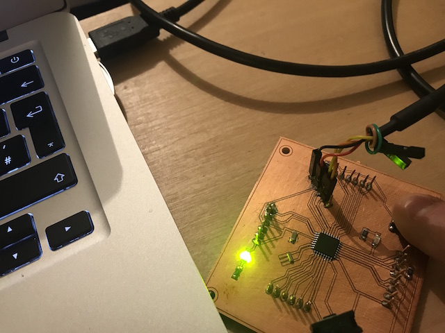
Below you can see the Makefile programming process:
Programm Tests with Atmega328p and Arduino IDE
I used the example codes from Arduino public domain to learn how the programm is built, how it works and to start some own programm experiments. I have to learn a lot about the proramming using c++.
Button Press
    int buttonPin = A0;              // here I define the the pin which will become the information about the button state
    int ledPin =  A1;                // here I define the pin which will give the information to the LED


    int buttState = 0;               // this variable should become the information about the button status


    void setup() {                   // void setup is the main program

      pinMode(ledPin, OUTPUT);       // here I tell the MCU that the LED pin will have to give some output
      pinMode(buttonPin, INPUT);     // here I tell Arduino IDE  that the button will give some input
    }

    void loop() {                     // void loop I need for contineous repating of the commands contained


      buttonState = digitalRead(buttonPin);   // read the the button(pin) state and save it into variable "buttState"


      if (buttonState == HIGH) {              // check if the button is pressed (level = high = 5V)

        digitalWrite(ledPin, HIGH);           // if button is pressed turn LED on (5V)
      } else {

        digitalWrite(ledPin, LOW);            // else if the button state is not pressed, turn LED off (0 V)
      }
    }
    void setup() {                   // the setup function runs once when you press reset or power the board


        pinMode(A1, OUTPUT);         // here I define the pin which will give the information to the LED

        }

    void loop() {                   // void loop I need for continueous repating of the commands contained

      digitalWrite(A1, HIGH);       // turn the LED on (5V)

      delay(1000);                  // wait for one second (1000 ms)

      digitalWrite(A1, LOW);        // now turn the LED off. to do this set the voltage LOW

      delay(5000);                  // wait for five seconds (this causes slow blinking)
    }
Fast blinking LED code
    void setup() {

        pinMode(A1, OUTPUT);
    }


    void loop() {

      digitalWrite(A1, HIGH);   // turn the LED on (HIGH is the voltage level)

      delay(1000);                       // wait for a second

      digitalWrite(A1, LOW);    // turn the LED off by making the voltage LOW

      delay(1000);                       // wait for a second
    }
Downloads
| Atmega328p_Button.ino | download |
| Blinking_slow.ino | download |
| Blinkneu.ino | download |