Week 7: Computer-Controlled Machining
First off all I would like to thank our guru from FabLab Kamp-Lintfort Daniele Ingrassia and colegue from Kamp-Lintfort
Ahmed Bilal for great support in this week and using the milling machine in their lab. Many thanks also to Jimena Galvez Paredes my student colegue in Bottrop for her support with Rhino and to Marcel Kellner my colegue from Bottrop for support in this week.
In this week we had to mill something big on a shopbot. The aim was to learn preparing data for a big CNC machine.
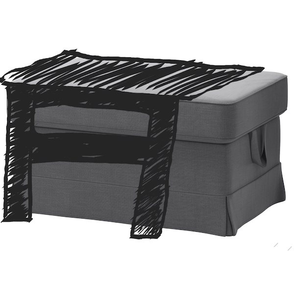
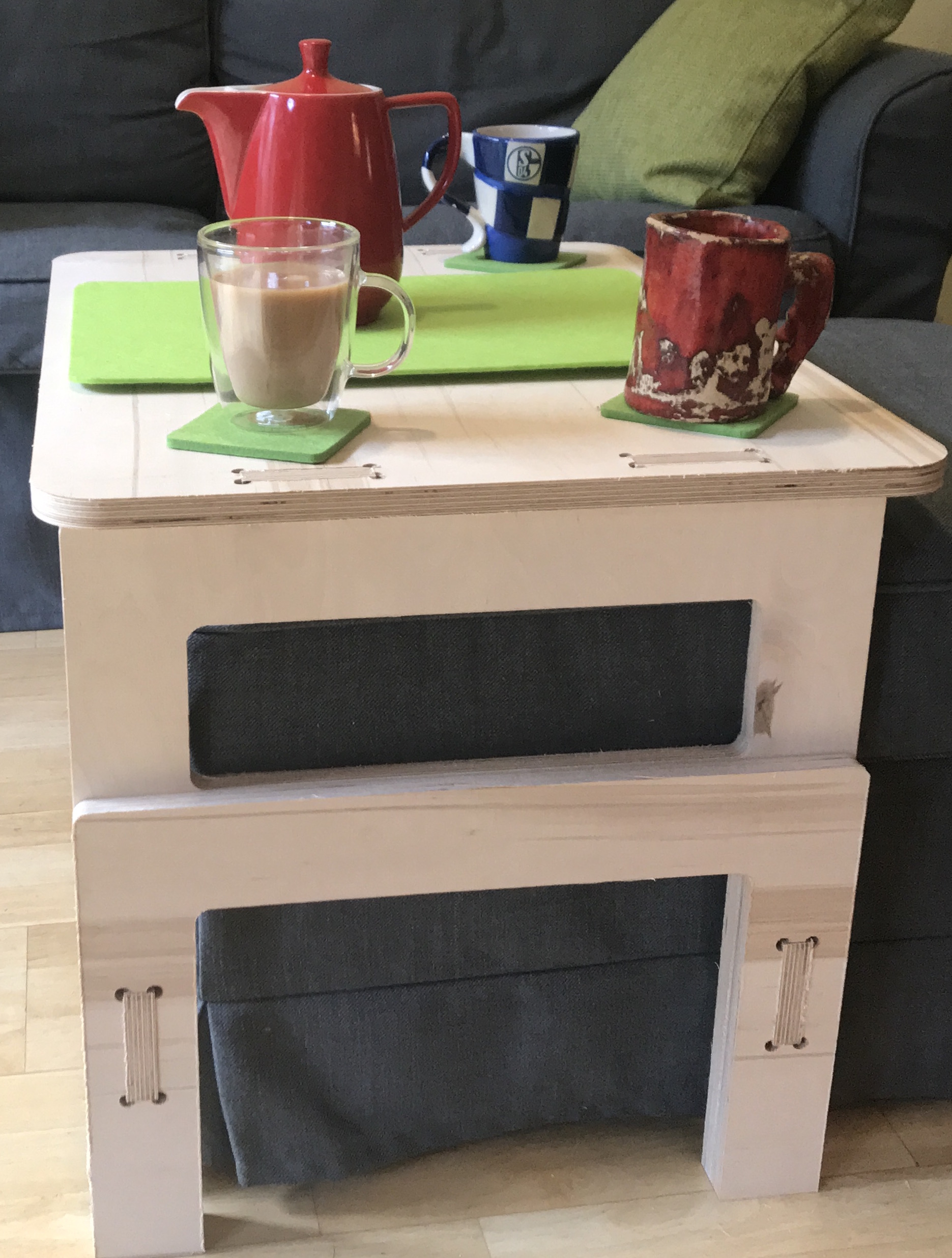
I have created a simple table. This table can be pushed over the IKEA footstool if you have a visitor and want to put glasses on it or put it aside, if you want to put your feet on the footstool.
3D Design of the table
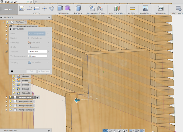
I designed a table using Fusion 360. First I skeched the shape of the table and draw the nodes.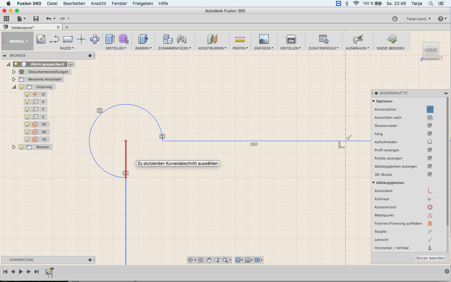
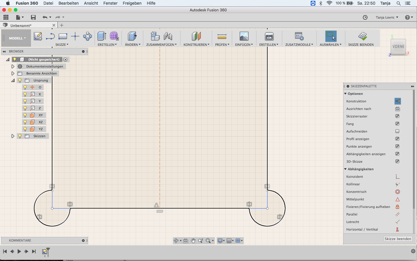
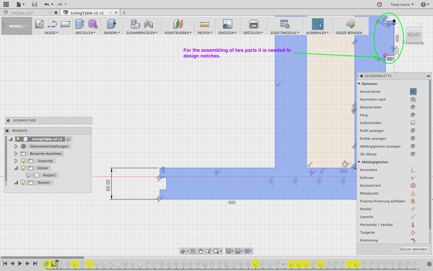
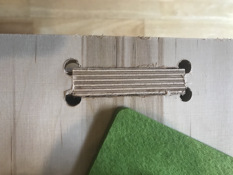
For that I had to take care about assambling problems defined by the milling tool. It is important to design a notch in the inner corner of each joint to be able to assemble the elements properly. Otherwise the milling tool would not be able to reach the corner and there would be a radius left over in each corner.
To be able to design the right dimension of the notch I had to know which milling tool we would use on the big milling machine. So I adjusted all those dimensions to the 6 mm tool before milling job in Kamp Lintfort.
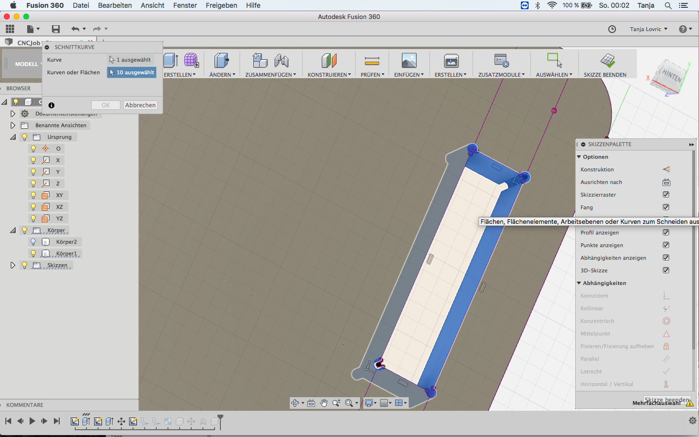
This is the adjusted node.
I had two options to change the nodes. First option was to take the front view of my table model and to draw a new skech of the notch on the surface. By doing this I could cut out through all legs of the table at once.
The second option was to change using parametric tool. There I have made a mistake because I had forgotten to use parametric design.
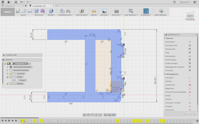
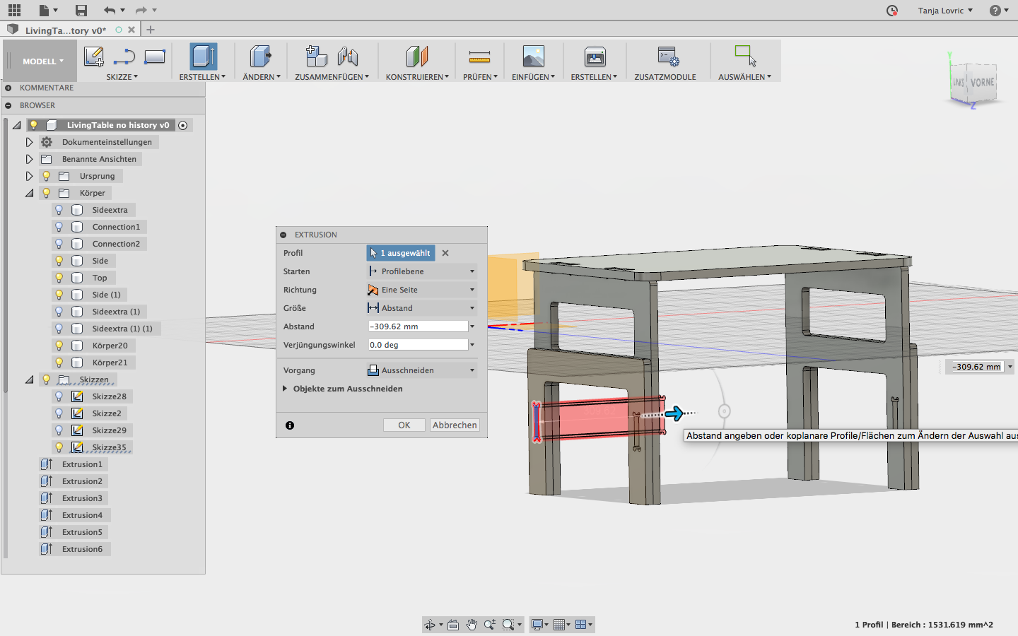
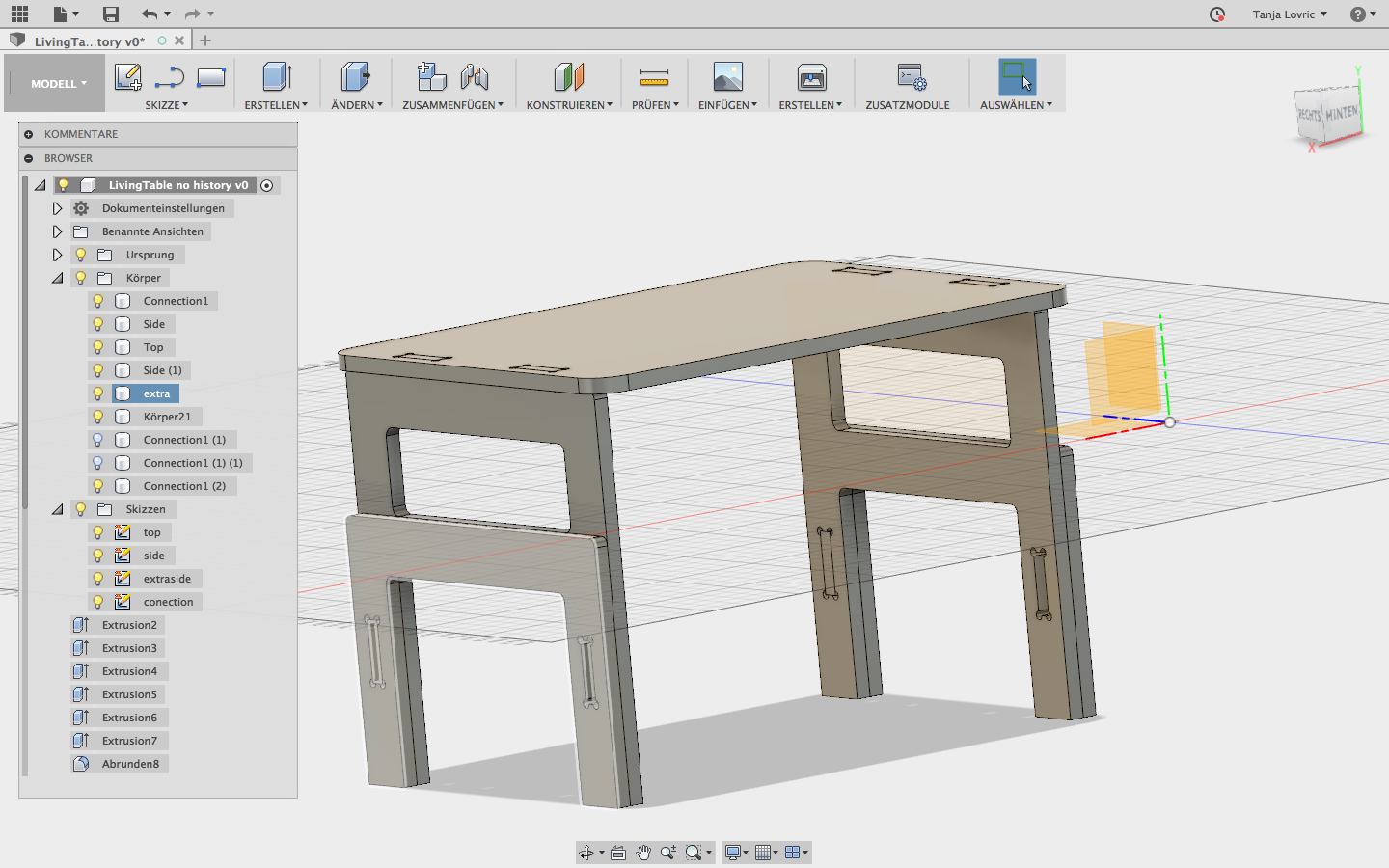
Above you can see the finished table design without texture optic.
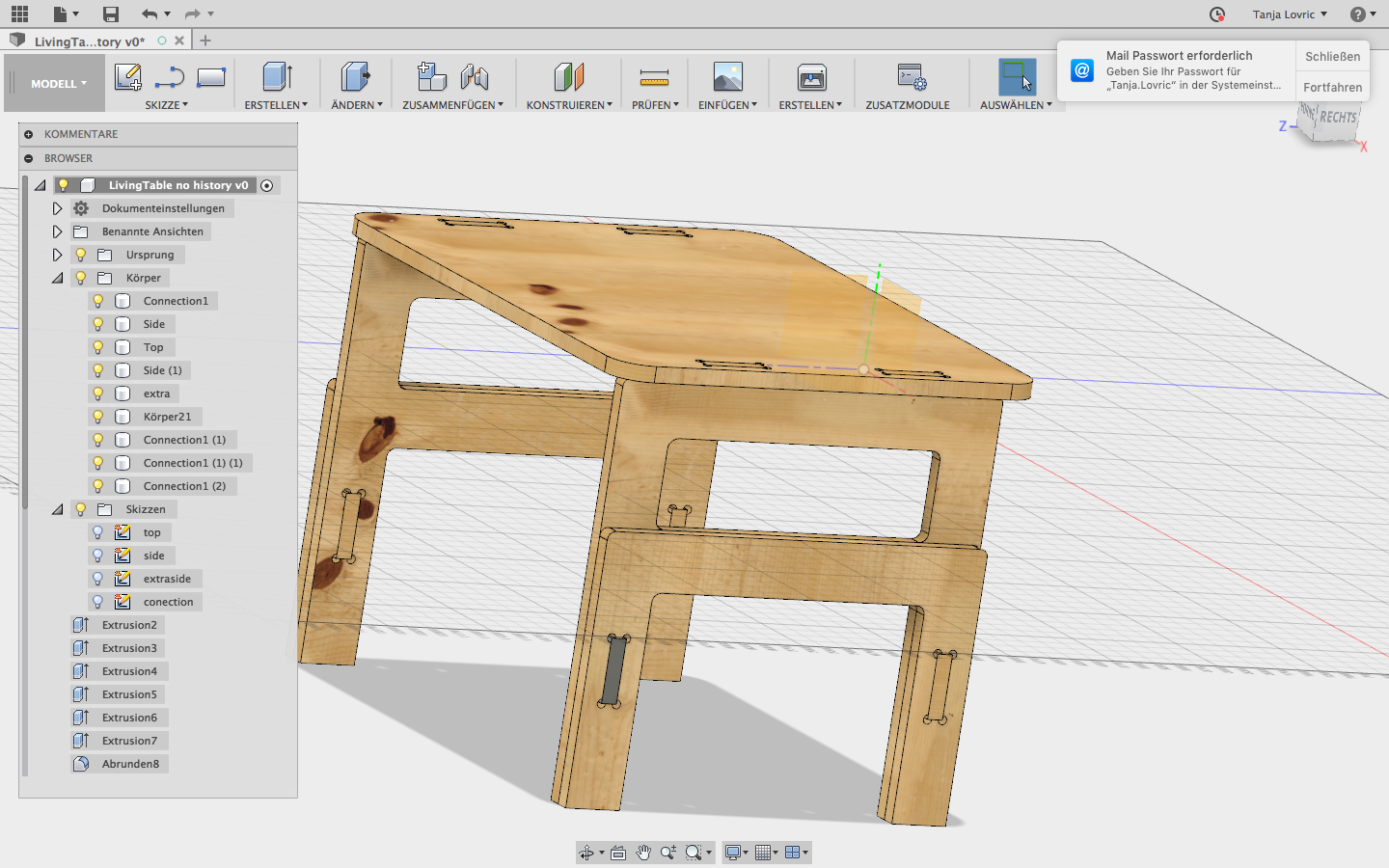
Wooden material optic can bee choosen‚ with the right klick in the Fusion 360 menue "Appearance/Texture". It will pop up separate window where in this library you can choose one of many wooden surfaces.
After finishing my design in Fusion I had to prepare the model for the milling process. I used Rhino program to clean up the double, interrupted and overlapping lines.
Rhino for 2D Design
After the design was finished, it should be exported to Rhino or other an suitable programm which is able to proof whether the design is CNC machinig ready. The part were placed due to use the whole wood surface optimally, so we do not have to use a second wood sheet.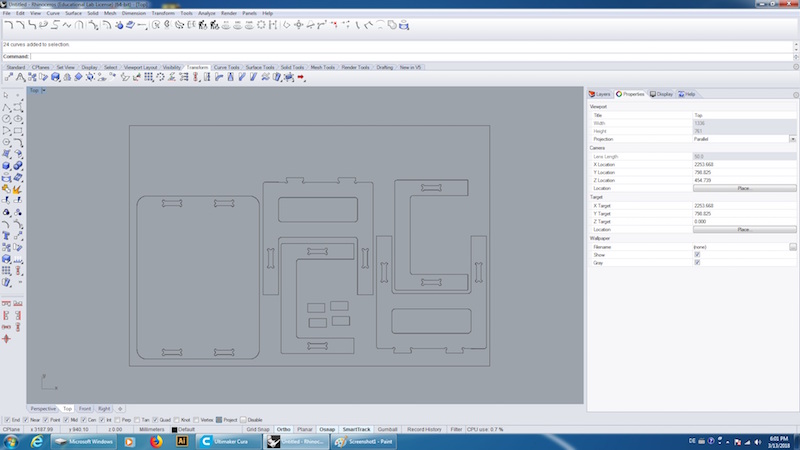
The outer and inner lines had to be separated into two different layers (red: inner lines and green: outer lines). Later the inner lines should be cutted first.
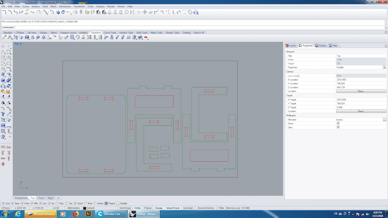
Now the design was ready to be milled.
Milling Machine
The working area of EasyWorker Pro is 2600 x 1400 x 300mm. easy worker Master Pro 2513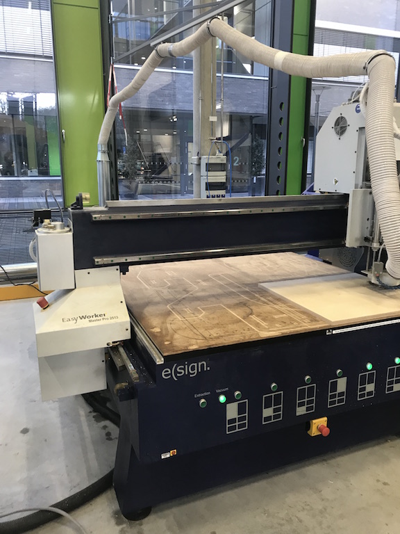
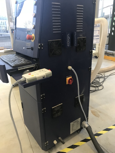
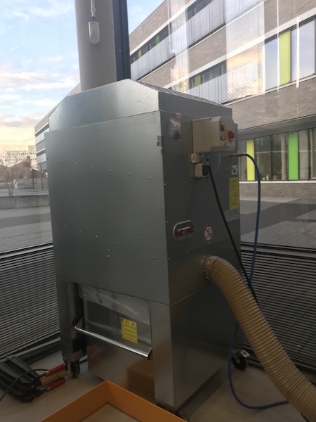
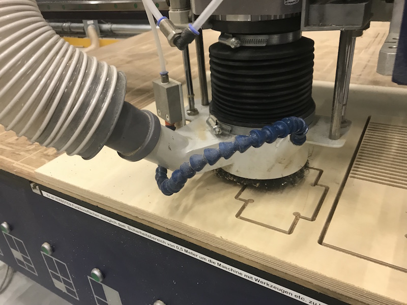
After reading of security instructions we started the dust extraction. The dust extraction is mounted at the milling motor and connected to a vacuum. The dust extraction is pneumatical height adjustable and absorbs material rests, turnings or dust.
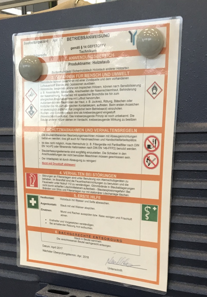
Safety instructions for working with big CNC machine:
- Only trained employees may operate the machine
- Danger of crushing by moving parts
- Danger of being caught by the spindle or workpieces
- Order and cleanliness in the workplace must be ensured
- Wear safety clothing (safety glasses, safety shoes, dust mask, ear protection, no gloves!)
- Keep a safe distance to the running machine
- Long hair should be tied or protected in a net
- No rings, watches and bracelets
- Clothes should be tight, especially sleeves
- Never measure, clean or repair faults while the machine is running

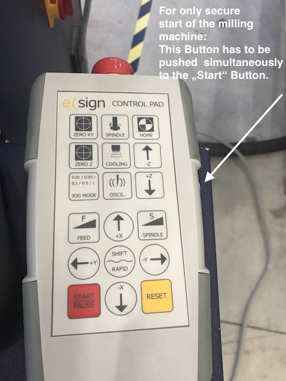
The control pad enables you to manually control movements at a single push of a button.
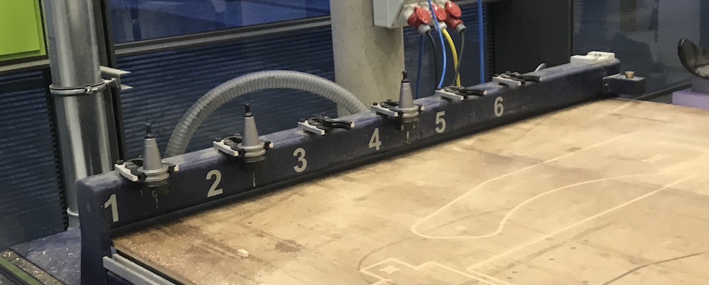
Up to 10 tools can be changed automatically during one working process saving precious production time. Flexible number of tools as per customer needs, automatic measuring and saving of tool-length, dust collector which is pneumatic height adjustable, tool saver and changing station for quick on-site milling bit changing at the linearbar.
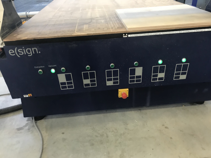
As the vacuum table of the milling machine was clean, we could place and align the wood peace and activate the affordable areas of the vacuum table.
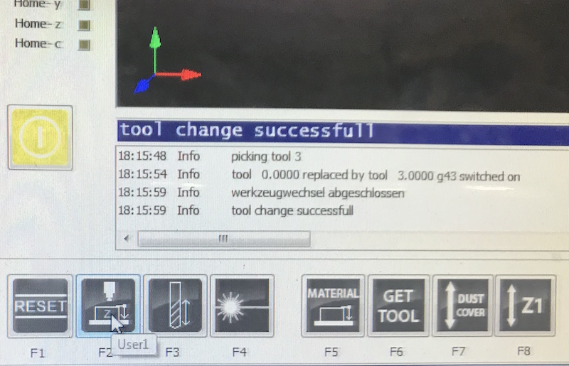
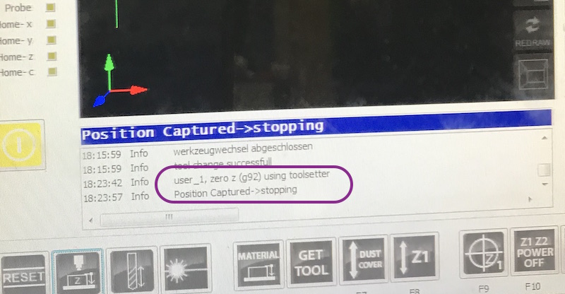
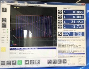
X/Y and Z-Positioning of the Milling Tool and Tool Change:
Using CNC tool length sensor the length of a tool is measured automatically.
For the Z axis positioning we used the height sensor. We have placed it on the wood sheet, then we have moved the milling head until it stud above the sensor. We pressed automatic calibration. The mill head has moved very slowly until the milling tool has pressed the height sensor.
Next images show the tool changing and z-positioning process.
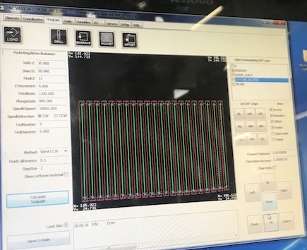
Milling Job
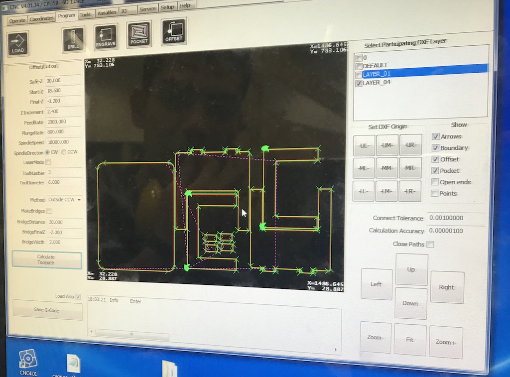
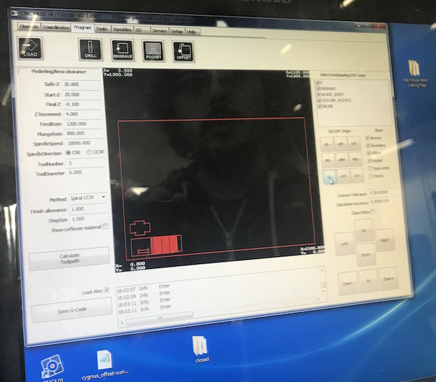
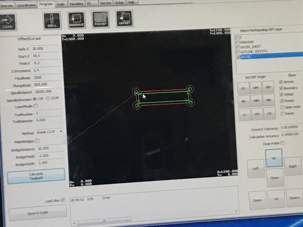
Now I loaded the Rhino file to the controller of the CNC machine. Inline and Outline layers has to be cutted separately. Due to this I switched off the Outline layer first.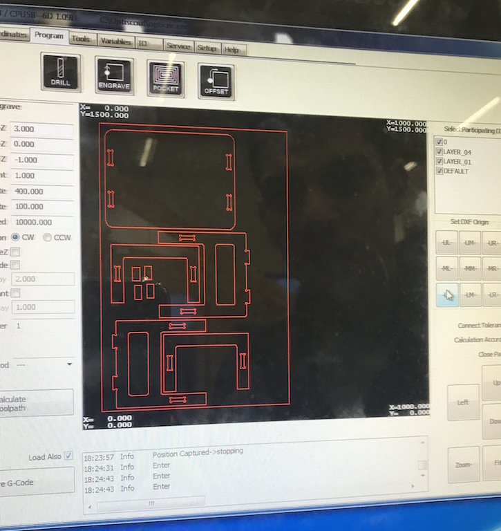
Following settings were needed: OFFSET / CUT OUT
Safe-Z: 30
Start-Z: 18.5
Final-Z: -0.2 mm (to cut trough the material)
Z Increment: 2.4 (it depends on the each wood sheet thickness)
FeedRate: 2000 mm/min
PlungeRate: 800 mm/min
SpindleSpeed 18000.000 rpm
SpindleDirection CW (clockwise)
ToolNumber: 3
Laser Mode: OFF
Time total (Inlines): 20:30 min
Time total (Outlines): 57:12 min
ToolDiameter: 6.000 (mm)
Method: Inside CCW (for Inlines) and later Outside CCW (for Outlines)
To calculate the toolpath I pressed the button and saved the G-Code on the computer. As both layers were loaded I had to deselect the outlines. Now only the Inlines were visible.
Later in the second step I loaded the outlines ...
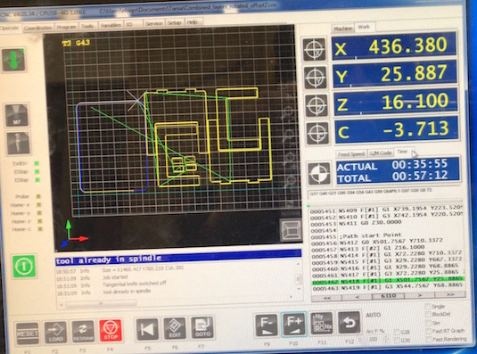
... callculated the toolpath, caved the G-Code and started the milling job again.
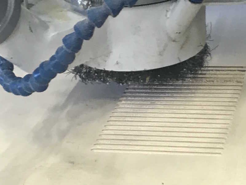
Some movies which show the milling process:
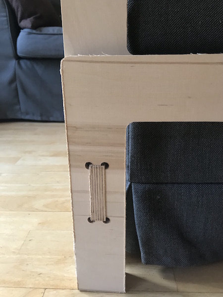
Assembling the Parts
It was quite easy to assemble the parts. I designed two supporting short parts for the sides because I would like to add some small wheels under the table-legs.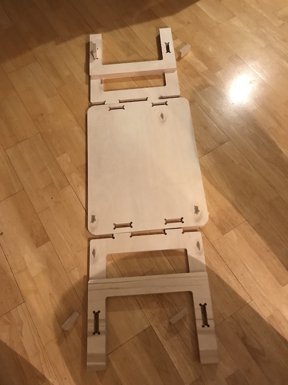
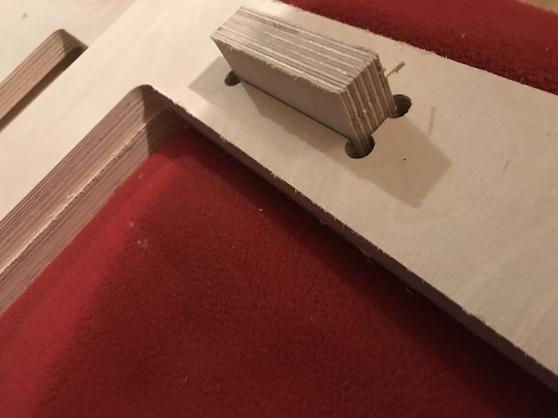
It took some solid hammer blows on the connectors and the table parts were connected.
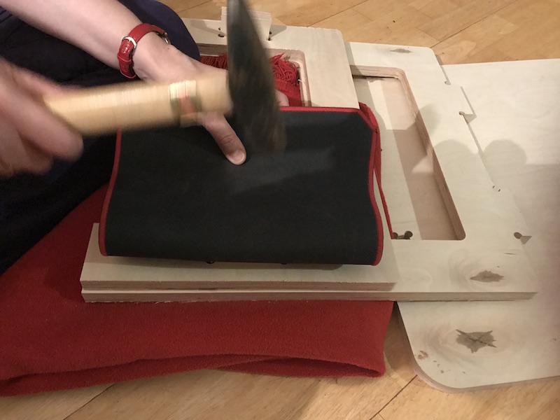
The table was wery stable even if it had no squer connections on both sides. Now I have to grind the table surface and treat it with wood stain to protect it against the stains.
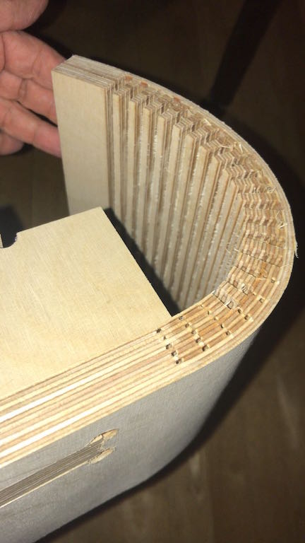
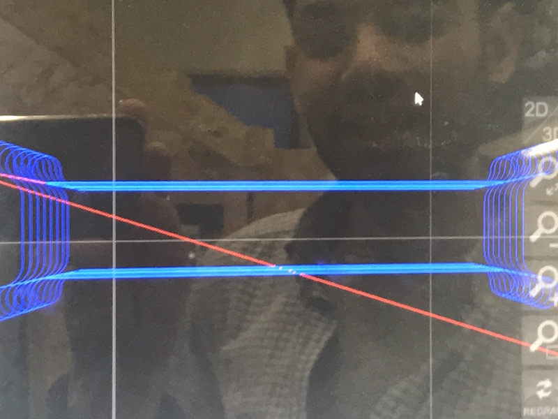
Groupassignment: Kurve Bending Test
I made some tests with kurve banding because I like this technik of wood preparation very much. I was inspired through the project of my colleuge Aleksandra Konopek from her "Makes Something Big" week in 2017.
I loaded up following Rhino file to the controller of the Easy Maker Pro:

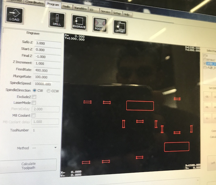
Following settings were needed for Kurve Bend Milling:
ENGRAVE
Safe-Z: 30
Start-Z: 20
Final-Z: 17 mm (no cut trough the material!!)
Z Increment: 4
FeedRate: 1200 mm/min
PlungeRate: 800 mm/min
SpindleSpeed 18000.000 rpm
SpindleDirection CW (clockwise)
ToolNumber: 3
Laser Mode: OFF
Time total: 10:00 min
ToolDiameter: 6.000 (mm)
Method: Inside Spiral CCW (for Engraving)
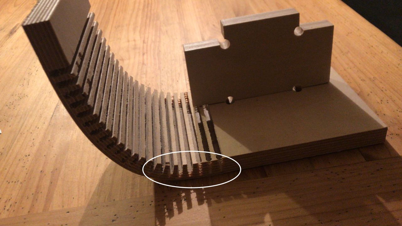
Following images show the loaded testfile with kurve bending, one T-Bone connector and the hole after calculating the toolpath.
Following images show the increments of the tootlpath for the T-Bone, caleculated toolpath for the kurve bending and the progress of the milling process.
The following short movies show fast forward milling process of kurve bending.
For the kurve bending I have choosen the "Engraving" cutting option because the cut should not go through.
After milling of the test part was finished, I assembled the t-bone connector with the hole with a several powerful hammer strokes. The connection was very stable.
As the test cut was finished I burnished it at several places and tried to bend it. I worked werdy good. Later I make some tests using hot water and sprikled the test part with it, bend it and pressed it with some books. I left it get dry during one night.

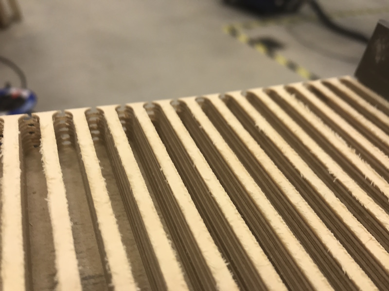
The next day it was dry and stayed in form as wished (90 deg).