Output Devices
The assigment page
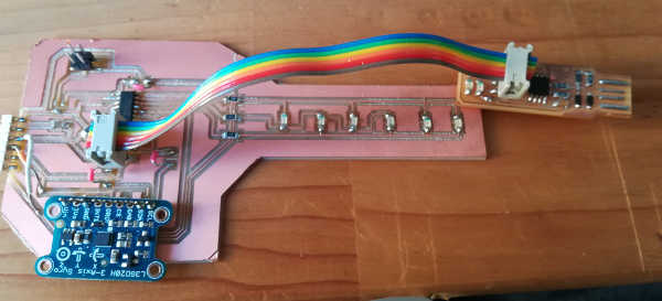
The goal of this week was to design a board with an output device and program it.
⇝ Designing the board ⇝ Milling the board ⇝ Program the board
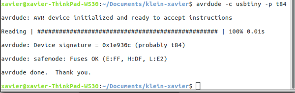
First thing, I checked if the board's working. Classic avrdude -c usbtiny -p t84.
It's working.
I couldn't find the resonator in my parts, perhaps I forgot to take one in Amsterdam. So when I burned the bootloader (Check here to know how I did it), I set the clock to Internal 8 Mhz.
I tried the code from the tutorial I followed.
Now, if you look at images of the board above, something is missing. The regulator. If you're already noticed it you win this "Very Good Eyes" cup:

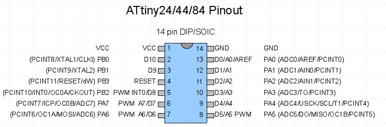
I try first with the code above, I change the pins, looking to this type of datasheet:
I've upload the code and nothing happened. The regulator started to fried!
It fried because I put it there to regulate a 9V from a battery to 5V. But there was no battery when I tested the code (using the programmer as power supply) and the regulator didn't enjoy it.
So for the next "experiments" I remove it and used only the programmer as power supply.
I manage to make CharliePlexing working with the good pins, I've made some mods to the code in order to have a back and forth movement (you check this code here.):
Here's the beast:
The code:
T
/*
* Charlieplexing code for this board:
* http://archive.fabacademy.org/2018/labs/fablabamsterdam/students/klein-xavier/pages/week11/file/ledboard.zip
* WTFPL Xavier Klein
*/
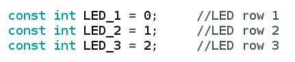
Here I have 3 variables related to the 3 pins I dedicated to for each row.
//Setting the pin for each row.
const int LED_1 = 0; //LED row 1
const int LED_2 = 1; //LED row 2
const int LED_3 = 2; //LED row 3
//Nothing in void setup()
void setup()
{
}
void loop()
{
Here, I program the sequence of LED. I turn on a LED for 100ms, turn off, and turn on the other one etc.
For each LED you have to set a state for the 3 pins (digitalWrite HIGH or LOW and pinMODE Output or Input).
Honestly I proceeded with try and error to set each LED.
//turn on LED 1
pinMode(LED_1, OUTPUT); //row 1
digitalWrite(LED_1, LOW);
pinMode(LED_2, OUTPUT); //row 2
digitalWrite(LED_2, HIGH);
pinMode(LED_3, INPUT); //row 3
digitalWrite(LED_3, LOW);
delay(100);
//turn on LED L2
pinMode(LED_1, INPUT); //row 1
digitalWrite(LED_1, LOW);
pinMode(LED_2, OUTPUT); //row 2
digitalWrite(LED_2, LOW);
pinMode(LED_3, OUTPUT); //row 3
digitalWrite(LED_3, HIGH);
delay(100);
//turn on LED L3
pinMode(LED_1, OUTPUT); //row 1
digitalWrite(LED_1, HIGH);
pinMode(LED_2, OUTPUT); //row 2
digitalWrite(LED_2, LOW);
pinMode(LED_3, INPUT); //row 3
digitalWrite(LED_3, LOW);
delay(100);
//turn on LED L4
pinMode(LED_1, INPUT); //row 1
digitalWrite(LED_1, LOW);
pinMode(LED_2, OUTPUT); //row 2
digitalWrite(LED_2, HIGH);
pinMode(LED_3, OUTPUT); //row 3
digitalWrite(LED_3, LOW);
delay(100);
//turn on LED L5
pinMode(LED_1, OUTPUT); //row 1
digitalWrite(LED_1, LOW);
pinMode(LED_2, INPUT); //row 2
digitalWrite(LED_2, LOW);
pinMode(LED_3, OUTPUT); //row3
digitalWrite(LED_3, HIGH);
delay(100);
//turn on LED L6
pinMode(LED_1, OUTPUT);
digitalWrite(LED_1, HIGH);
pinMode(LED_2, INPUT);
digitalWrite(LED_2, LOW);
pinMode(LED_3, OUTPUT);
digitalWrite(LED_3, LOW);
delay(100);
//turn on LED L5
pinMode(LED_1, OUTPUT); //row 1
digitalWrite(LED_1, LOW);
pinMode(LED_2, INPUT); //row 2
digitalWrite(LED_2, LOW);
pinMode(LED_3, OUTPUT); //row3
digitalWrite(LED_3, HIGH);
delay(100);
//turn on LED L4
pinMode(LED_1, INPUT); //row 1
digitalWrite(LED_1, LOW);
pinMode(LED_2, OUTPUT); //row 2
digitalWrite(LED_2, HIGH);
pinMode(LED_3, OUTPUT); //row 3
digitalWrite(LED_3, LOW);
delay(100);
//turn on LED L3
pinMode(LED_1, OUTPUT); //row 1
digitalWrite(LED_1, HIGH);
pinMode(LED_2, OUTPUT); //row 2
digitalWrite(LED_2, LOW);
pinMode(LED_3, INPUT); //row 3
digitalWrite(LED_3, LOW);
delay(100);
//turn on LED L2
pinMode(LED_1, INPUT); //row 1
digitalWrite(LED_1, LOW);
pinMode(LED_2, OUTPUT); //row 2
digitalWrite(LED_2, LOW);
pinMode(LED_3, OUTPUT); //row 3
digitalWrite(LED_3, HIGH);
delay(100);
}
Mixing Input and Output
So I have my gauge. Now I have to use it with the Input, the gyroscope:
So I simply mix the code above and the code from last week.
In this code you set the gyroscope and you have serial prints of each axis degrees per seconds (DPS) like I explained last week.
So to trigger this code I'm simply reading the Z axis DPS and use in a condition to trigger one of the LED according to the DPS value of z axis.