Output Devices
The assigment page
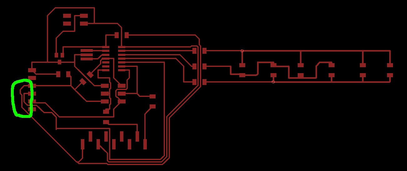
The goal of this week was to design a board with an output device and program it.
⇝ Designing the board ⇝ Milling the board ⇝ Program the board
So I use exactly the same process than last week to mill this board. Check this page.
Unfortinatly I forgot to took photo of the milling.
But I had a problem. The board was bigger that I was in mind and I had only one copper plate. I put my origin very close to the edge to be sure. A bit too close. This part was milled in the air.
So I had to make some surgery:
Also, as you can see the milling wasn't very clean. The surface wasn't completely flat and the board quite big. I didn't have problems with small boards because the Z zero is quite the same everywhere.
But here, one part of the board was good but one other was too close to the endmill. So it didn't mill very well and I had to force a bit to extract the board from the copper sheet.
I was using a CNC who's not dedicated to board milling. So the sacrificial layer isn't perfectly flat. Someone told me to surface an aluminium sheet and screw it to the bed. I'll make it if I have time.
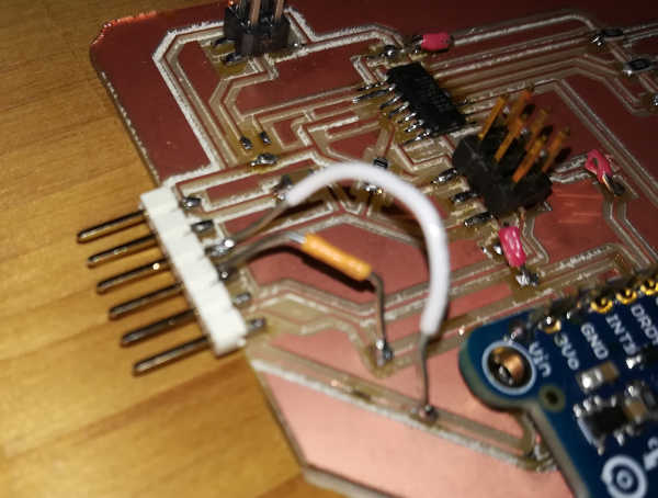
And here the final board. I solder the gyro directly to the 9 pins header and I didn't have 0 Ohm resistors so I use jumpers wires.
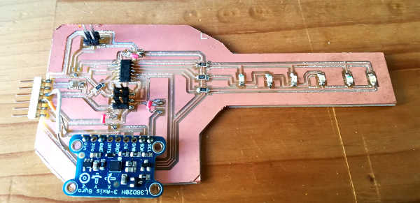
Now it's ready to be programmed!