Input Devices
The assigment page
The goal of this week was to design a board with an input device and program it.
⇝ Designing the board ⇝ Milling the board ⇝ Program the board
For this week, I didn't use the Modela at Waag, I wanted to try with the small CNC at imal.
There's a wiki, called WikImal, perhaps there's some instructions for PCB:
...
...
...
...
...
...

The wikimal is accessible to users so now I know my next assigment on it.
I try first to export in png, vectorise it and select only contours and then save it in DXF.
I open it in Fusion360, extrude it and try to play with CAM module. There's nothing satisfying.
I thought a bit and tell to myself: "Xavier, s'ils l'ont déjà fait, ils ont dû utiliser un logiciel là-bas."
I know that the CNC can be control with a software called Galaad.
It's a very interesting bad looking software and it has a PCB module! Hooray! It's called Percival. To open a board in Percival, you have to open it in Eagle first:
-Go to File -> CAM Processor
-A window appear, select Top Copper below "Gerber" and click on "Export File" to export it.
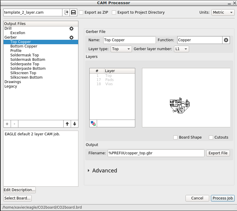
You can close it, Eagle as well. Put your new .GBR file on a USB stick and connect it into the computer.
Open Percival and open your file To generate toolpath, I use this tutorial. It's very simple.
1. Select the origin by right-clicking and select set the origin
2. Click on Calcul Contour. A window appear asking the number of contour you want.

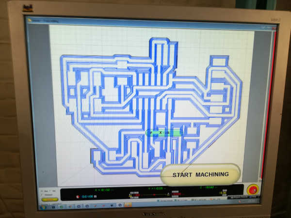
3. The sofware will start to process:
4. It will show you the final result:
And finaly I click "milling". It's open Galaad, where you can choose your tool and settings:
For engraving:
-A 0.4mm conical end mill, at 12000 rpm.
For cutting:
-A 0.9mm flat end mill at 15000 rpm.
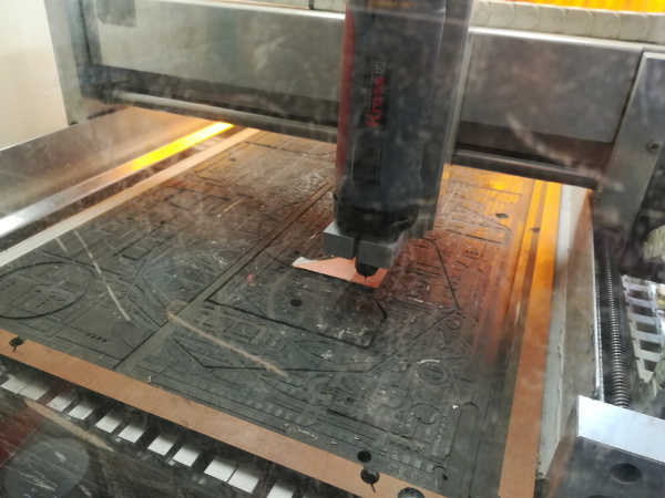
In Galaad, I design the board's edge and launch the milling.
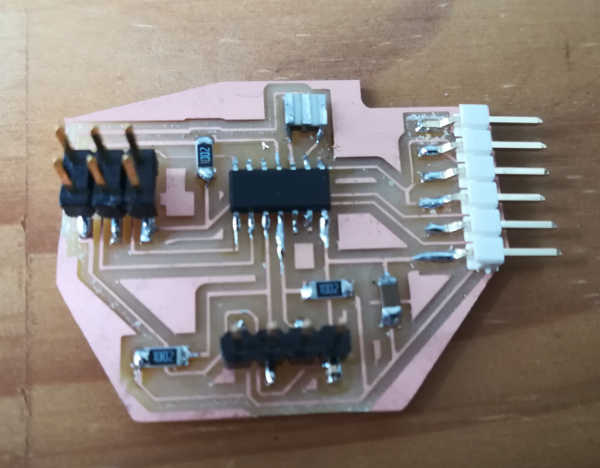
The first board has very thin pads, I think it's because I clicked on an option in Percival to reduce the pad.
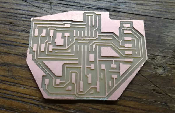
I solder the component and try to program it.