Week 1 assignment
Principles and practices, project management (Jan 28)
Week 2 assignment
Computer-aided design (Feb 4)
Week 3 assignment
Computer-controlled cutting (Feb 11)
Week 4 assignment
Electronics production (Feb 18)
Week 5 assignment
3D scanning and printing (Feb 25)
Week 6 assignment
Electronics design (Mar 4)
Week 7 assignment
Embedded programming (Mar 11)
Week 8 assignment
Computer-controlled machining (Mar 18)
Week 9 assignment
Molding and casting (Mar 25)
Week 10 assignment
Input devices (Apr 8)
Week 11 assignment
Output devices (Apr 15)
Week 12 assignment
Composites (Apr 22)
Week 13 assignment
Networking and communications (Apr 29)
Week 14 assignment
Mechanical design, machine design (May 6)
Week 15 assignment
Interface and application programming (May 13)
Week 16 assignment
Applications and implications (May 20)
Week 17 assignment
Invention, intellectual property, and income (May 27)
Week 18 assignment
Project development (Jun 3)
Week 19 assignment
Project presentation (Jun 10)
Embedded programming (Mar 11)
This week we had to read a data sheet. Data sheets are not so easy to read also because they are written in technical language. You need patience..:) They are full of information and it is easy getting confused with them. I think that you have to focus on what you really need ignoring the rest. Otherwise it could be easy getting frustrated because of you don’t understand the most of what it is written :) Moreover, this week we had to program the Hello board we did last week. Thanks to our local instructor advices I did a little example even using the interrupts. In the end, I did a little experience with PSoC board because maybe it could be useful for my final project.
Summary:
- Setup
- Makefile
- Button and led code
- First steps with interrupts
- First steps with PSoC
- Conclusions
- Files
Setup
Under Linux (I use Linux Mint) I had to install these packages.
sudo apt-get install gcc-avr
sudo apt-get install avrdude
sudo apt-get install avr-libc
Makefile
From Wikipedia:
Makefile(s) are text files written in a certain prescribed syntax. Together with Make Utility, it helps build a software from its source files, a way to organize code, and its compilation and linking.
Our local instructor helped us to build a simple Makefile:
PROJECT=blink
SOURCES=$(PROJECT).c
MMCU=attiny44
F_CPU = 20000000
CFLAGS=-mmcu=$(MMCU) -Wall -Os -DF_CPU=$(F_CPU)
$(PROJECT).hex: $(PROJECT).out
avr-objcopy -O ihex $(PROJECT).out $(PROJECT).c.hex;\
avr-size --mcu=$(MMCU) --format=avr $(PROJECT).out
$(PROJECT).out: $(SOURCES)
avr-gcc $(CFLAGS) -I./ -o $(PROJECT).out $(SOURCES)
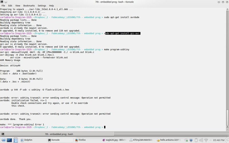
program-usbtiny: $(PROJECT).hex
avrdude -p t44 -P usb -c usbtiny -U flash:w:$(PROJECT).c.hex
program-usbtiny-fuses: $(PROJECT).hex
avrdude -p t44 -P usb -c usbtiny -U lfuse:w:0x5E:m
The first lines are the variables. CFLAGS are some options useful when the compiler (gcc-avr) will generate the .out file. The compiler needs the .out file to create the .hex file which is the file that we will upload into our board. When I write the compiler needs I am highlighting a chain of dependencies:
- .out file needs .c file (the source code)
- .hex file needs .out file.
Using Makefile helps us with the management of these dependencies. Be careful that those spaces under the lines with $(PROJECT) are not useless. If you don’t use them you will get an error of this kind:
missing separator. stop.
The indented lines are the real commands you can also type in command line accurately replacing the variables.
program-usbtiny is what you need to upload the code into the board. Be careful that maybe you need root privileges to upload the code. I needed to use sudo: sudo make program-usbtiny.
program-usbtiny-fuses is useful to write the fuses on the attiny.
Button and led code
I started with this code reading the datasheet to understand how to blink the LED. Then I studied this code to understand how to use the button. Obviously you need to check the pins where your button and LED are connected modifying the source code. At the end of this page you will find the simple code I did.
Let’s start with the LED. It is crucial to understand that in order to program a microcontroller you need to set/unset some registers. You have to imagine them like many little switches. You can enable/disable them writing 1 or 0 into the right memory location. You also need to know some basics about binary logic and bitwise operators in C language. It could be helpful this page where you can find the truth tables to understand how AND, OR and other boolean operators work. All the values of the microcontroller “switches” give a particular configuration according to what you want to do with it.
Before I describe my code example it has to be clear how to use #define. You can find details here.
Using my example, I need to tell to the microcontroller that the pin PA7 (you can find it on the Eagle schematic at the end of this page Electronic design) is where I connected my LED then I want enable that pin as output. Relating to the Attiny44, you also have to tell which is the PORT your pin belongs to: PORTA or PORTB.
The default value written for all pins is 0, that is all pins are inputs. Basicly in order to enable a pin as output I have to write 1 into it. You can do it with OR logic operator:
DDRA |= (1 << PA7)
With 1 << PA7 you take a register (in our case register length is 8 bit) that you can imagine with all zeroes:
00000000
then you put the 1 on the first digit on the right:
00000001
and with << you say to shift that 1 for PA7 positions. How much is PA7 is written in avr/io.h.
In the end, using the OR logic operator you will enable exactly the bit you need without modifying the rest of DDRA register.
On the contrary, using AND with NOT operator you can do the opposite operation, that is you can write (disable) exactly the bit you need. We did it with:
PORTA &= ~(1 << PA7)
The line above is used to be sure that we start from a known condition, that is 0 in that pin.
DDRA is the Data Direction Register, you can find it at page 66 in the data sheet
PA7 is the pin where my LED is connected. Basicly PA7 is a number and you can find it in avr/io.h.
From now, I go on describing the code using parametric #define macro you can see in the first lines of my source code.
In order to use the button as input we do something similar we did with the LED:
input(input_direction, input_pin); // (DDRB &= ~(1 << PB2)) OPTIONAL!
This could be optional because all the pins are in input mode even if you don’t do anything.
The loop is the section of the code that is repeated continuously. You can see while(1) in the code.
Inside the loop you can see the line
while (0 != pin_test(input_pins,input_pin));
Here you do the logic AND between input_pins (PORTB) and the input_pin (1 « PB2) where the button is connected. If you don’t push the button the result of pin_test macro is a value different from 0 then you will have a continuous loop in that line. When you push the button you give to the input pin a voltage near zero which is interpreted by the microcontroller logic as 0. Now, the result of pin_test macro is a value equal to 0 then the next code line will be executed.
We enable the LED pin with:
set(led_port, led_pin);
we wait a little bit (the delay value is milliseconds):
led_delay();
then until you press the button you will have the LED on:
while (0 == pin_test(input_pins,input_pin));
after you release the button the LED will be turned off:
clear(led_port, led_pin);
and the loop repeated continuously.
First steps with interrupts
After I understood how to turn on the LED pushing the button I’d like start/stop the blinking pushing the button. It could look a simple job but it hides some tricky problems. I was thinking about it but if you don’t know how to use the interrupts it you have to do in a similar way written in this Advance button library.
In order to understand the example code that our local instructor show us (on the book Make AVR Programming) you have to read page 50 of the manual.
In the second example I did, what is important is the use of interrupts. They are some little pieces of code that are executed every time the microcontroller receives a signal in some dedicated pins. The important thing is that the microcontroller suspends everything it is executing to execute that little piece of code. For example, luckily, I had the button in a pin where I can use interrupt. In order to enable it I had to use:
GIMSK |= (1 << INT0); // enable INT0. (enable external pin interrupt (pag.50 datasheet))
In the following line I decided that Any logical change on INT0 generates an interrupt request.
MCUCR |= (1 << ISC00); // trigger when button changes (pag. 50 datasheet)
If you want to use the interrupt you have also to enable the I-bit in the Status Register and I did it with this line:
sei(); // set global interrupt when enable it. (enable SREG. we use I bit)
What I tried to experiment is to start/stop the blinking of the LED inverting the direction of LED port every time I pushed the button. You can see it in this line:
led_direction ^= led_pin;
in ISR(INT0_vect) function.
The result is in the video below
First steps with PSoC
This is the PSoC 4 CY8CKIT-049 4xxx Prototyping Kits

I followed this guide doing first examples. Even if I did these examples with success I feel that I have to go in depth to understand what I can really do with this board and which are its pros and cons.
Here below where you can modify the delay of blinking LED.
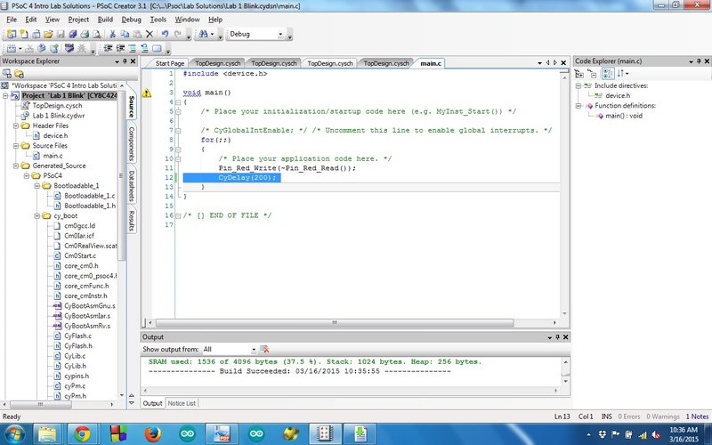
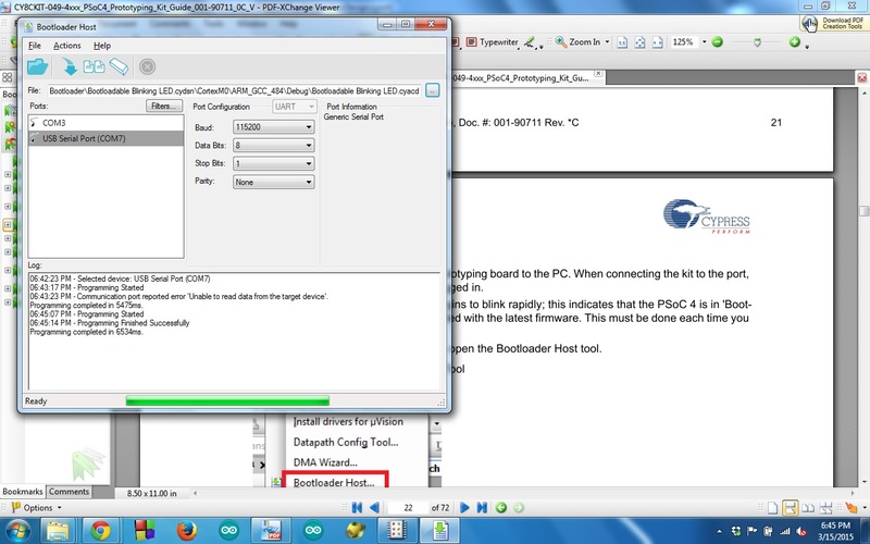
In order to get the board ready to upload your code you have to push the button (there is only one button) while you connect it to the USB port. You will see the blue LED blinking fast.
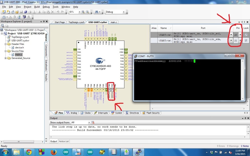
Here below the example about using the UART. The characters are duplicated because of local echo option in PutTy. In this way you can see what you type and what you receive from the board.
I am curious about going in depth with this board. I hope I will find more simple examples :)
Conclusions
I like programming and I am curious about programming a little computer like a microcontroller. I really understood that I have to study more about programming and expecially embedded programming. I’d like to explore more the world of embedded programming but I am a bit lost in all the documents you can find. I need a guide but not a boring one, something with many funny examples in order to learn while enjoying :)
Project files
Here are the files. You can find:
- first code example with LED and button
- second code example using interrupts