Week 1 assignment
Principles and practices, project management (Jan 28)
Week 2 assignment
Computer-aided design (Feb 4)
Week 3 assignment
Computer-controlled cutting (Feb 11)
Week 4 assignment
Electronics production (Feb 18)
Week 5 assignment
3D scanning and printing (Feb 25)
Week 6 assignment
Electronics design (Mar 4)
Week 7 assignment
Embedded programming (Mar 11)
Week 8 assignment
Computer-controlled machining (Mar 18)
Week 9 assignment
Molding and casting (Mar 25)
Week 10 assignment
Input devices (Apr 8)
Week 11 assignment
Output devices (Apr 15)
Week 12 assignment
Composites (Apr 22)
Week 13 assignment
Networking and communications (Apr 29)
Week 14 assignment
Mechanical design, machine design (May 6)
Week 15 assignment
Interface and application programming (May 13)
Week 16 assignment
Applications and implications (May 20)
Week 17 assignment
Invention, intellectual property, and income (May 27)
Week 18 assignment
Project development (Jun 3)
Week 19 assignment
Project presentation (Jun 10)
Computer-aided design (Feb 4)
Summary:
This week I tried to design the waterproof container which will host the electronic board of my device. I though about something like this below but with some modifications. You can find all the files at the bottom of this page.
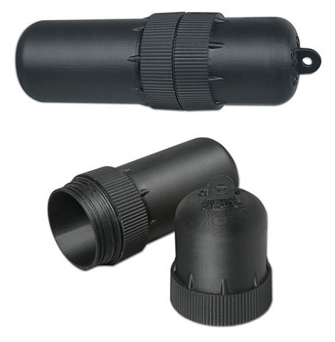
In the last days I read more about hydrophones and I think I will use it for my final project. I will use a piezo to do the hydrophone. Ideally the piezo would be in direct contact with water, but obviously it cannot. It will be connected to the board with all the electronic. Therefore the piezo would adhere as much as possibile to the waterproof container. In this way it will reveal at his best the pressure waves inside water. According to this and also looking at this project and the images below I thought to modify the shape of the container.


This is my hand-writing sketch about the modification of the container in the first image of this page.
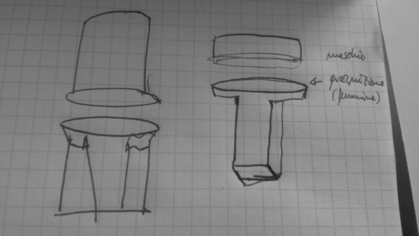
Adding a parallelepiped shape in the lower part of the container will make easier to do something that adhere to the container as much as possibile and that it is closer to the water.
This week I have too much images to resize one by one. I followed this page to resize multiple images
Resize Multiple images in a folder (Batch Image Resize) in Ubuntu
My SketchUP experience
I started using SkecthUP with simple shapes.
Here below some screenshot of the steps I followed with
SketchUP. They are
quite self-explanatory.
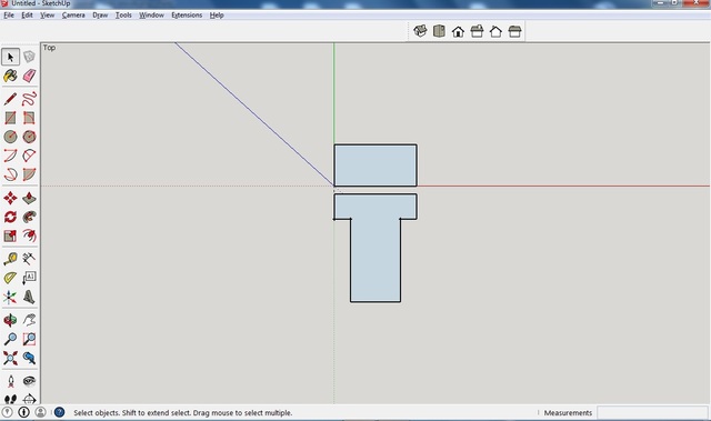
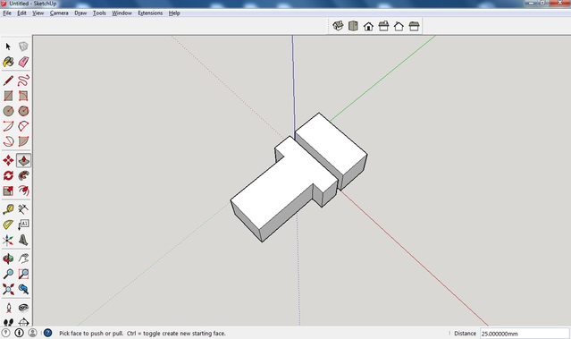
I did something simple with top view:
then I did the extrusion to have the idea of thickness
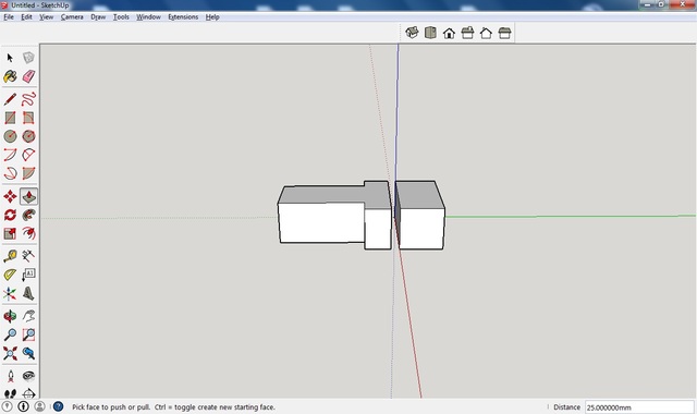
another view of the same object above
here below I added half-circle (extruded)
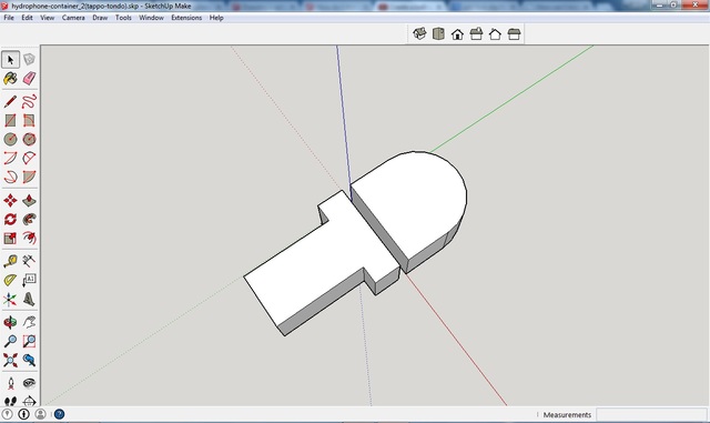
At this stage I realized I need to learn how to do a real hemispheric cap. I
discovered the “follow-me” tool in SketchUP and I liked it :)
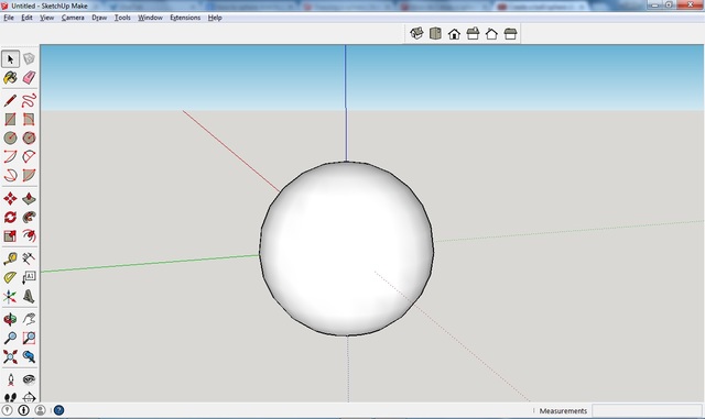
Following this quick tutorial I learnt how to do a sphere. I know, it looks a planet :)
.jpg)
Here it is a real sphere
First I did the container all rounded. Later I will do the lower part with
rectangular shape.
.jpg)
When I learnt follow-me tool better I did something more complex
using an arc and the tool. Thanks to my local instructor suggestion ;)
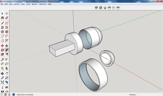
At this stage I learnt to give a thickness to my objects. You can see the cylinder below.
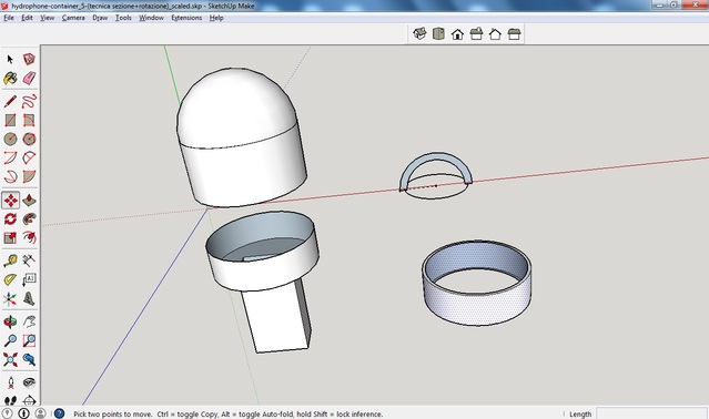
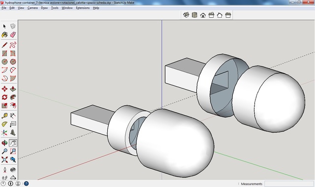
Below you can see the hemispheric cap with thickness. Here the cap is in two
pieces
Here the cap is in one piece
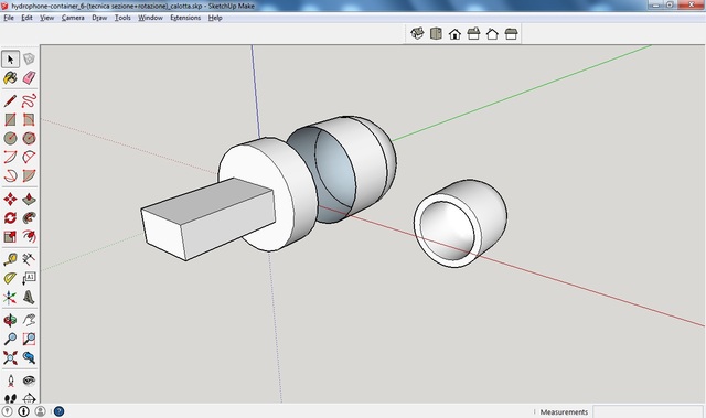
Here is the first piece of the lower part of the container.
You can always see the difference with the container without thickness in the
upper part of the figure.
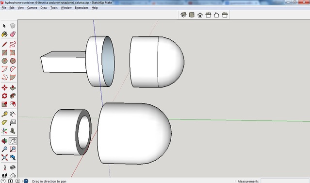
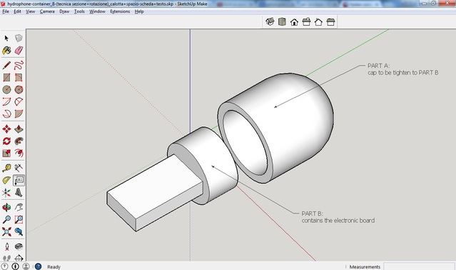
Here below you can see the final version of the container.
You can notice that in the lower part there is the area where I want to put my
electronic board.
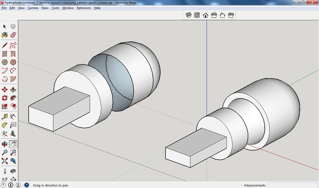
Here is the final version with text description.
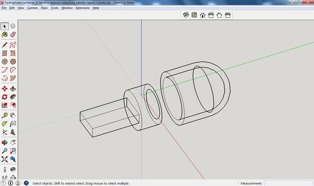
Another image where you can see inside the container with wireframe tool of
SketchUP
My OpenSCAD experience
Here it is my first step with openSCAD and the comparison with SketchUP.
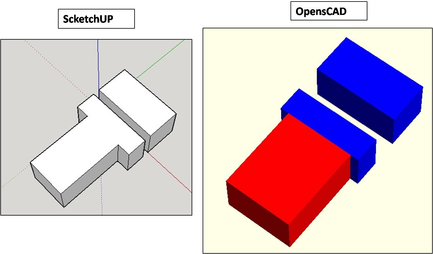
I like writing code and obtaining real 3D shapes :)
After the experience with SketchUP I feel more confident and after the first
image above I did directly the cylinder with some thickness.
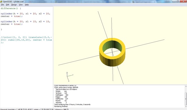
With openSCAD you can obtain a cylinder doing the difference between two
cylinders which have different radius.
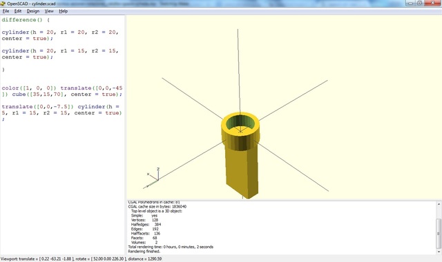
After this I added the PART B (the parallelepiped).
You can see that inside there is no area where I can put my electronic board. I
will do in the next steps.
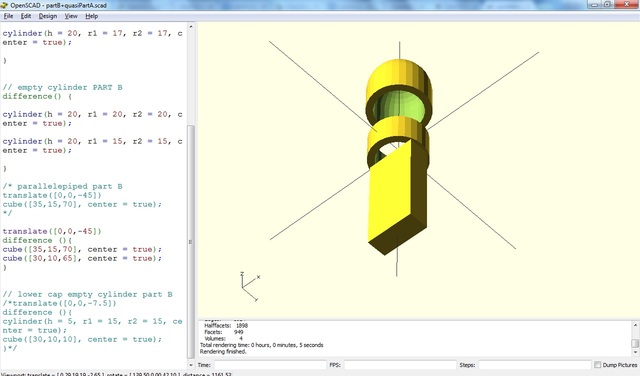
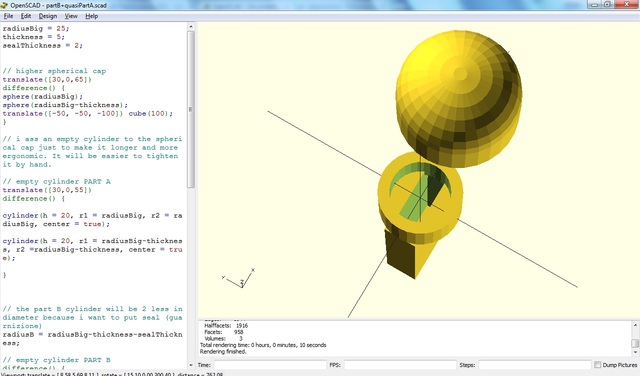
Here below I added the hemispheric cap. I did the hemisphere doing the
difference between two sphere with different radius and cutting the half of
the spheres with a big cube. Here you can notice an error because there is an
hole in part B. I solved it with something like a cap..a little cylinder
located at the base of the cylinder in part B. I know this is not an elegant
solution and maybe it could be a problem. I will remember it later.
Here is the code:
radiusBig = 25;
thickness = 5;

difference() {
sphere(radiusBig);
sphere(radiusBig-thickness);
translate([-50, -50, -100]) cube(100);
}
Here below you can see the container (PART A + PART B) almost complete BUT
there is no room inside for the electronic.
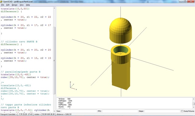
I did some space for the electronic inside the container :)
I used again the difference between two parallelepipeds.
My Antimony experience
I tried to install Antimony and it was
not so easy.
I am running Linux Mint 17.1 Rebecca and I followed the Linux
instructions
here
I found some problems after the make and here below I list the problems and
the solutions I found.
PROBLEM 1:
I had a problem of memory (I don’t remember the error message)
SOLUTION 1:
My local instructor suggested me to use simply make and not make -j8
PROBLEM 2:
fatal error: GL/gl.h: No such file or directory
SOLUTION 2:
sudo apt-get install mesa-common-dev
page where I found the solution
OR another solution I have NOT tested
PROBLEM 3:
/usr/bin/ld: cannot find -lGL collect2: error: ld returned 1 exit status
SOLUTION 3:
sudo apt-get install libglu1-mesa-dev -y
page where I found the solution
Project files
Here are the files of Sketchup and openSCAD.