Week 1 assignment
Principles and practices, project management (Jan 28)
Week 2 assignment
Computer-aided design (Feb 4)
Week 3 assignment
Computer-controlled cutting (Feb 11)
Week 4 assignment
Electronics production (Feb 18)
Week 5 assignment
3D scanning and printing (Feb 25)
Week 6 assignment
Electronics design (Mar 4)
Week 7 assignment
Embedded programming (Mar 11)
Week 8 assignment
Computer-controlled machining (Mar 18)
Week 9 assignment
Molding and casting (Mar 25)
Week 10 assignment
Input devices (Apr 8)
Week 11 assignment
Output devices (Apr 15)
Week 12 assignment
Composites (Apr 22)
Week 13 assignment
Networking and communications (Apr 29)
Week 14 assignment
Mechanical design, machine design (May 6)
Week 15 assignment
Interface and application programming (May 13)
Week 16 assignment
Applications and implications (May 20)
Week 17 assignment
Invention, intellectual property, and income (May 27)
Week 18 assignment
Project development (Jun 3)
Week 19 assignment
Project presentation (Jun 10)
Input devices (Apr 8)
This week I’d like to do an experience useful for my final project. I wanted to test a piezo as input device but we have to order them then I read that even a buzzer can be used as input device and I tested it. After a this (almost) successful test I designed a board to test the piezo we ordered.
Summary:
- Testing buzzer as input device with Arduino board
- Design new board
- Piezo test with multimeter
- Big mistake
- Test new board
- Conclusions
- Files
Testing buzzer as input device with Arduino board
Before designing the board, my local instructor suggested me to test if a buzzer can work as input device. I read this file and starting from page 11 you can read about using piezo as input device. I didn’t use the zener diode because I thought I won’t have big voltage for this test. I tried to test this example and it was (almost) successful.
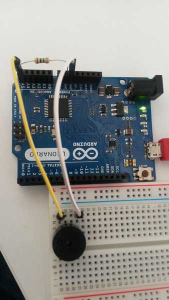
Below the simple code using Arduino IDE
#define knockSensor A5
int ledPin = 13;
byte val = 0;

int statePin = LOW;
int THRESHOLD = 10;

void setup() {

pinMode(ledPin, OUTPUT);
pinMode(knockSensor, INPUT);
Serial.begin(9600);

}


void loop() {

val = analogRead(knockSensor);  // read value from the pin
Serial.print("val = ");
Serial.println(val);			// print value using the serial

if (val >= THRESHOLD) {

	statePin = !statePin;		// turn on/off the led every time val >= THRESHOLD
	digitalWrite(ledPin, statePin);
	Serial.println("Knock!");

}

delay(100);  // we have to make a delay to avoid overloading the serial port

}
This code is a bit different from the code in the example in the link above for few reasons. First of all, my local instructor suggested me to use #define instead int for the pins. Moreover, in the example the pin was only with a number. I wanted to use the analogue pin and it is better using A5 instead of only 5. Furthermore (I don’t know why), in setup there wasn’t the declaration of the pin as input: pinMode(knockSensor, INPUT);.
The rest of the code is quite intuitive.
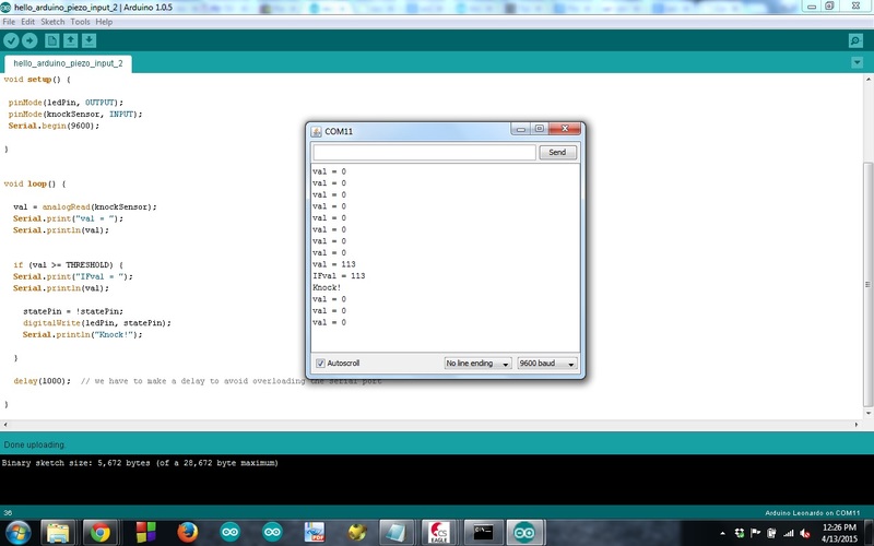
As you can see in the screenshot below the code works but I think that using the buzzer as input device you won’t have a sensitive sensor. I hope I will have something better with the piezo we ordered.
Design new board
I started with a big mistake. I wanted to use the same design of my Hello board with one button and one LED. I thought to remove the button and to add my piezo in the same pin. I designed, milled and soldered the components…only when I studied the code I realized that on pin where there was my button there wasn’t any ADC (Analog/Digital Converter). The ADC is essential to read the input signal of an analogue device, Lesson learnt!
This below is the wrong board with the wrong schematic
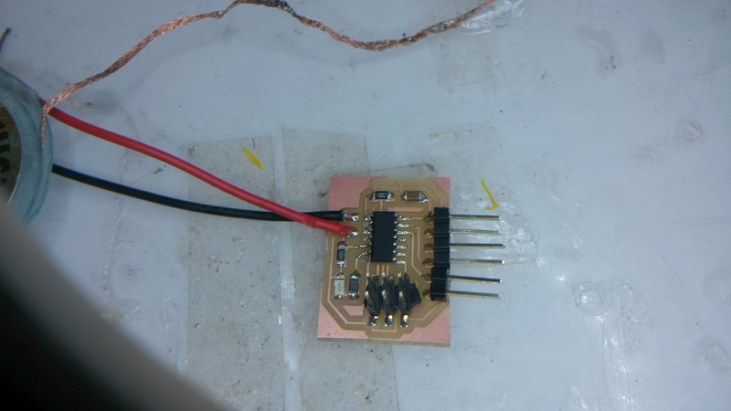
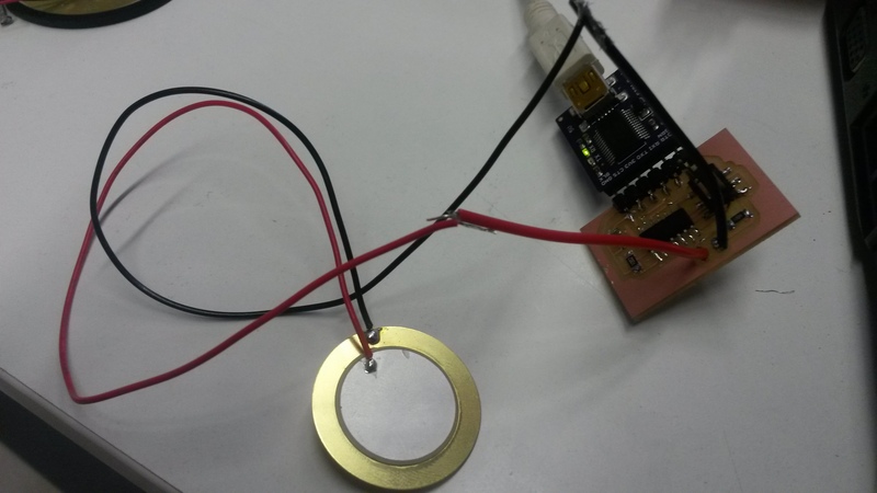
As a consequence I had to modify the board, I milled again the board and I desoldered the components from the old board to use them again in the new modified board. It was a good experience because now I feel more comfortable with solder and even using the hot gun. I learnt that the little components can be easily removed with the hot gun while for the connectors I had to use the copper braid. Finally here it is the simple board with two wires where I will connect various piezos to test them.
(image of right board and schematic)
Piezo test with multimeter
We ordered these piezo from RS
I tested one of them with multimeter to understand how the voltage varies. (link to the video) I set AC and I read 0 value if I don’t touch the piezo while I can read some values if I touch it. This last behaviour is what I expected. I read that AC setting on the multimeter gives me the RMS value.
Big mistake
Programming the board works but I did a big mistake.. I programmed fuses without having the resonator. This obliged me to remove the Attiny. In the beginning I was scared about this because I soldered all the components and furthermore I soldered the FTDI connector through holes and the board can’t be on a flat surface.
I started using the copper braid to remove the most of the tin and after this I used the hot gun and I removed the Attiny. Now it can be used only with a 20Mhz resonator. After that I soldered a new Attiny and I tried to load a program. Loading the program worked but now I have to understand how to program the board to read from a piezo.
Test new board
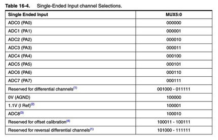
I started reading how to use ADC in Attiny44. There are two registers which are necessary are ADMUX and ADCSRA. I wanted to use ADC7 (PA7) then I have to write MUX5:0 = 000111 (see page.145 of datasheet)
With the line below I enabled the last 3 bits to set the pin where I want to use the ADC, that is PA7. You can also see the table on the datasheet.
ADMUX |= (1 << MUX2) | (1 << MUX1) | (1 << MUX0);
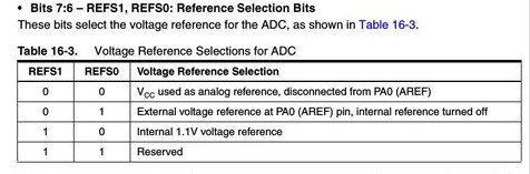
With these two lines
ADMUX &= ~(1 << REFS1);
ADMUX &= ~(1 << REFS0);
I set VCC as Vref for the comparator of the ADC as you can see from the datasheet table below
With the line below
ADCSRA |= (1 << ADPS2) | (1 << ADPS1) | (1 << ADEN);
I enabled three bits:
- ADEN sets the ADC Enable bit
- ADPS1 and ADPS2 are useful to set the prescaler at 1/64 because I want a sampling frequency of 125Khz and I have the Attiny at 8Mhz
Inside the loop (while(1)) I initiate conversion with line
ADCSRA |= (1 << ADSC);
The line below is useful to wait until the conversion is completed. The ADSC bit is cleared when the conversion is over.
while (ADCSRA & (1 << ADSC));
In the end we save the 10 bits of the ADC in two 8 bit registers: ADCL, ADCH. L is low and H is high. The 10 bits are divided in two parts.
array_lo[i] = ADCL;
array_hi[i] = ADCH;
After that we write all in serial port to display it.
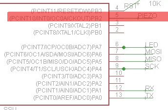
I also discovered only now that I used the serial port that I did and error in my board. I inverted TX and TX in FTDI as you can see below in the schematic. I had to connect TX from the Attiny to RX of FTDI and RX from the Attiny to TX in FTDI.
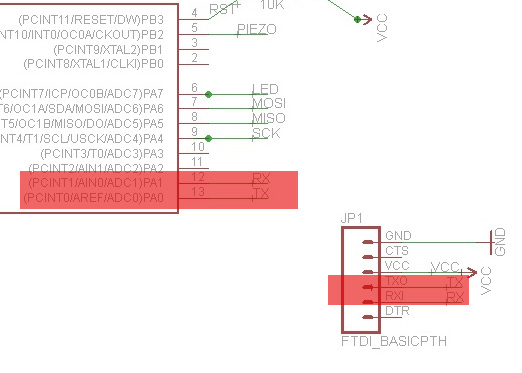
For this reason I had to put the serial pin output in PA1
#define serial_pin_out (1 << PA1) // TX pin
In the end I used the python script from the lesson webpage (the mic example) to display the values read by ADC
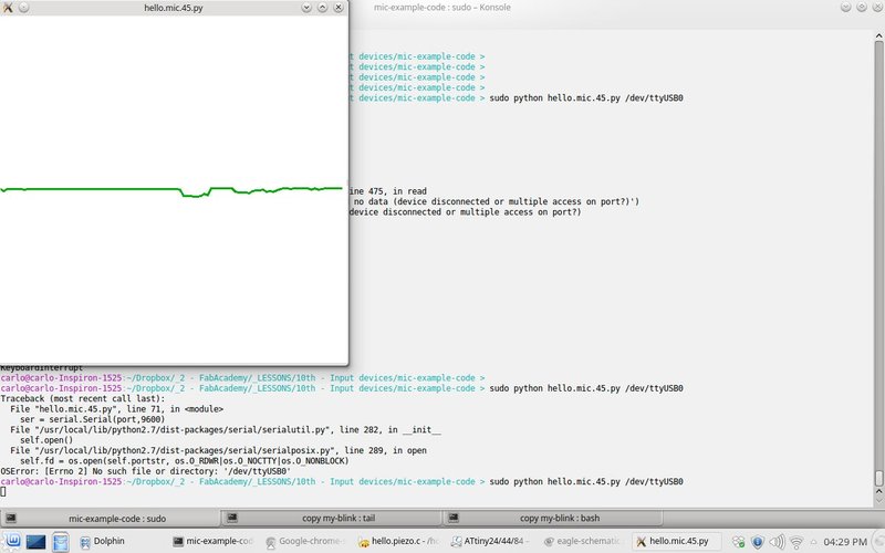
using this simple connection:
Conclusions
I like electronics but it really needs a lot of patience. This week I understood how ADC works and I also did many errors but they are useful to learn and remember what I have NOT to do :) I also fixed the board error I did in FTDI connector and this was useful to store in my mind how FTDI works. In the end, I also understood that I have to do a little change to the schematic according to this image below
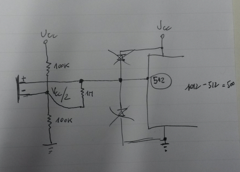
The reason is that ADC reads only positive values while if I want to read also negative values from the piezo I need to do in such a way that when I don’t touch the piezo I want to read the midpoint (512) of the range of values that ADC can give me. We have a 10bit ADC then the range will be from 0 to 1023 (2^10 - 1). In this way I will have to subtract 512 every time I read a value from the ADC and I will have positive and negative values. Thanks to Stefano Panichi for the explanation :)
Files
Here are the files. You can find:
- the PNG files to be milled
- C code files
- Eagle schematic and board