Week 1 assignment
Principles and practices, project management (Jan 28)
Week 2 assignment
Computer-aided design (Feb 4)
Week 3 assignment
Computer-controlled cutting (Feb 11)
Week 4 assignment
Electronics production (Feb 18)
Week 5 assignment
3D scanning and printing (Feb 25)
Week 6 assignment
Electronics design (Mar 4)
Week 7 assignment
Embedded programming (Mar 11)
Week 8 assignment
Computer-controlled machining (Mar 18)
Week 9 assignment
Molding and casting (Mar 25)
Week 10 assignment
Input devices (Apr 8)
Week 11 assignment
Output devices (Apr 15)
Week 12 assignment
Composites (Apr 22)
Week 13 assignment
Networking and communications (Apr 29)
Week 14 assignment
Mechanical design, machine design (May 6)
Week 15 assignment
Interface and application programming (May 13)
Week 16 assignment
Applications and implications (May 20)
Week 17 assignment
Invention, intellectual property, and income (May 27)
Week 18 assignment
Project development (Jun 3)
Week 19 assignment
Project presentation (Jun 10)
Electronics production (Feb 18)
Summary:
This week was a good week! I thought that soldering SMD electronic components
was more difficult but in the end everything works at the first attempt. My
local instructor told me that it was a stroke of luck :) In the past I had a
little experience with the solderer but I never soldered SMD electronic
components. I liked the sequence of teaching first the production and after the
design of electronic. I think that when you put your hands on then you will be
more motivated to design. I mean that when you design and you haven’t ever seen
anything of electronic components, you haven’t ever put your hands on the
solderer and the electronic components, you will be quite bored to pay
attention when someone explains to you something that is very tangible and you
have never seen it. I think that it could be even frustrating. Obviously I am
talking about my academic experience when I studied always
on books and if you were lucky you colud use a computer simulator. Anyway,
this week we have to product hte FabISP key which will be very useful to
program the Attiny microcontroller without buying any other (expensive)
electronic device. Here below my weekly report.
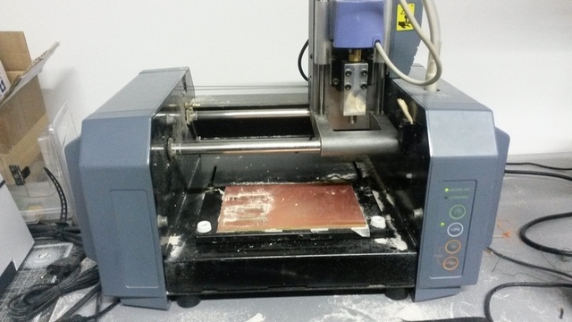
Milling machine
Here it is the Roland MDX-20 milling machine at our Fablab. You can see the copper plate ready to be etched.
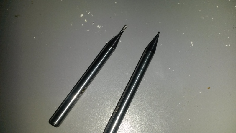
There are two end mills we used: the one on the right was used to etch and the one on the left was used to drill.
The first thing you have to do is to learn how to change the end mill. There is
a very little screw and a little wrench to do it. You need patience and you
have to be very careful because you can easily break the tip of the end mill.
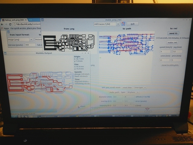
After you put the 1/64 end mill you can disable the view mode on the
Roland then you have to lower the tip with up/down buttons in such a way that
the tip can go about one centimeter down (one centimeter of stroke). Now you
can send the coordinates to the milling machine using the fabmodule panel. You
can see xmin and ymin below. I took the picture when the machine was
working, I’ll explain it better below.
After you send the coordinates you have to lower the tip until it touches the
copper base. In this way you give the zero to the z axis.
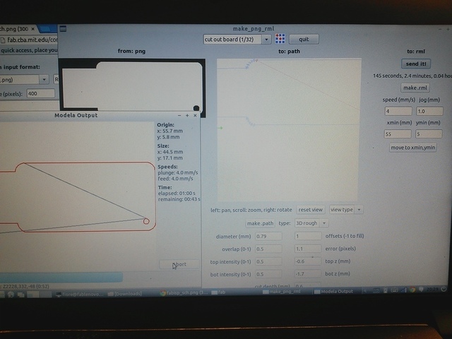
Now we can better describe the fabmodule panel. First of all you have to select
the right end mill from the drop down menu. You can see mill traces 1/64 in
the top center of the picture. When you select it, many parameters are
loaded and you can see them in the bottom of the picture. Above all you can
see z(mm) that is 0.1mm. This is how much the tip will go down to etch the
copper base. Afterwards you have to load the picture of the circuit. As I wrote
in the first lines of this page, this week the assignment is electronic
production then we have a ready picture to load. The picture of the circuit is
the one in black and white in fabmodule panel. You can see a detailed
picture here
All you can see in black will be etched. After a quick check to
the parameters (we didn’t modify anything) you have to click on:
1. make path
2. make .rml
3. send it
Before you click on send it you can check (on the right side of the
fabmodule panel) if the created paths cross each other. You can zoom as much as
you want. After these steps the last thing before the start of the process is
clicking on the Begin milling button and…you can see in the
video what will happen. You can also follow the
etching process in the fabmodule panel. The red line is updated to show you
what is going to be etched.
When the milling machine starts, what you have to check is that white dust you can also see in the picture below
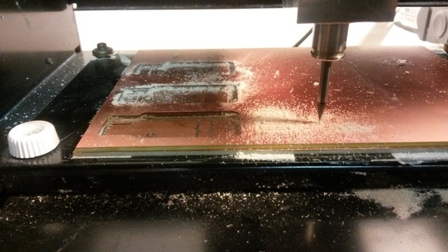
You also have to pay attention to the sound of the milling machine while it is
working. If you hear some strange sounds maybe that when you set the tip or
when you set the copper base you did something wrong. When you set the tip you
haven’t to press too much on the copper base. When you set the copper base you
have to do in such a way that it has to be perfectly horizontal. If you do
something wrong you could hear some strange noises and it is better you stop
the milling machine and you check everything again. The white dust without
strange noises is a good way to confirm that you did everything in the right
way.
After all, I changed the end mill with the 1/32 one in order to drill the
copper. Here below there is a similar screenshot of the fabmodule panel.
Obviously you have to load the other picture and you have to change the
selection in the drop down menu with 1/32. You can notice that now the bot
z(mm) is -1.7mm which means that the tip will go lower and it will drill the
copper base.
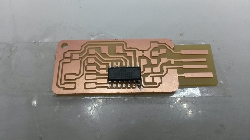
At the end of this process with the milling machine I producted this
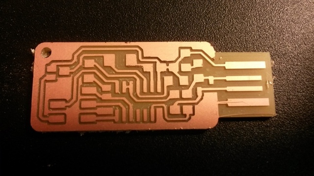
In the picture above you can notice little imperfections. For example on the right end of the key you can see little pieces of copper. It is better to remove them to be sure that when you will use the key everything works fine. This little pieces of copper can create short-circuits.
Soldering
Let’s start with soldering stage. First of all, as my local instructor suggested, I read this fun and short book Soldering it’s easier than you think. It was interesting but it shows you nearly the same suggestions Neil gave use during the lesson.
This is our soldering station
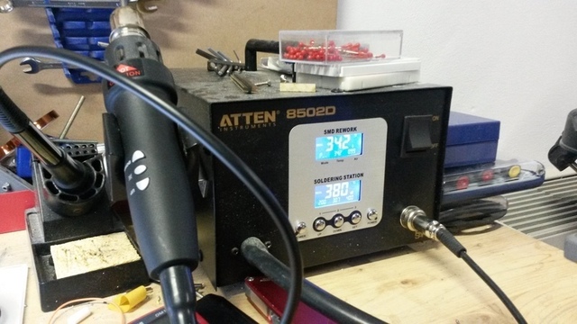
There is also the hot air gun to desolder. I never used it before and I was a little scared, but it was very useful because I did some errors..
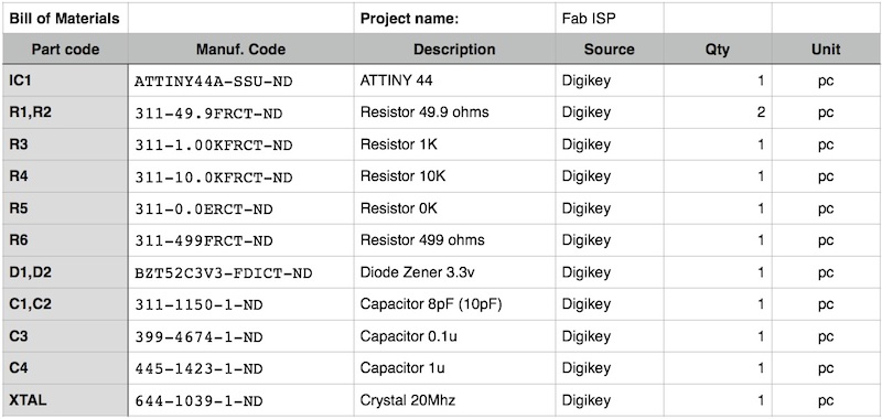
I used the BOM (Bill Of Materials) in my local instructor page
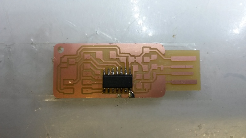
The first thing to solder is the microcontroller. Following Neil’s
advices (which are the same of the book) you have to put some tin on
the copper and then you put the microcontroller on it. In this way the micro
will not move when you will solder the rest of the pins.
Here is a picture where you can see the first pin fixed.
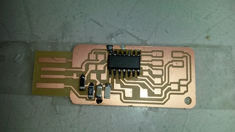
Afterwards, with a lot of patience, i soldered the other pins. You can notice too much tin on the first pin because you have to solder the first pin again after all the others. I was not so good with the first pin.
In order to verify the connection I used the tester (unfortunately I haven’t the picture here) and this picture.
Here is my first error! In this page was looking at this image which was related to FabISPlokey then i soldered the wrong capacitor. Where i have to solder C4 I soldered C1. The wrong capacitor is the white one below. The right image to follow is this one
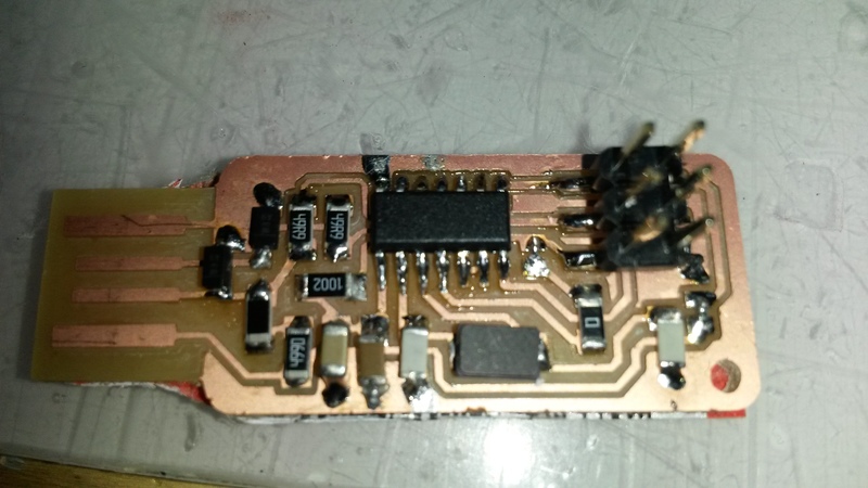
What a perfect opportunity to use hot air gun! With the hot air gun you have to be really careful to your hands! I desoldered the capacitor without harming myself and I continued to solder the other components. In the end I soldered everything but I did another (undocumented) error. I solder the diode in the wrong way. The diode has a very little line to specify which is the cathode. I knew it but distracted and I soldered it in the wrong way. Another great oppportunity to use the hot air gun! :) Finally, here is my FabISP key!
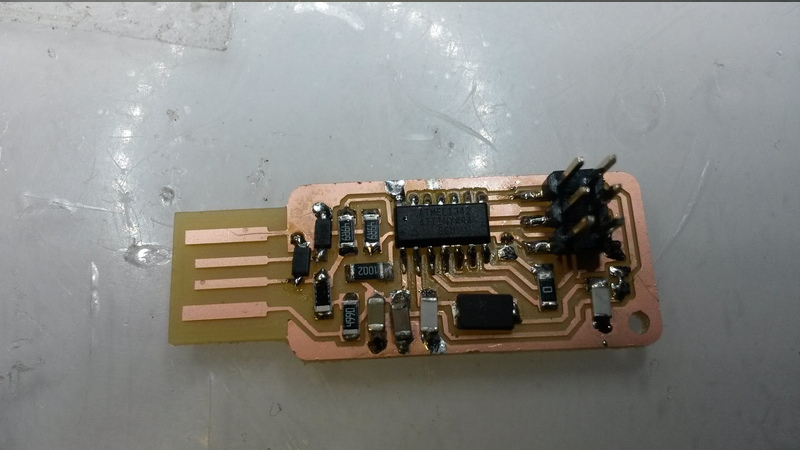
In order to have the right thickness to connect it to the USB port I cut and added a piece of an old credit card.
The last step is to program the FabISP. You can use another FabISP key or some other commercial devices. You have to connect the FabISP key to the other one and following the last lines of the assignment page you can easily program it IF you were lucky (like me) and you soldered everything in the right way. The steps to program the FabISP are:
- download and extract the firmware
- go inside the directory
make cleanmake hex(to compile and create the .hex file)sudo make fuse(to set some register values)sudo make flash(to load the .hex file on the micro)
If you use sudo make program you will do bot fuse and flash.
After programming the micro you can desolder J1. See this image again.
Conclusions
I really enjoyed to product this little key. I always wanted to learn to make an electronic device from scracth. Now, what I need is to learn how to design a board. I can wait few weeks :)