Week 1 assignment
Principles and practices, project management (Jan 28)
Week 2 assignment
Computer-aided design (Feb 4)
Week 3 assignment
Computer-controlled cutting (Feb 11)
Week 4 assignment
Electronics production (Feb 18)
Week 5 assignment
3D scanning and printing (Feb 25)
Week 6 assignment
Electronics design (Mar 4)
Week 7 assignment
Embedded programming (Mar 11)
Week 8 assignment
Computer-controlled machining (Mar 18)
Week 9 assignment
Molding and casting (Mar 25)
Week 10 assignment
Input devices (Apr 8)
Week 11 assignment
Output devices (Apr 15)
Week 12 assignment
Composites (Apr 22)
Week 13 assignment
Networking and communications (Apr 29)
Week 14 assignment
Mechanical design, machine design (May 6)
Week 15 assignment
Interface and application programming (May 13)
Week 16 assignment
Applications and implications (May 20)
Week 17 assignment
Invention, intellectual property, and income (May 27)
Week 18 assignment
Project development (Jun 3)
Week 19 assignment
Project presentation (Jun 10)
3D scanning and printing (Feb 25)
This week we have two assignments. First one is 3D modelling and printing an object which could not be made subtractively. Second one is 3D scanning an object.
Summary:
My 3D printing experience
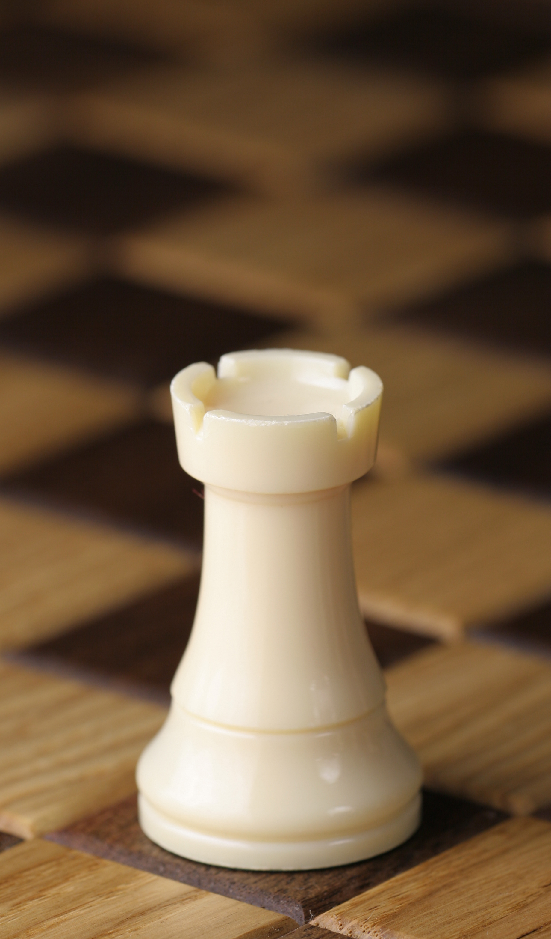
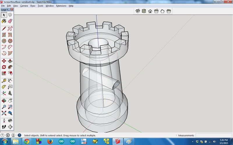
I have to do more experience with 3D modelling. This assignment is a good opportunity because I am not so skilled with it. First of all I had to understand what means that an object could not be made subtractively. It is not so intuitive for me. In the end, with the help of my local instructor I decided to do a chess piece: the tower or the castle or the rook. I found many names for this object. Anyway, it is this one below.
I chose Sketchup because, even if I used it only few times, I feel more comfortable with it and the rook looks something feasible according to my skills and the time I have to do it ( project management lesson ;) ).
I followed this italian tutorial for the tower. In order to do something which could not be made subtractively, my local instructor suggested me to add an horizontal tunnel and a vertical hole.
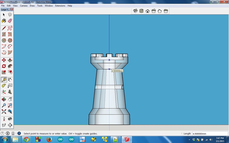
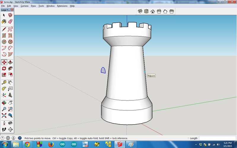
Drawing the tower was quite easy thanks to the tutorial and I learnt how to use the protractor with Skecthup. On the other hand, doing the holes was not so easy. The vertical hole was the easiest one, once I measured the height from the top till the point where I need. In order to measure the height, “parallel projection” from the “camera” menu was very helpful. You can see the picture below.
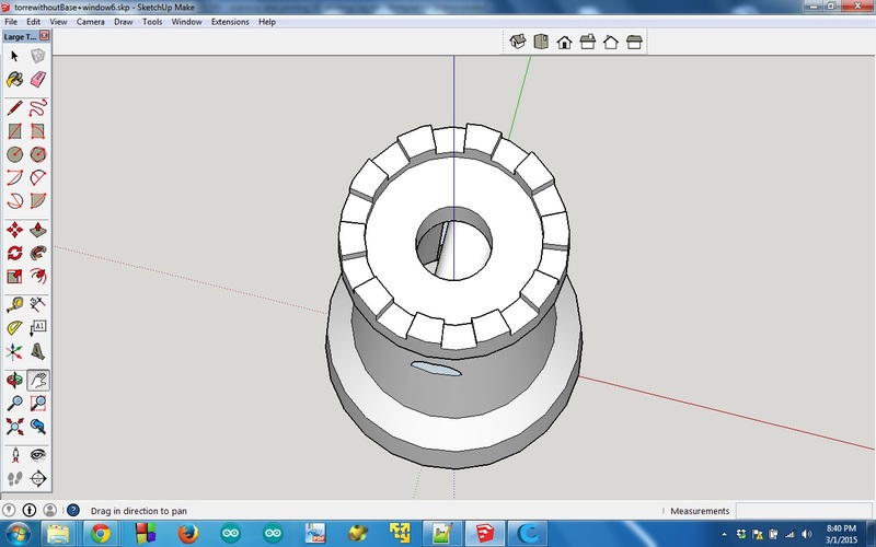
I did a circle on the top of the tower and I intruded it according to the measure. Then
I delete the last surface (obviously a circle).
Here below you can see a view of the hole from the top.
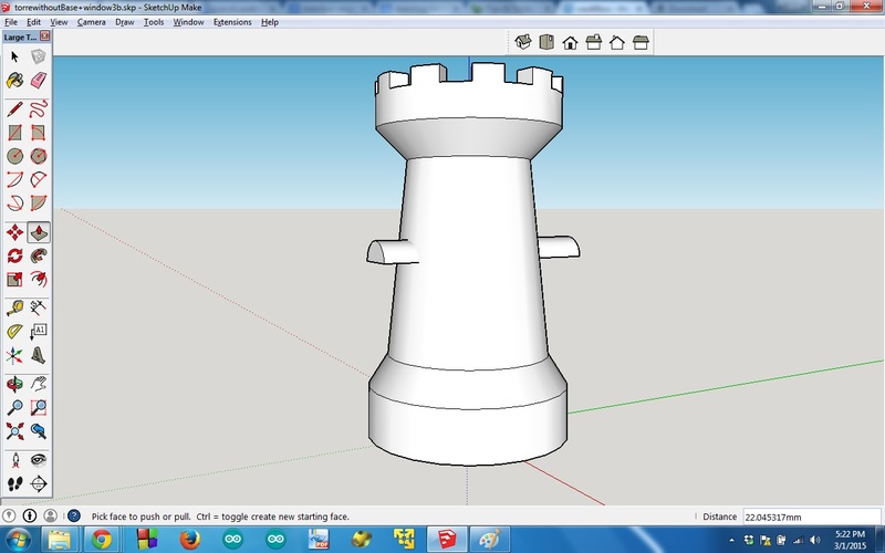
The horizontal line was more difficult. I was trying to project a shape onto a curve surface but I didn’t understand how to do it. My local instructor suggested me to do a shape and then using “intersect faces” (with the model) from the “Edit” menu. First I tried to use a shape which was the union of a semi-circle and a rectangle, that is something like a door. This shape was difficult to intersect with the model because that little line you can see on the side create some problems when I intersect it with the model.
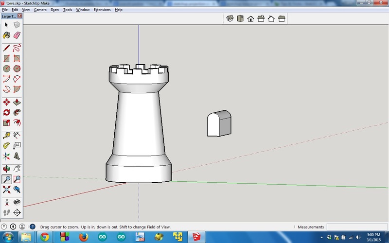
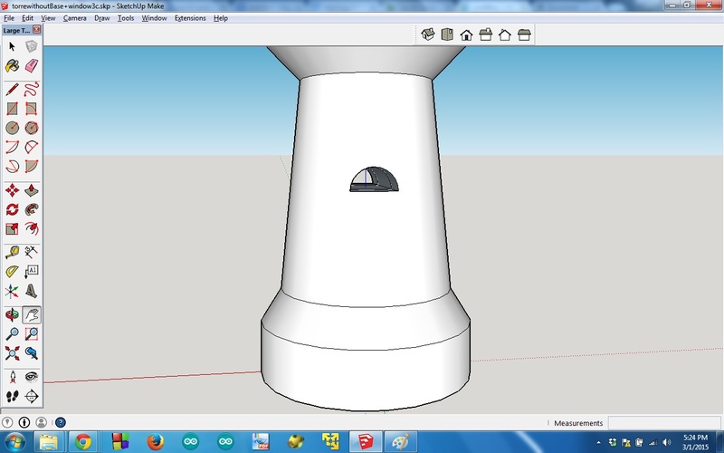
I did something better extruding a simple semi-circle.
I intersected it with the model.
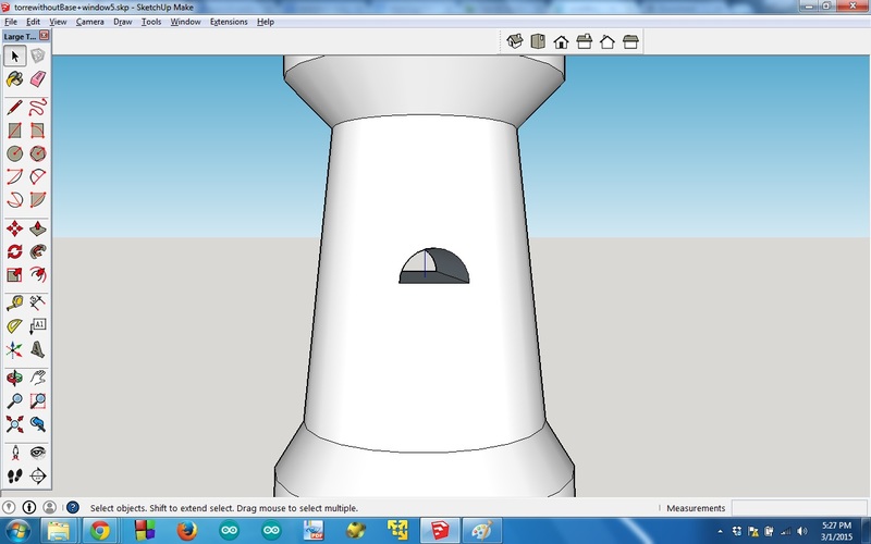
Afterwards I selected and deleted all unnecessary surfaces and lines you can see in the picture below.
In the end, as you can see below, I obtained a clean hole. It is something like a tunnel.
Using X-ray view you can easily see the tunnel inside the tower.
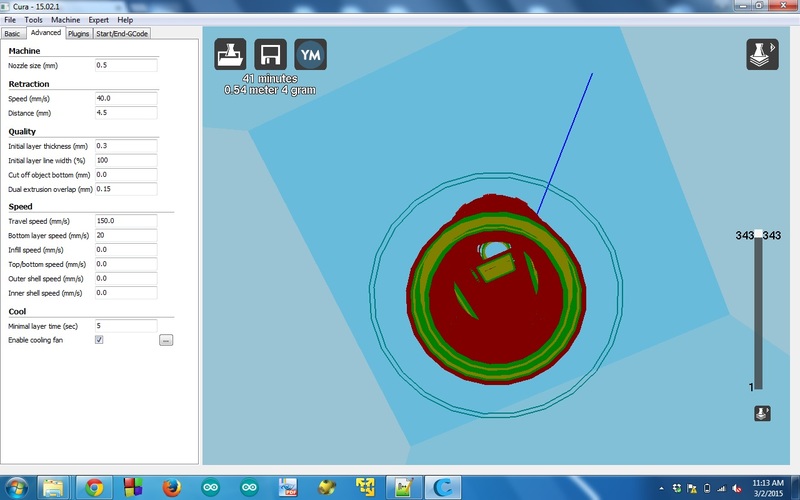
In order to print the model I had to export it in .stl format. This format can be opened with a slicer program like Cura. After I opened the .stl file I needed to scale the model because I did it too little. Scaling is very simple because you have to set only the height (z axis) of your object and the other dimensions (x and y axis) were automatically resized. My instructor had already adjusted the settings for the specific printer then the only thing that I had to do was choosing the right “machine” from the menu. In the end I had a .gcode file which is the language that the printer understands. I copied this file into SD card and I inserted it in the 3D printer below.
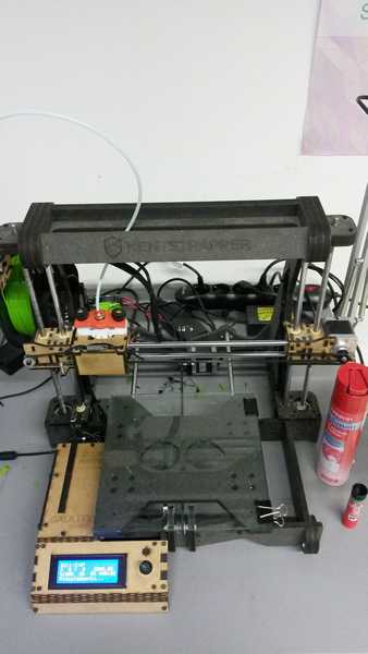
Before starting to print it is better to put some hair spray on the printer plate. This is useful in the end when you have to detach your object from the plate. In the beginning the printer had some technical problems, that is the extruder was occluded. Thanks to my local instructor the problem was solved.
First printing attempt was unlucky.
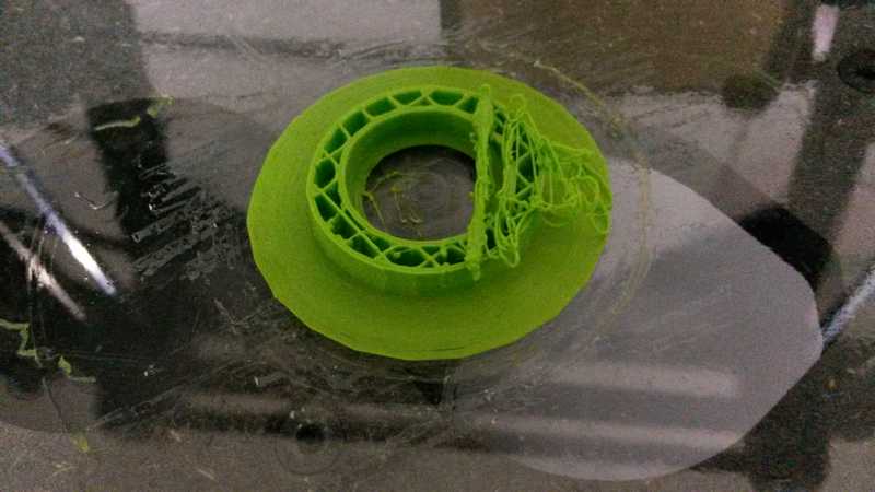
Second attempt was better, but not so good. You can see that this time the printer was printing in the right way.
However the window was not printed very well.
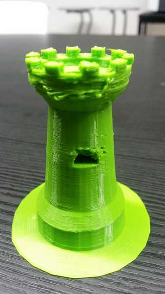
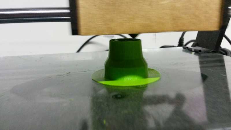
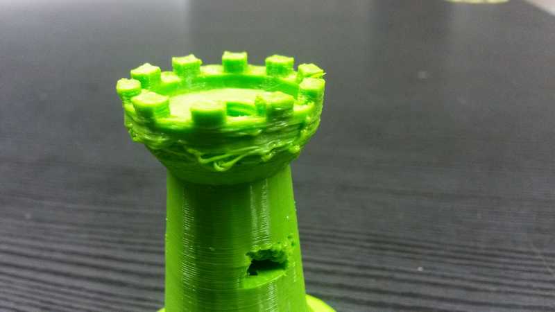
Here below you can also see that the top of the tower, where the printer has no base to put the material on, it was more difficult to print and maybe it is better to print slower in order to let a better material consolidation.
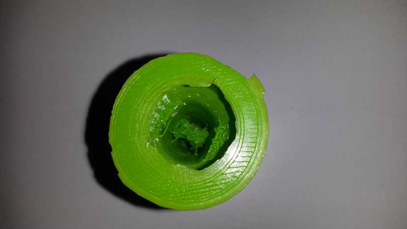
Here below there is a bottom view to let you see how the tunnel was printed. Even this part is difficult to print because there is no support below the tunnel.
As you can understand I need to do more practice with 3D printing. I’d like to try something where I need supports which will be removed in the end. This week the time is over, but I’ll try again next weeks.
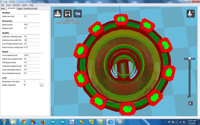
I didn’t understand why there is no hole on top.
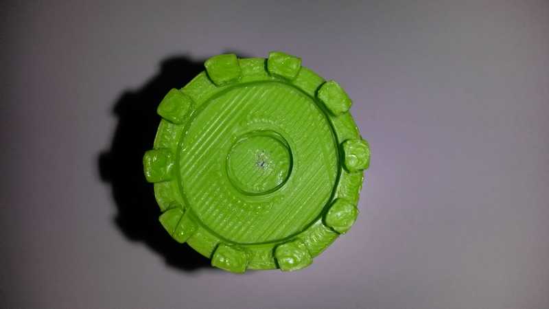
In the second picture of Skecthup in this page you can see that it looks I drew the hole correctly. I also checked the top hole in Cura as you can see below in the screenshots and in the layering video I did.
In the end, I am not so satisfied, but this is a nice first step. I think I have to go in depth to understand how to print something that has no support below like when you print following a plane with a slope. In this case, I understood that a good 3D printing depends on how much is the slope. If there is too much slope the software which does the slicing can calculate supports you need. These supports will be printed and at the end of printing you have to remove them.
My 3D scanning experience
When you want to have a digital model of an object or something bigger and you don’t want to model it from scratch you can use 3D scanning techniques.
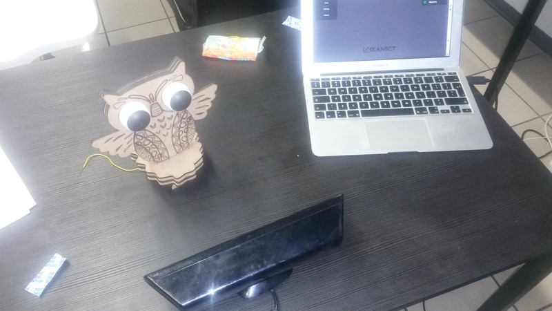
I decided to use Kinect and Skanect to scan an object. Scanning an object it is more difficult than scanning a human body. I chose an object we have at Fablab, the owl :)
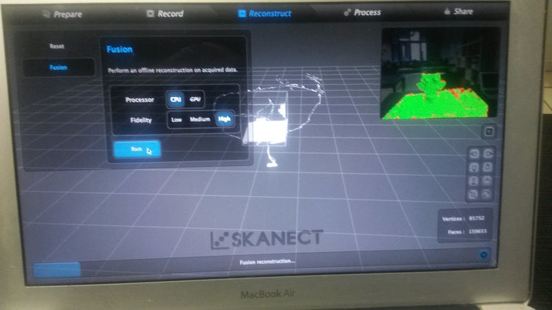
Using Skanect is quite intuitive. In Prepare tab you choose what you want to scan, that is body, object etc and when you confirm you will have some settings according to what you chose. You can modify these settings but I chose not modifying the scanning area, a cube 0.6 meters. This is the area that the Kinect will consider to scan. You have to do in such a way that your object has to stay inside this imaginary cube. The other objects outside this area will be ignored. In Record tab you have click on the red button to start the real scanning process. This stage is not so easy because you have to turn around your object while you watch on the laptop with the Kinect connected with usb cable. It is important to keep Kinect pointed to your object while you turn around. Moreover you haven’t to forget to scan your object also from the top and from the bottom. In the end I got what you can see in the picture below.
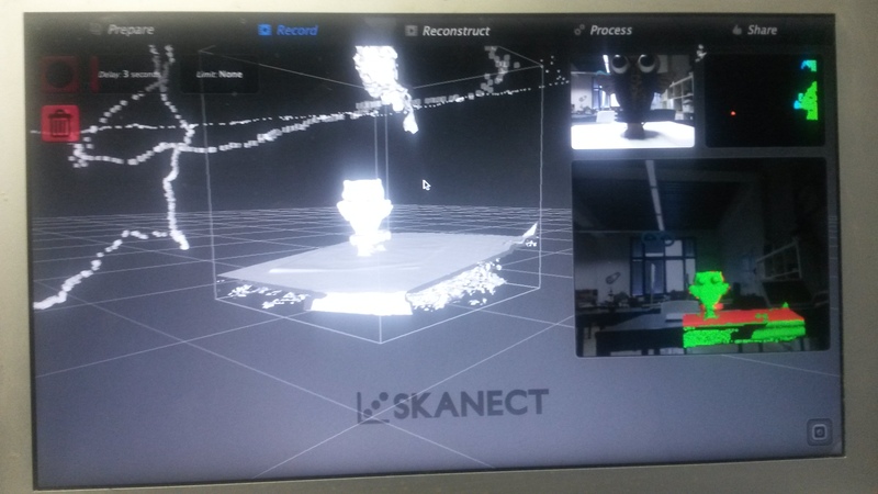
You can see that also the table was scanned. Moreover the whole figure was on sloping plane.
After this stage you can go to the Reconstruct tab where you can do an offline processing. It takes few minutes.
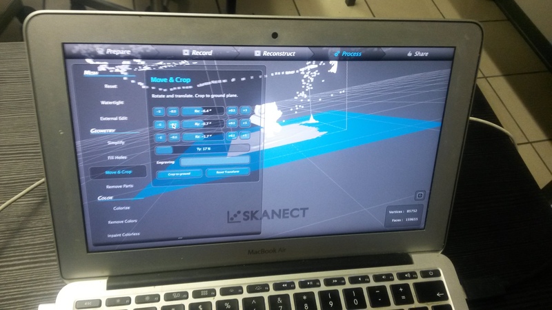
After this stage you can use Move & Crop to straighten the whole figure. You can also remove some little parts which were scanned but you don’t want them. Using Remove parts Skanect can identify those little parts which are in percentage more little compared to your object. Now you can use Fill holes function to water tight your object. This is a function which helps you to process your object in such a way that it will have no holes. After the processing you can verify it. If you imagine you’d like to put some water inside your object you cannot do it.
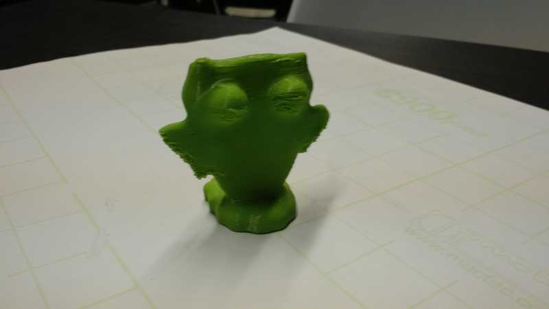
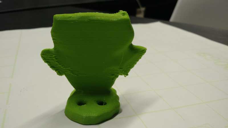
In the end you have to export your model using again .stl file format. Using Cura again I scaled the object with an height of 8cm and I saved the .gcode file. Before printing the file, my local instructor gave me a trick according to our 3D printer. In our printer there is a little fan only on one side of the object. My local instructor decided to rotate the owl in such a way that the front of the owl (that is the most difficult part to print because of the eyes) will be in front of the fan. This could improve the printing process because the material can quickly solidify itself before falling down. You can see the printing result here below.
Conclusions
I am not so satisfied with my 3D modelling skills, I need to do more practice. Anyway, I like 3D printing even if it is a bit stressful understanding all the tricks and techniques to print a beautiful object as you modelled it. I also like 3D scanning even if I did it only with Kinect. It is quite magic how this technique can reconstruct an object or even a human body shape in few minutes. I hope I can also partecipate to build our own 3D scanner to go in depth with other 3D scanning techniques.
Project files
Here are the files. You can find the .stl file of the owl, the model I did with Sketchup and the corresponding .stl file.