Electronic Design
For this week in Electronic Design,Hello world board desinged in Eagle PCB design software.Following are the steps I did.
Step 1: Downloaded Eagle PCB design software from here.Installation done.
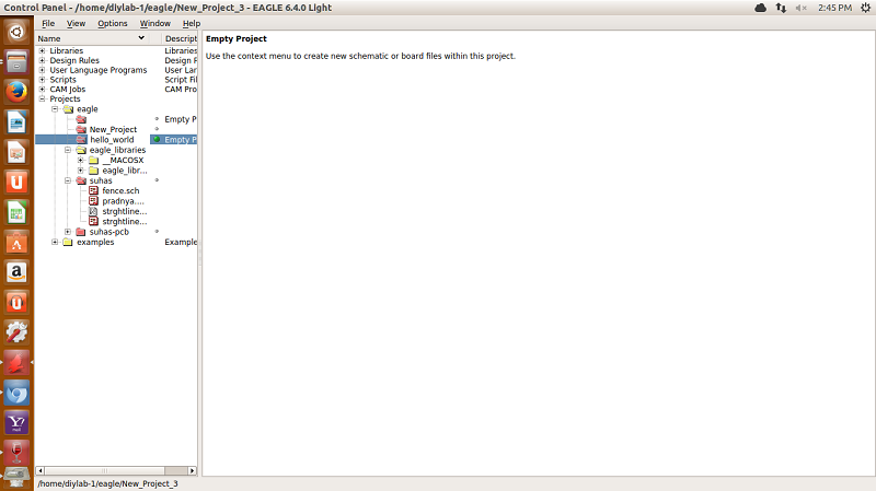
Step 2: After this open Eagle window. Click on File--> New--> Project-->Give project Name (here 'hello world'). Save project. Refer fig.1
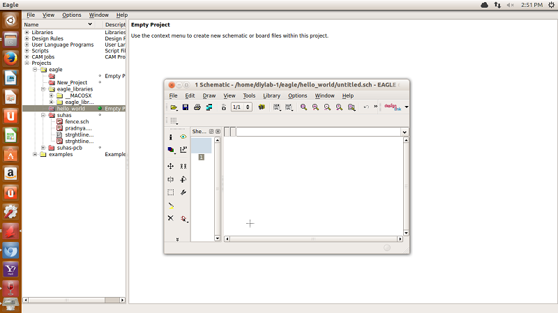
Step 3: Right click on Project name -->New-->Schematic .New schematic window will open.
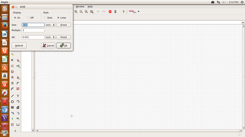
Step 4 : Inside schematic window EAGLE uses a layout grid to make it easy to align components.Turn on grid; selected size:0.05 and alt: 0.025.
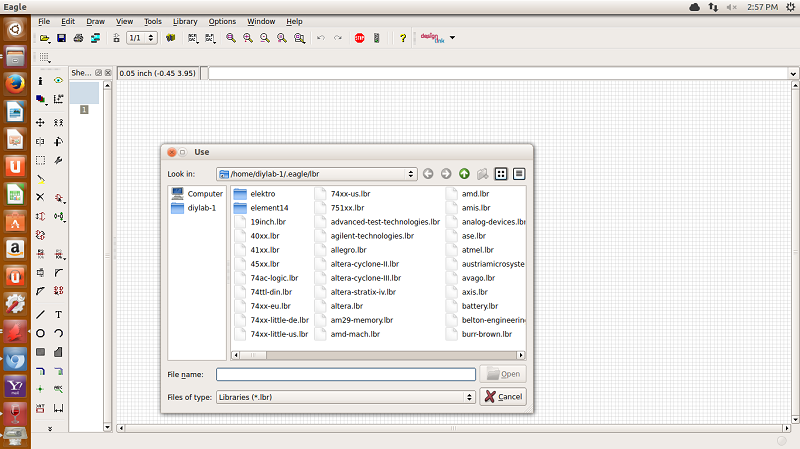
STep 5: Download and add Eagle libraries inside using 'USE'command.Adding of fab.lbr showing below.
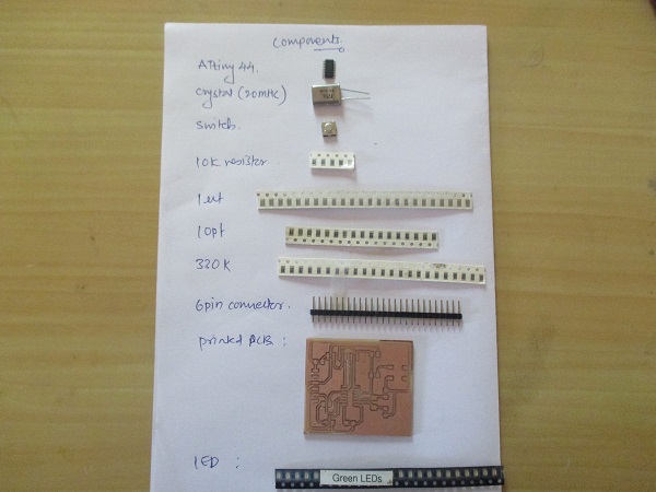
Step 6:Drawn rough schematic on paper and listed out components as follows :
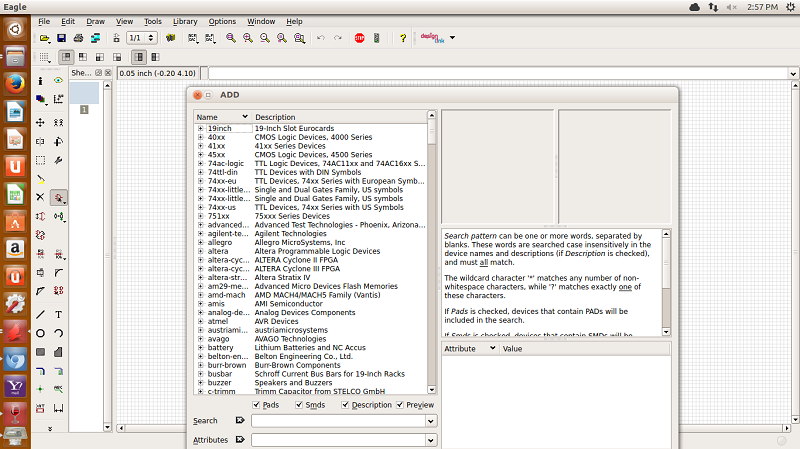
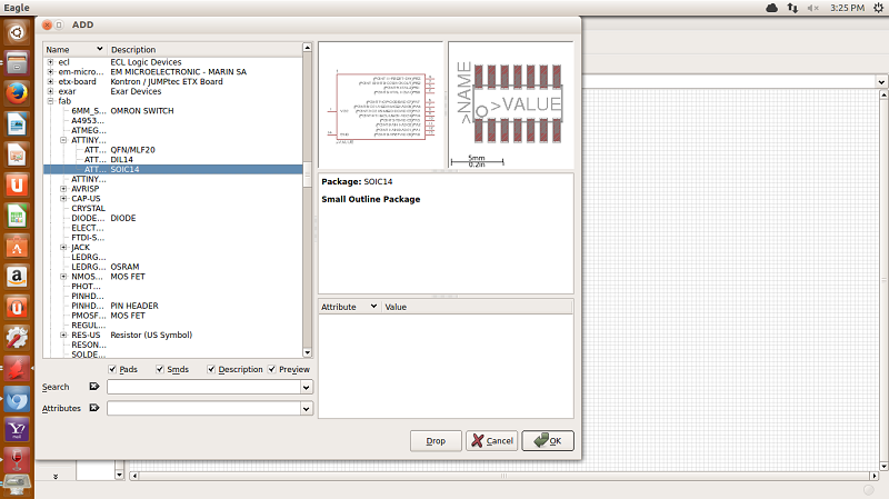
Step 7: To add components use 'Add' command ;following window will appeare containing libraries with components. select desired package of required components and place it.
 .
.
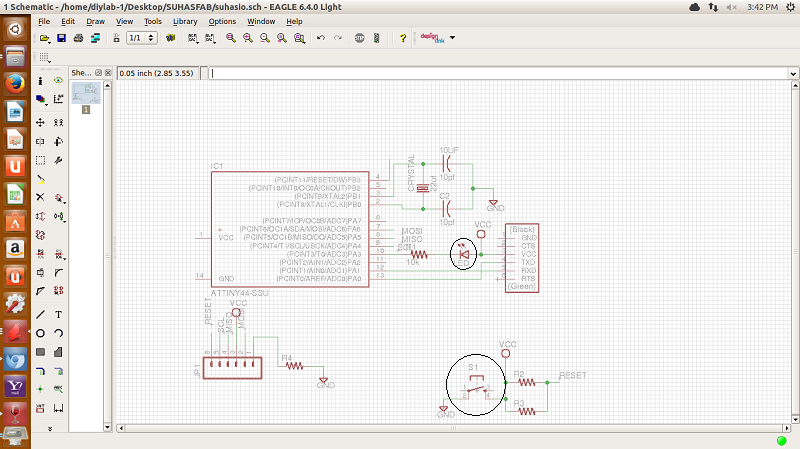
Here I have added LED and switch inside hello world schematic.
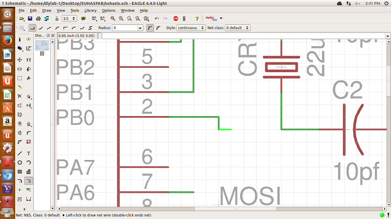
Step 8: Using add ,delete,move,Name , Value, Rotate commands placed components.Wired together with 'net'command.
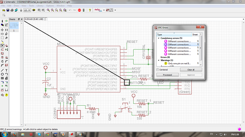
Step 9: Check under Tools-->'ERC'(Electrical rule check).Remove errors .
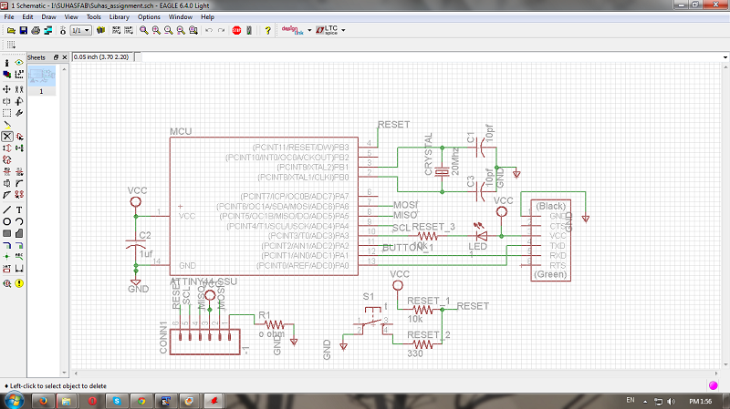
Step 10: Final schematic.
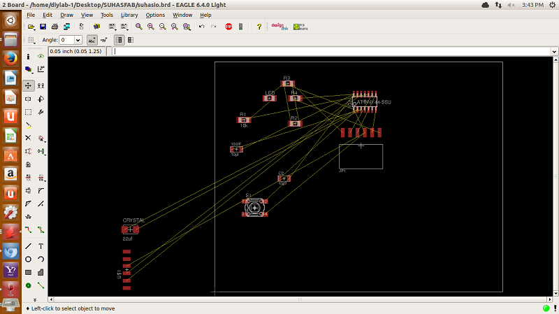
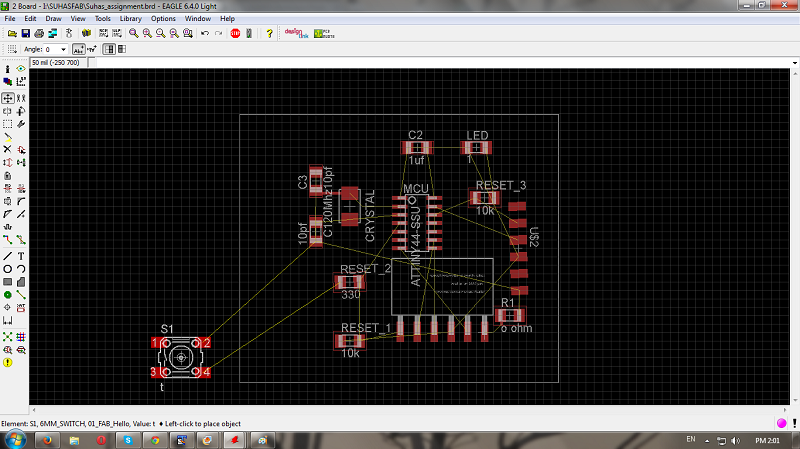
Step 11: Now switch to actual board design with clicking on 'switch to board'.Have to move components outside border to inside with running 'move 'command.
Step 12:Adjust components as per feasible for routing and checking with design rules.
step 13: Using Move , Rotate , Rip, locate component packages.
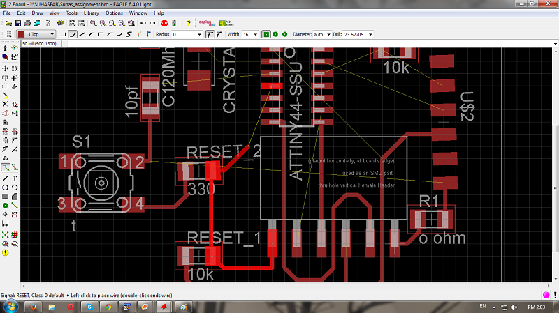
Step 14: Now start routing with executing 'route' command.There is also 'autoroute'option ;But I preffered it manually.Select track width with 'change' command.
Step 15: Check 'DRC'(Design rule check) and remove errors.
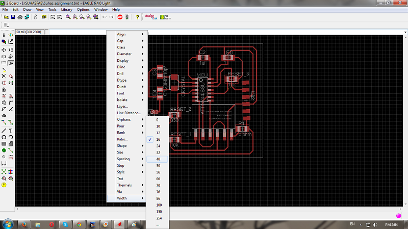
Step 16: Change board dimensions with moving a border.Change width to '40' using 'change' command.
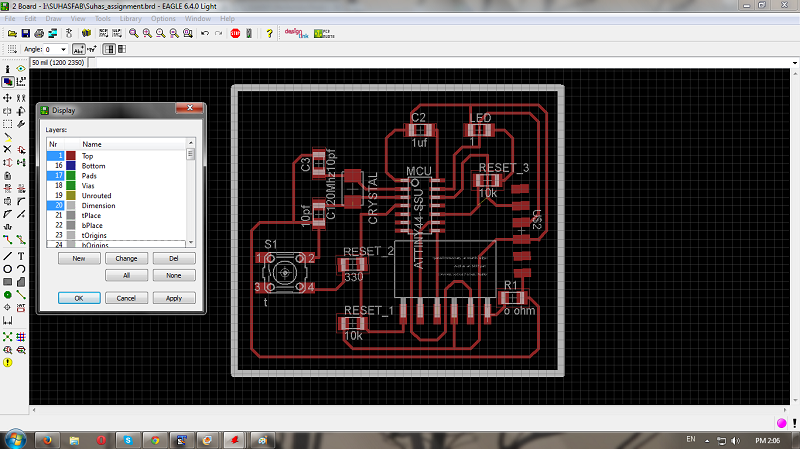
Step 17: Now open Layer setting select parameters those required.
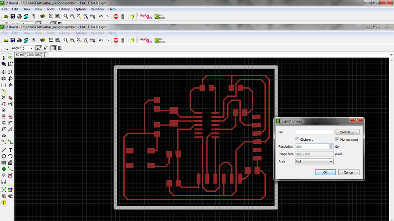
step 18: Go inside File -->Export--> Image-->select Monochrome-->set resolution 500 dpi-->save it.
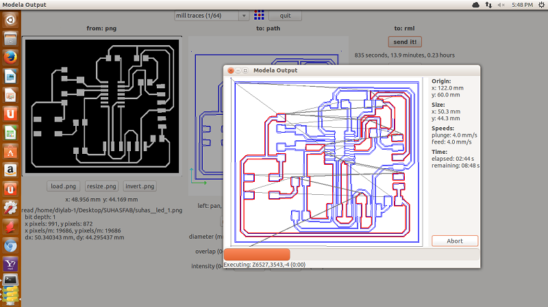
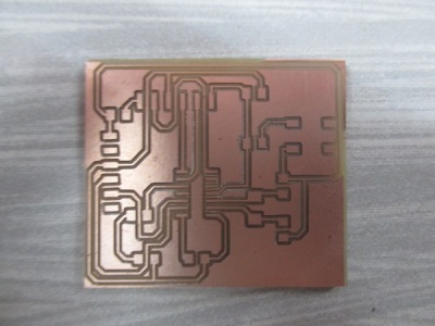
Step 20: Done modella machine setting and Imported png file inside fabmodule.Setted Parameteres and printed it.
Step 21: Soldering: Select components and solder it.
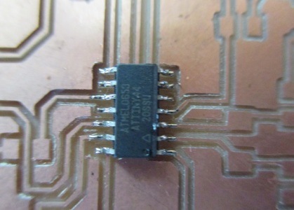
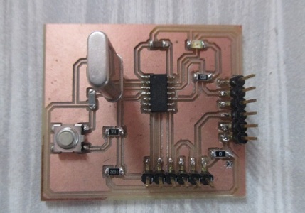
When I checked circuit ;there is mistake in routing as GND is not connected to Attiny 44;so I did this manually and board started working after programming.
Programming and working of board
Files:
Hello world.sch
Hello world.brd