Network and communication
Assignment:Design and build a wired &/or wireless network connecting at least two processors.
This weeks assignment mainly explores applications of electronic things in communication field. It improves our knowledge about communication devices and protocols. For this week we have to communicate two processors to each other through eithr wired or wireless connection. There are so many options for wireless communication like RF module , Zigbee Module, GSM ,Bluetooth,IR,GPS etc. I tried here first with RF module but code is tricky so went with wired connection.
What I did?
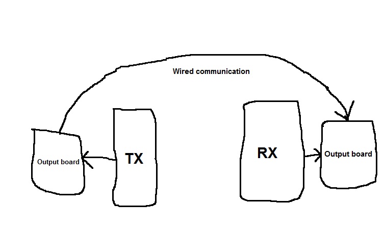
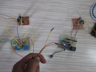
For communication I used wired connection between Transmitter and receiver boards.Im using these boards inside my final project.
Board design:
Transmitter :
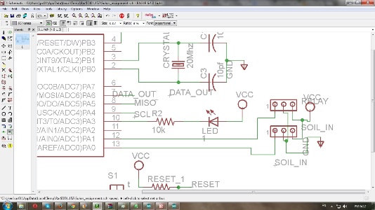
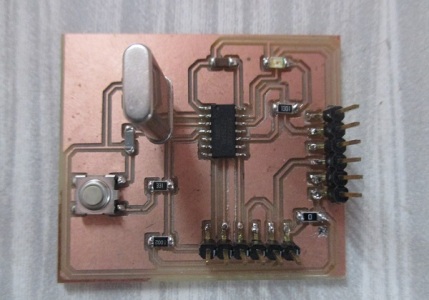
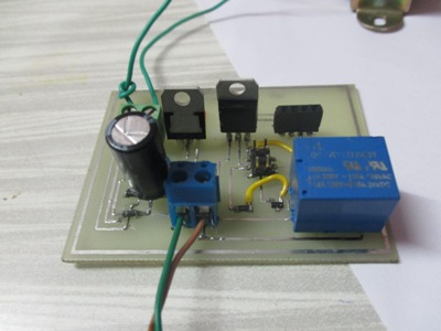
At transmitter end I used Helloworld board and output device board to transmit signal through wire. Made design and soldered both as per need.Inside helloworld board PA0 pin defined as input pin as well as PA1,PA3,PA6 pins are output pins. At input side connected soilmoisture sensor and at the output relay at PA1, LED at PA3 and data out at PA6 connected. Here I used data out pin (PA6) for transmission. Go through circuit diagram as follows :
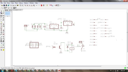
Below is hello world board circuit diagram ; Inside this PA6 pin defined as MOSI as well as DATA OUT pin .
 |
 |
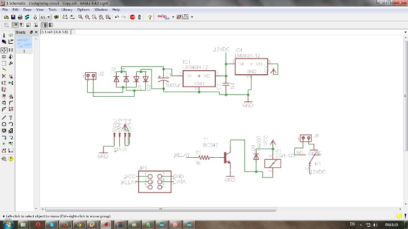
Above board is connected with Output board which having connector to connect communication devices. Connector pin is having VCC ,GND ,DATA ,ANT supply .
 |
 |
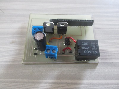
Receiver:
At receiver side again used hello world board but here PA0 pin is INPUT pin taking input from DATA IN pin placed on output board connector. Here output board is having different connector to connect different communication devices.
 |
 |
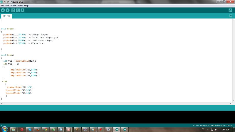
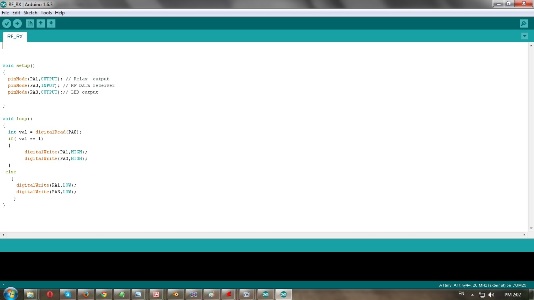
Programming:
Transmitter : To programm both boards I used Arduino IDE . At transmiiter end PA0 pin of Attiny 44 defined as a INPUT pin taking soil sensor input. PA3 and PA6 pins are defined as OUTPUT pins . LED is connected to PA3 pin and data out is connected through PA6. When Soil moisture input is HIGH then both output pins are HIGH.At the time data out pin sending a signal through wire.
Receiver: Here same boards are used but pin PA0 of attiny 44 is taking input from connector DATA IN pin which is connected with wire to transmitter end.At output end I connected Buzzer through relay and LED for indication .Both pins goes high when there is data signal to connector by transmitter.
Connections :
Connected following pins to each other by wire .
| Transmitter | Reciever |
| VCC-> | VCC |
| GND-> | GND |
| DATA-> | DATA |
Go through video link for operational video:
Wired communication
Download all files from here :
Hello world board
Output board
Source code