Output devices
Assignment: Add an output device to a microcontroller board you've designed and program it to do something.
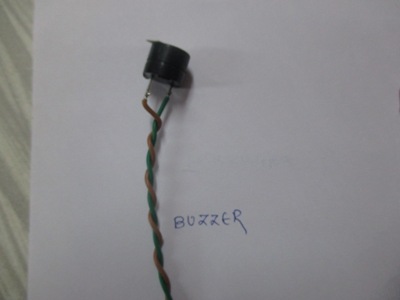
In last assignment I studied how to configure Input devices with microcontroller ,in thnat i used soil moisture sensor to measure content inside soil for my final project. Now here for same project Im going to add relay switch at the output side to control either solenoid switch or motor. Also I added one buzzer with another circuit board and connected it with wire. So now if we consider soil sensor at the input then when input is High relay will turn ON motor contradictory when soil input is low it will turn off motor.
Same like input device here I used Hello world board as a main unit. Inside this I used PIN PA0 is input pin and PA1 and PA6 are output pins.You can see more about Hello world board here.
Circuit Description :
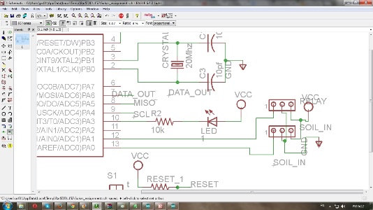
Here inside circuit diagram I used PORT A as a input as well as output port. At the input side I have connected soil moisture sensor and output side there is one relay to operate motor ON /OFF or 12 VDC solenoid valve. In hello world board schematic PIN A1 is output pin for relay and PA6 is data transmission pin through wired connection to another output board. Go with schematic as follows:
Output board:
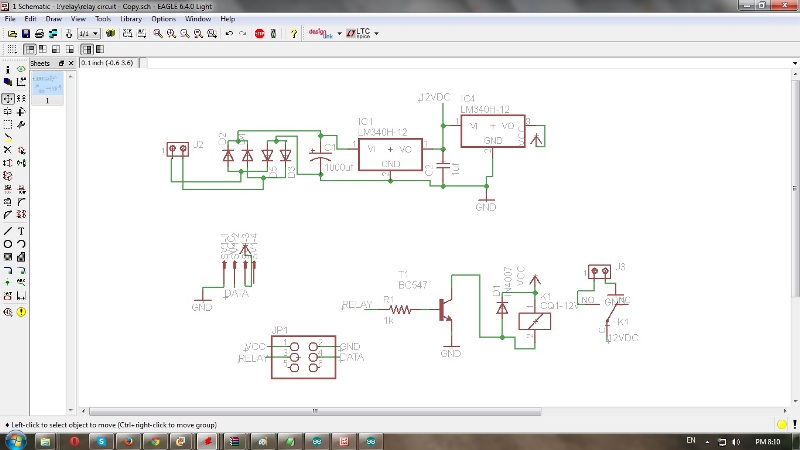
To take output from Hello world board designed another output board which contains mainly power supply and relay circuit with buzzer.
I also added one connector which having PA6 output pin connetion and we can use it to connect another output devices like RF module , Zigbee module ,IR transreceiver etc. Inside schematic pinheader contains VCC,GND supply for hello board and relay input signal and output data siagnal for connector. For final project I have to connect motor with relay .
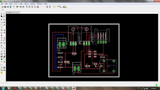
Board file:
Soldering : There is no bits available of 1/64 in our lab so printed this board from outside.Placed all components on this;some of these are through hole.
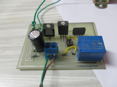
At the output side of relay I connected buzzer to see operation ; Insied final project I have connected Motor to irrigate vertical garden.
 |
 |
At the output side of relay I connected buzzer to see operation ; Insied final project I have connected Motor to irrigate vertical garden.
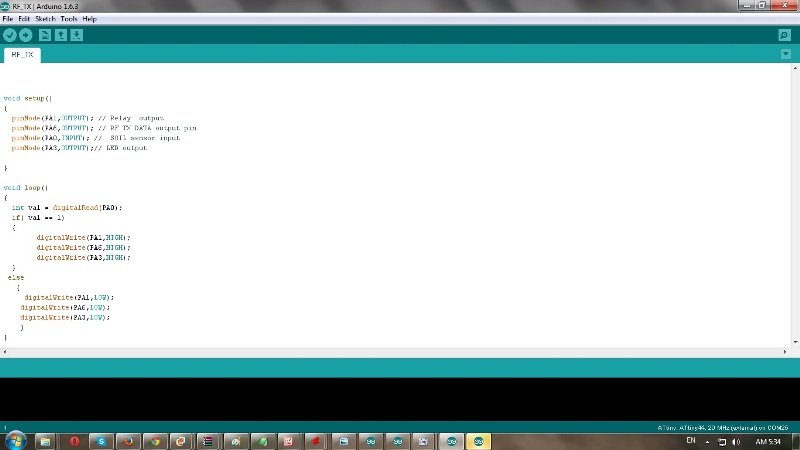
Programming: I did programming through arduino IDE. Defined PA1 and PA6 pins of ATTINY 44 as output pins. So when there is Input at pin PA0 then output pins goes high ;generally it remains low. Go through program here:
Now connected respective pins to output board i.e.VCC GND Relay output and Data output. At output side of relay connected buzzer. See connections below.
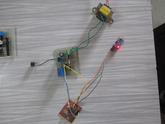
Here at input soil moisture is connected when we short both pins of sensor ;it gives low output at input So it will turn off buzzer at the output .Initially both relay and Sensor input is high state. Here at input soil moisture is connected when we short both pins of sensor ;it gives low output at input So it will turn off buzzer at the output. Initially both relay and Sensor input is at high state.
Go through following operational video link.
Output device video link
Opearation in final project
Files : Download files from here. Hello world board
Output device board
Soil Moisture source code.