System Integration
System integration consists of connecting and making all the subsystems that make up a project work in a coordinated way: the electronics, mechanics, firmware, physical structure, and user interface. In my project, this means making the cut crystal assembly machine — with its motors, drivers, PCB, conveyor belt, counting camera, and MQTT dashboard — function as a single coherent machine capable of automating the crystal assembly process for Lámparas y Candiles de Oaxaca.
Made a plan for system integration for your final project?
Plan for System Integration
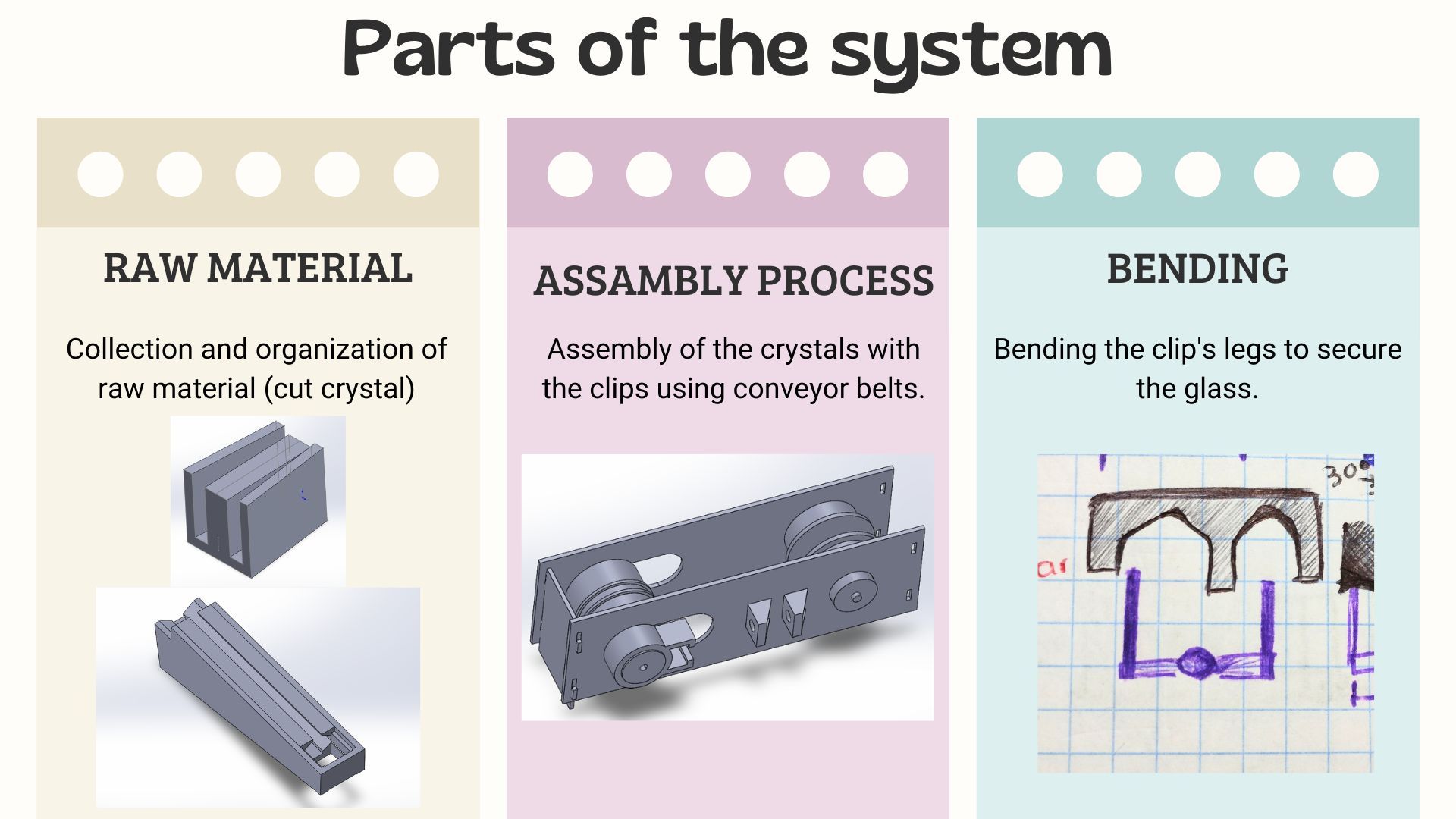
From my final project page, I defined the stages of the production process that the machine must automate and divided them into three main blocks: Raw Material (collection and organization of raw material), Assembly Process (assembly of crystals with staples using conveyor belts), and Bending (bending the staple legs to secure the crystal). For week 15, this planning translates into identifying which electronic, mechanical, and software subsystems need to be integrated and in what order.
System integration diagram showing how all subsystems connect.
The integration includes:
- For the staple dispenser, the original plan was to build the system documented in Week 03 — Laser & Vinyl Cutting, which showed a rail system with progressively narrowing walls to orient the staples. However, due to time constraints and mechanical complexity, it was replaced with a manual system that is easy to use for parameterizing the staple angle.
- The PCB model for stepper motor control (Week 12 — Mechanical Design, Machine Design) controls 4 NEMA 17 motors with DRV8825 drivers from a Raspberry Pi Pico 2W.
- The MQTT communication diagram from Week 14 — Interface and Application Programming illustrates how the dashboard, the HiveMQ broker, and the XIAO ESP32-S3 exchange configuration, control, and status messages. The same system will be used to move the motors step by step, but using the Pi Pico 2W.
Documented your plan with CAD and/or sketches for system integration?
3D Models of the Components
To plan the physical integration of the machine, 3D models of the main mechanical components were developed: the crystal organizer, the staple organizer, and the general assembly.
Mechanical Components
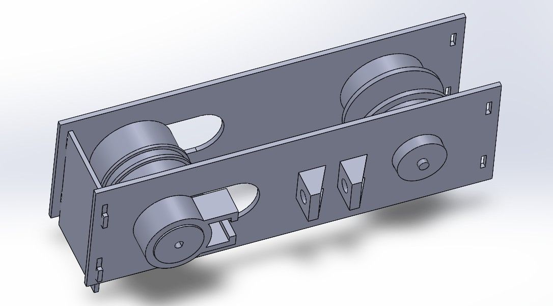
1. General Assembly View
Overview of the machine assembly showing how the main mechanical components fit together within the structure.
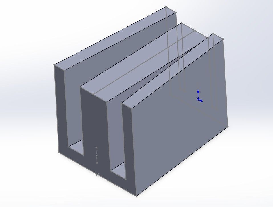
2. Crystal Organizer
Component designed to receive and orient the cut crystals so they are correctly positioned before the assembly step.
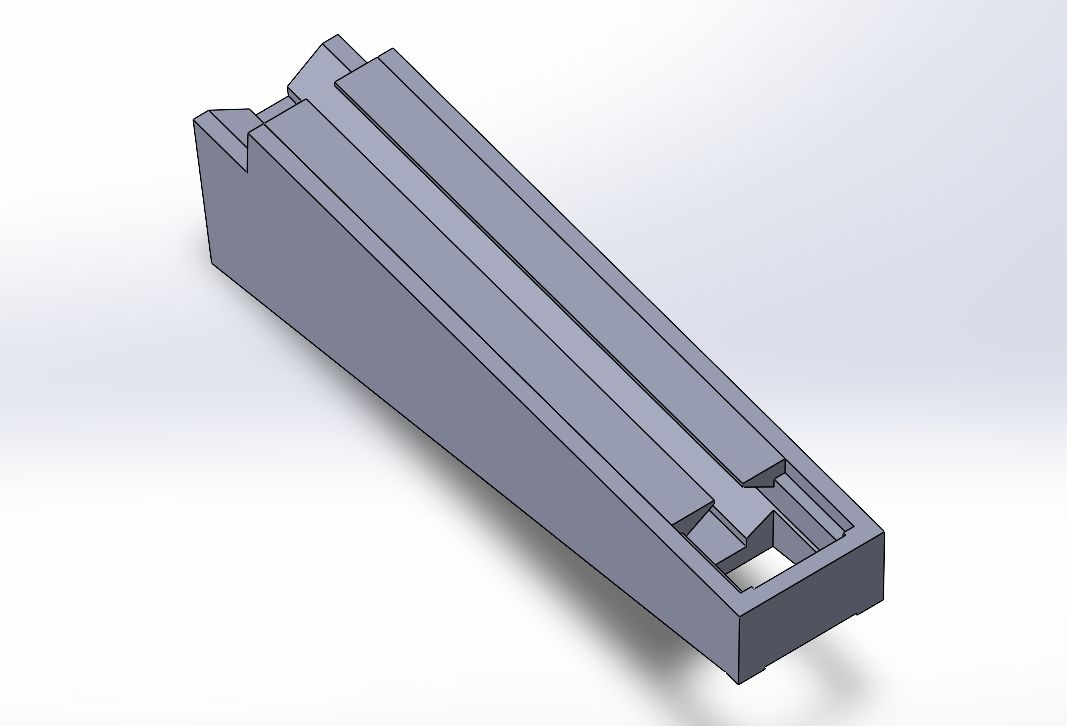
3. Staple Organizer
Component designed to receive and orient the aluminum staples at the correct angle before they are assembled onto the crystals.
System Workflow Diagram
Although there is no complete CAD assembly of the full machine yet, a workflow diagram was developed to represent how the system works end to end: from raw material input to the finished assembled crystal strip, passing through each subsystem involved.
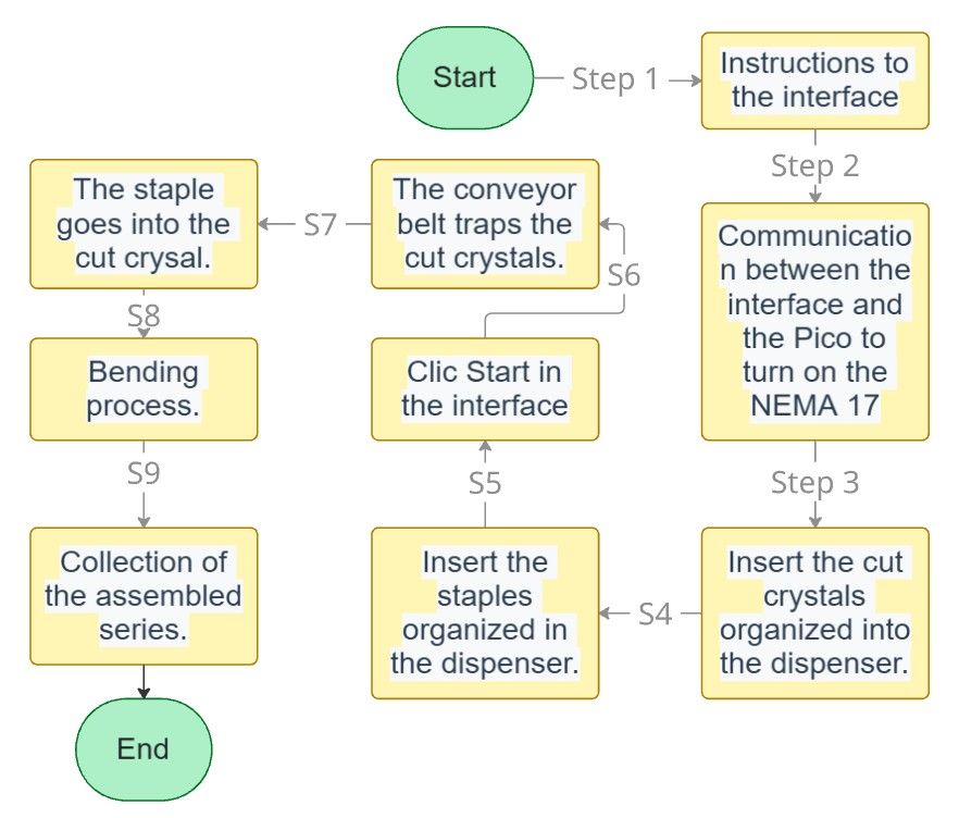
Workflow diagram representing the system from end to end.
Documented system integration of your final project?
Documentation of System Integration
The documentation of the system integration is distributed across multiple weeks of Fab Academy, each covering a specific subsystem. The complete breakdown can be found in the Summary section of this page, where each week is linked to its specific contribution to the final project.
Linked to your system integration documentation from your final project page?
Link from Final Project Page
This Week 15 page is linked from the Final Project page, alongside the weeks corresponding to each subsystem (Week 03, Week 09, Week 10, Week 12, and Week 14), so that the evaluator can navigate from the final project page to each specific piece of documentation.
System Integration
The system integration was achieved through a container box with 3D-printed lids, which housed the following components:
- 12V 5A power supply
- Electronic boards
- Stepper motor cable
System integration — outside view
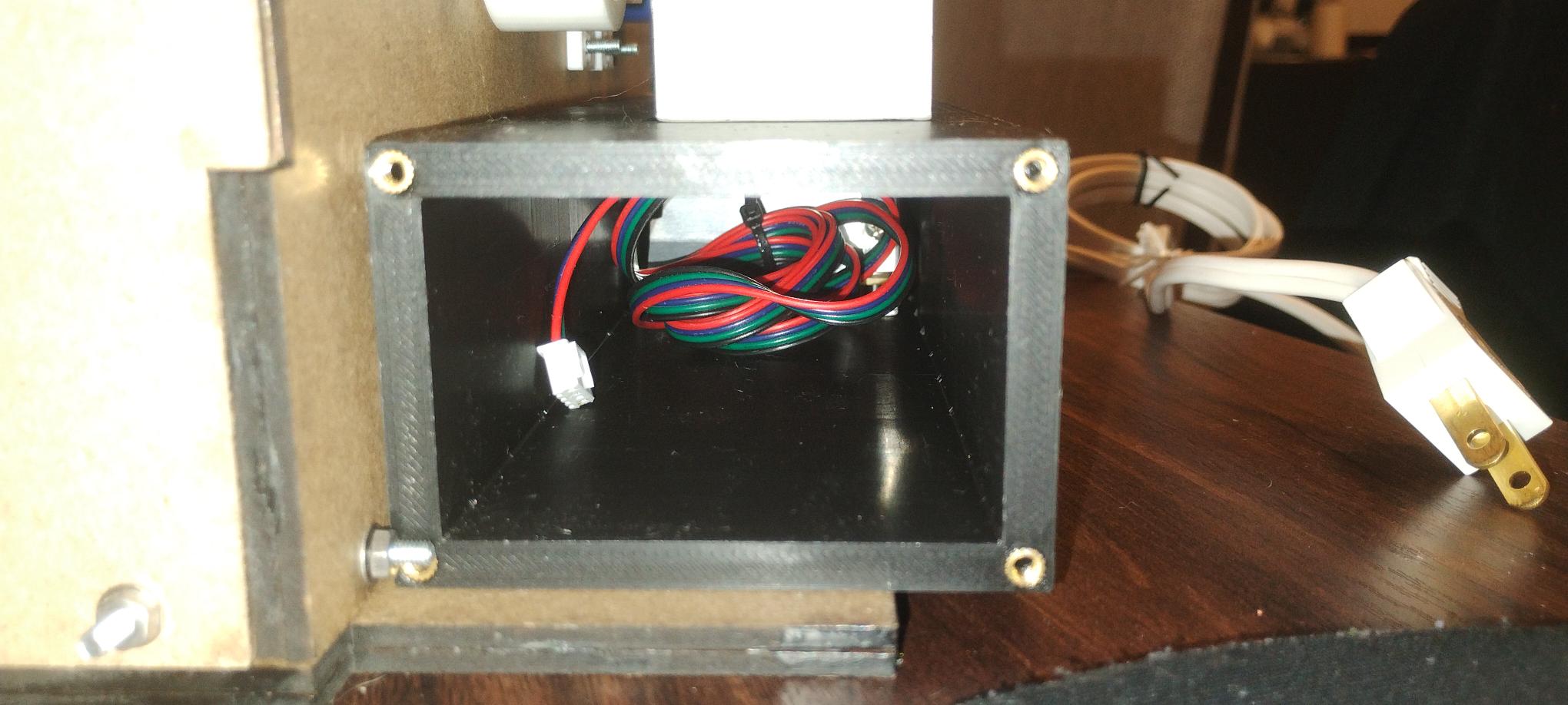
System integration — inside view
Packaging
Implemented methods of packaging?
Packaging Method
The machine's packaging will be a 3mm MDF box. The software used for this process is:
| # | Software | Use |
|---|---|---|
| 1 | SolidWorks | Box design. |
| 2 | Inkscape | Vectorization of the company logo. |
| 3 | Smart Carve 4.3 | Laser cutting software. |
At the moment I do not have the plans or the cuts already made; however, the idea would look something like this:
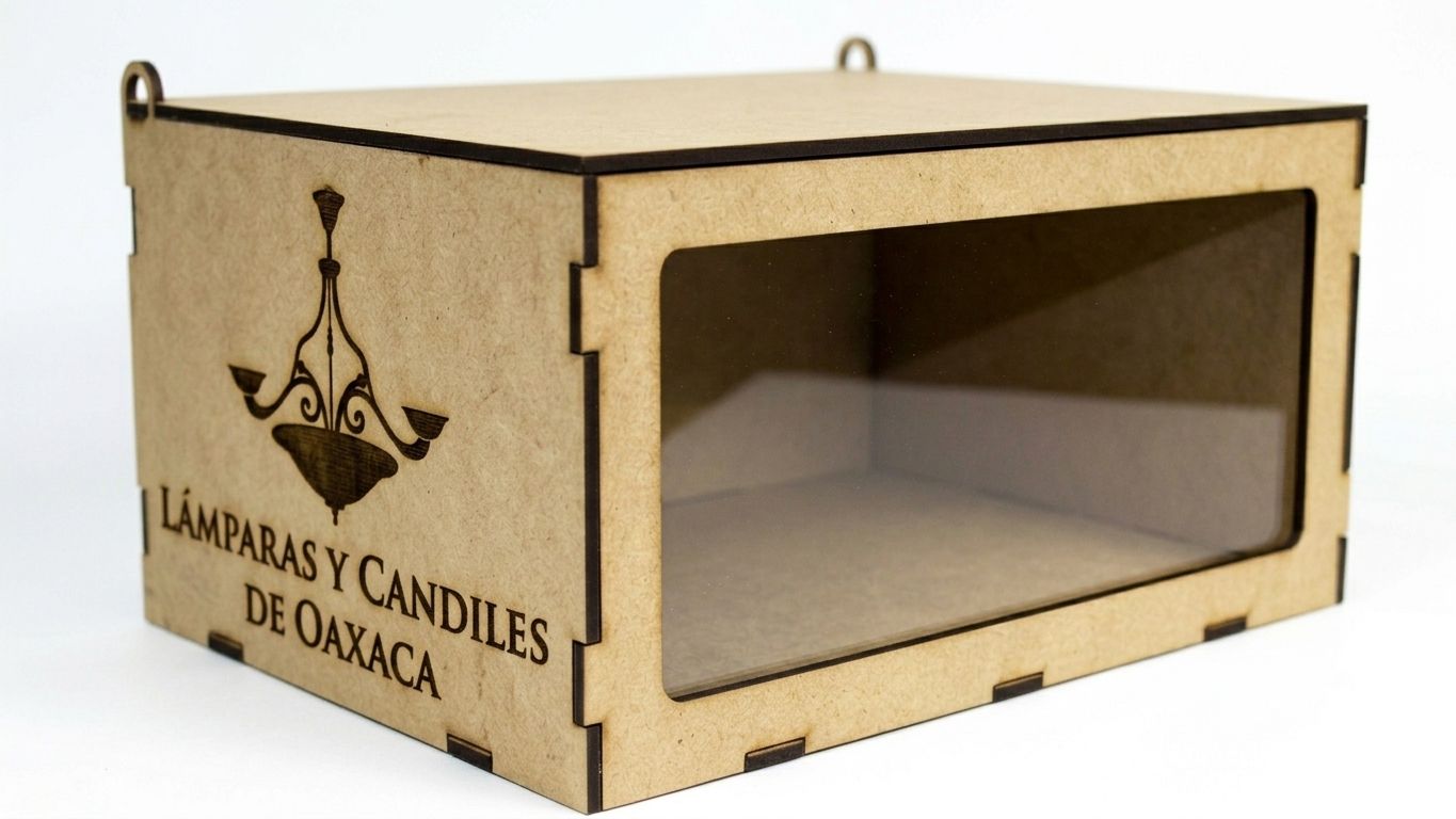
Note: The image above is for reference only and was generated with the Gemini AI using the following prompt:
Prompt: "A high-resolution, photorealistic studio photograph of a closed, rectangular laser-cut MDF (Medium-Density Fiberboard) display box, set against a clean, seamless white background. The box must feature precise, dark-edged finger-joint (box joint) construction visible on all corners. The front face of the box contains a large, rectangular acrylic viewing window, clearly showing an empty, wood-toned interior. On the left lateral panel, there is a detailed, precise dark laser engraving of an ornate, three-arm traditional chandelier. Below the engraving, also laser-etched, is the text "LÁMPARAS Y CANDILES DE OAXACA" over two lines. In the bottom right corner of the front frame, positioned below the acrylic window, is a distinct, intricate interlocking metal-effect 'AW' monogram logo, referencing the design from image_7.png. The lid features two small, functional metal loop hinges on the back edge, visible from this perspective. The lighting is soft and even, highlighting the fiberboard texture and the precision of the laser cutting and engraving. The perspective is a 3/4 front view looking slightly down."
Inside this box, the four NEMA 17 motors, their DRV8825 drivers, the 12V 5A power supply, the XIAO ESP32, and the crystal counting camera system will be housed, maintaining access for maintenance and for all the system's components, leaving an opening for the output of the already-assembled cut crystal strips.
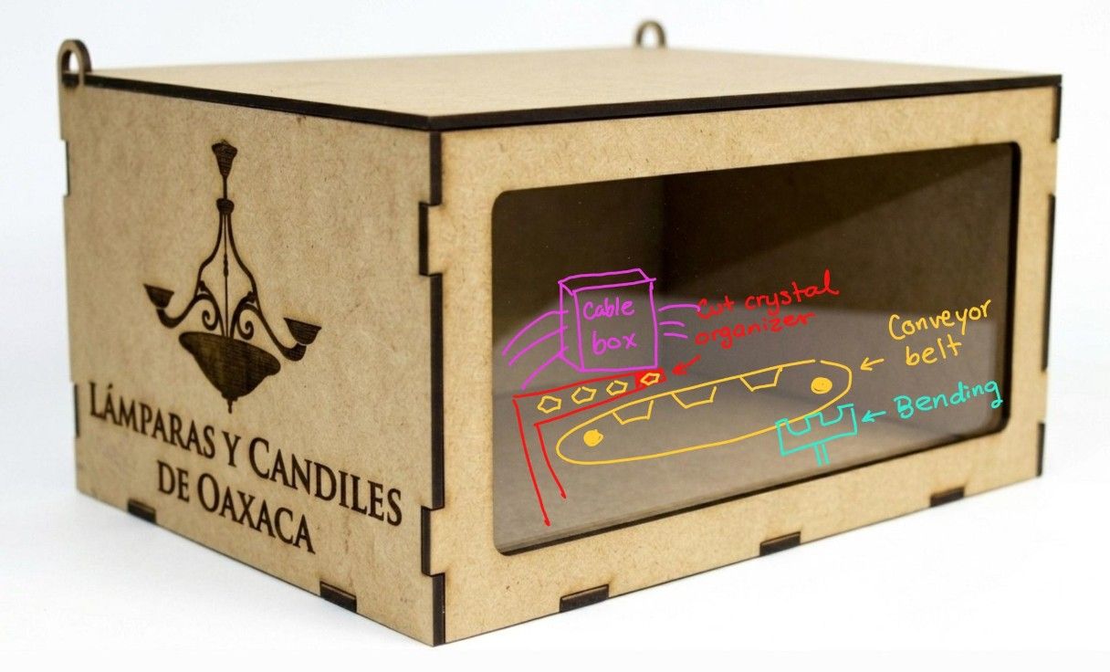
Diagram showing how cables and mechanisms will be organized inside the box.
Designed your final project to look like a finished product?
Designed to Look Like a Finished Product
The goal of the project is for the machine to be a functional and deliverable product for Lámparas y Candiles de Oaxaca. The following considerations were built into the design from the start:
- The box must have an industrial and clean appearance.
- The box must be closed, because due to the company's location there is a lot of dust, which could damage the components if the machine is not isolated.
- Digitally manufactured components (3D printing, laser cutting, copper PCB) to achieve professional finishes.
- An MQTT dashboard (documented in Week 14) that serves as the machine's operating interface: the operator configures the number of crystals required and the number of series desired, and monitors progress in real time from any device with a browser. Furthermore, this interface was designed especially with my family in mind, adapted to their needs to make it as comfortable and easy to use as possible.
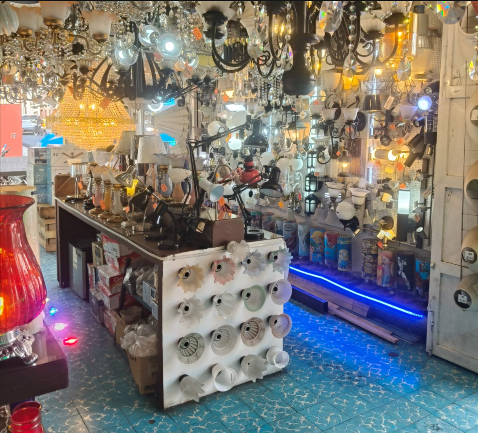
Lámparas y Candiles de Oaxaca — the store for which the machine is being built.
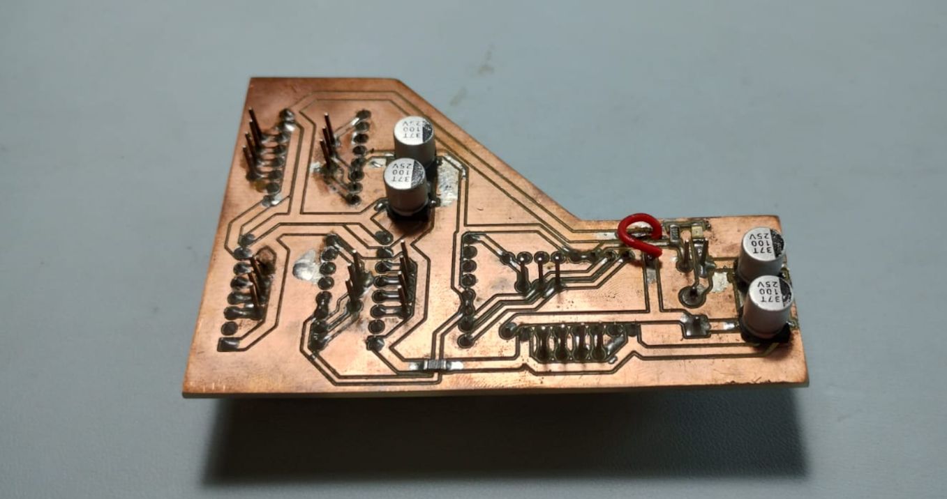
PCB designed to control the NEMA 17 stepper motors.
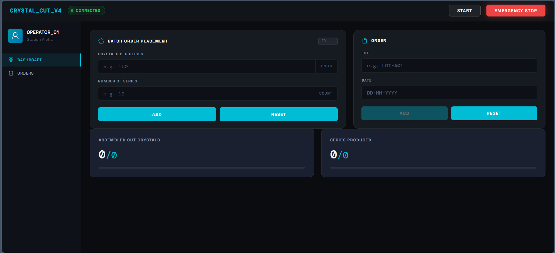
MQTT dashboard for configuring and monitoring the assembly line.
Packaging
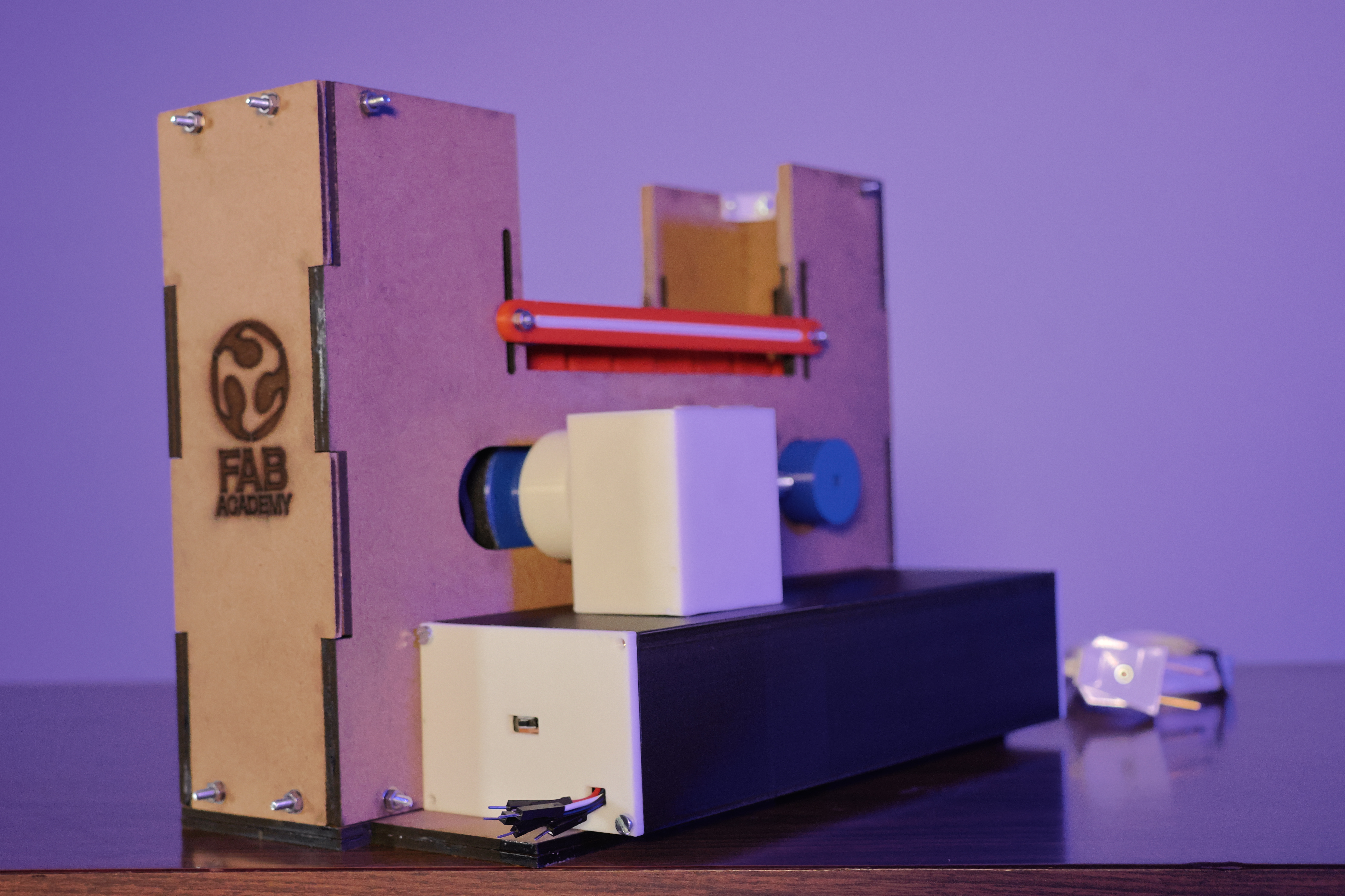
In the end, the same MDF machine structure served as the packaging. To give it a more polished presence, the logos of both Lámparas y Candiles de Oaxaca and Fab Academy were engraved onto it.
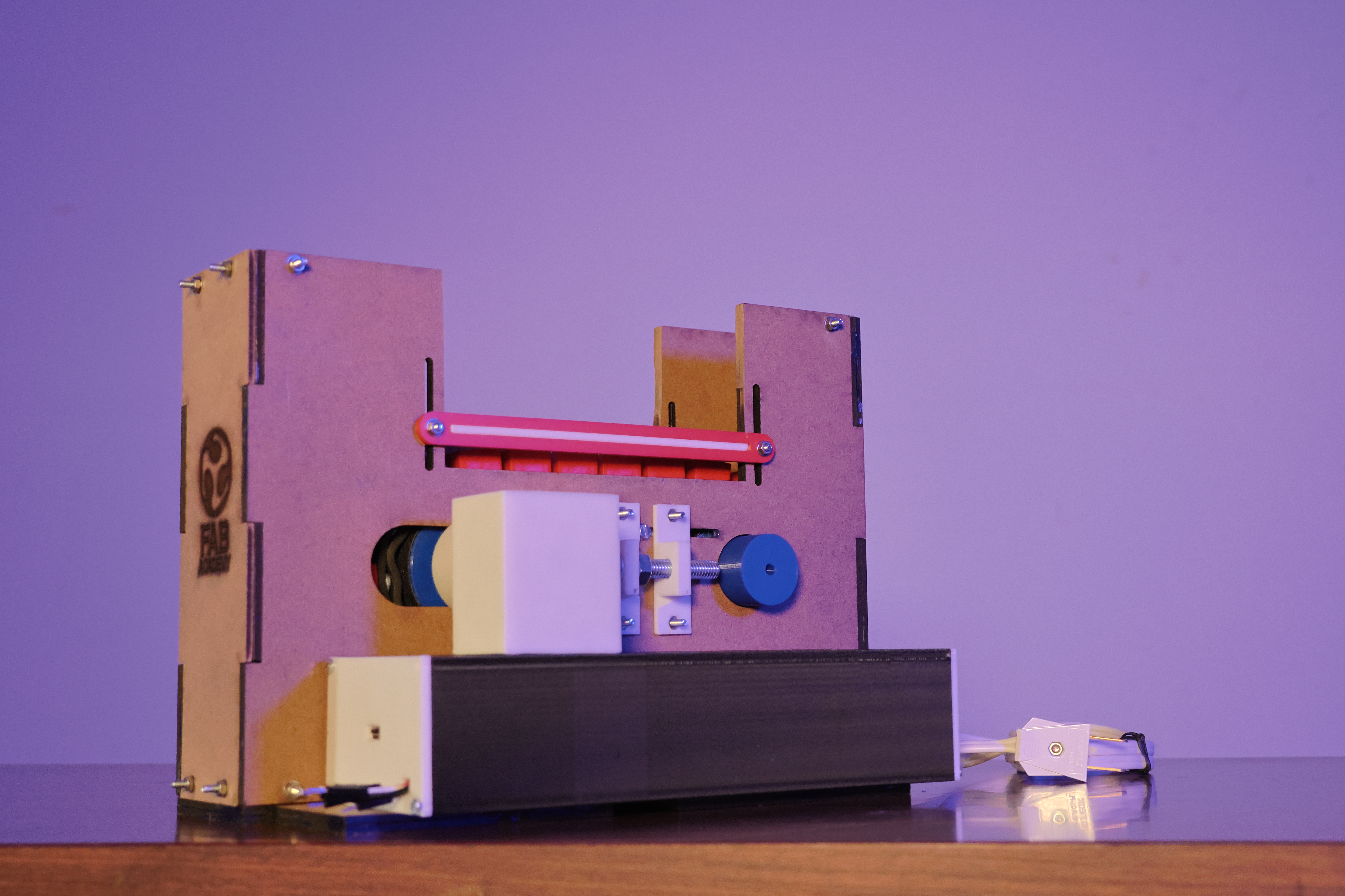
Machine structure
System Integration Summary
The documentation for the system integration of my project is distributed across several weeks of Fab Academy. The following table links each week to its specific contribution to the final project:
| Week | Contribution to the Final Project |
|---|---|
| Week 03 | Staple dispenser: laser-cut base container. Original idea, staple-by-staple dispenser system. |
| Week 12 |
Electronic design: schematic and PCB in KiCad. The other part of the board (with the Raspberry Pi Pico) is documented on the page of Joseph Alavez Jaimes — Week 12, with whom I teamed up during the PCB week and who helped me build the other part of the modular board. |
| Week 09 | Input Devices: circuit with a camera for counting assembled crystals. |
| Week 10 | Output Devices: PCB for controlling two NEMA 17 motors with DRV8825 drivers (explanation of how these stepper motors and drivers are used). |
| Week 14 | Interface: MQTT dashboard for configuring and monitoring the assembly line. |
| Week 15 | System Integration: integration of all the subsystems above. |