Laser Cutting
Group Assignment
Safety Training
- Never look directly at the laser beam.
- Do not insert your hands while the machine is operating.
- Do not cut with the door open.
- Avoid unknown plastics (toxic fumes).
- Stay alert for fire hazards due to incorrect parameters.
- Turn off the laser button before moving the head manually.
Software Used
- Smart Carve 4.3: Primary laser cutter software.
- Lightburn: Advanced alternative for design and cutting.
Setting Parameters in Smart Carve 4.3
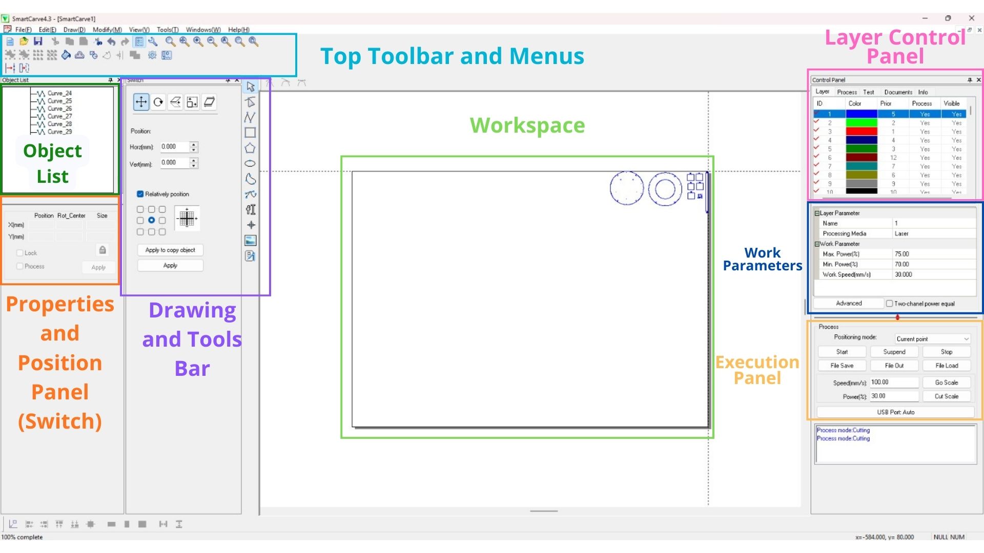
The program interface is divided into the following key sections:
- Top Toolbar and Menus: Quick access to files, editing, and zoom tools.
- Drawing and Tool Bar (Left Side): Object selection, geometric drawing, and node editing.
- Object List: Shows all elements present in the design (e.g., Curve_24, Curve_25).
- Workspace: Where the design is visualized over the machine's bed.
- Work Parameters: Adjustment of speed and power for each color layer.
- Execution Panel: Command center to Start, Stop, and "Go Scale" (Frame).
What I learned this week:
- I learned to calculate the laser cutter's kerf (0.138 mm) and understood how to apply tolerances correctly: increasing by kerf/2 for male parts and decreasing by kerf/2 for female parts.
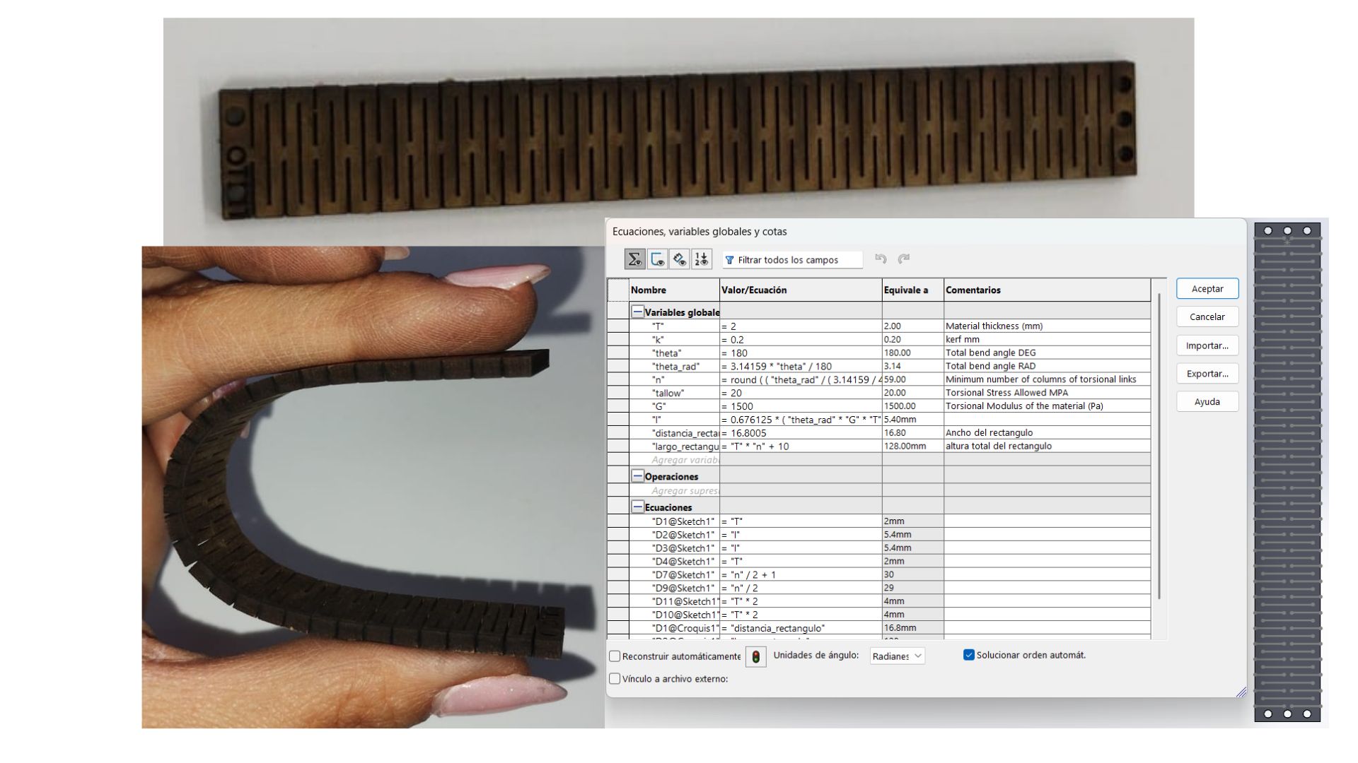
- I learned how to parameterize designs in SolidWorks using an equation table with global variables, allowing the entire design to adjust automatically when the material thickness changes.
- I experimented with living hinges and discovered that the only parameter that worked to simulate a conveyor belt was "Test 1" (maximum flexibility), and that cuts must not converge with the edge of the piece.
What I learned from the group page:
- I learned that the Fab Lab's CO2 laser operates with three key parameters: maximum power (for straight sections), minimum power (for curves and corners to avoid "node burning"), and speed; there should always be a 10–20% difference between both power settings.
- I understood the different types of joints possible with laser cutting: Snap Fit, Finger Joints, Wedge, Pinned, Press Fit, and Flexure Joints, and when it is most appropriate to use each one.
- I learned the complete process to operate the laser machine safely: from turning on the equipment with the safety key to calibrating the 5 mm focal distance and saving the file in .oud format to load it via USB.
Kerf
What is it?
Kerf is the width of the groove or the material lost during the cutting process. Various test files were created to measure these lost millimeters accurately.
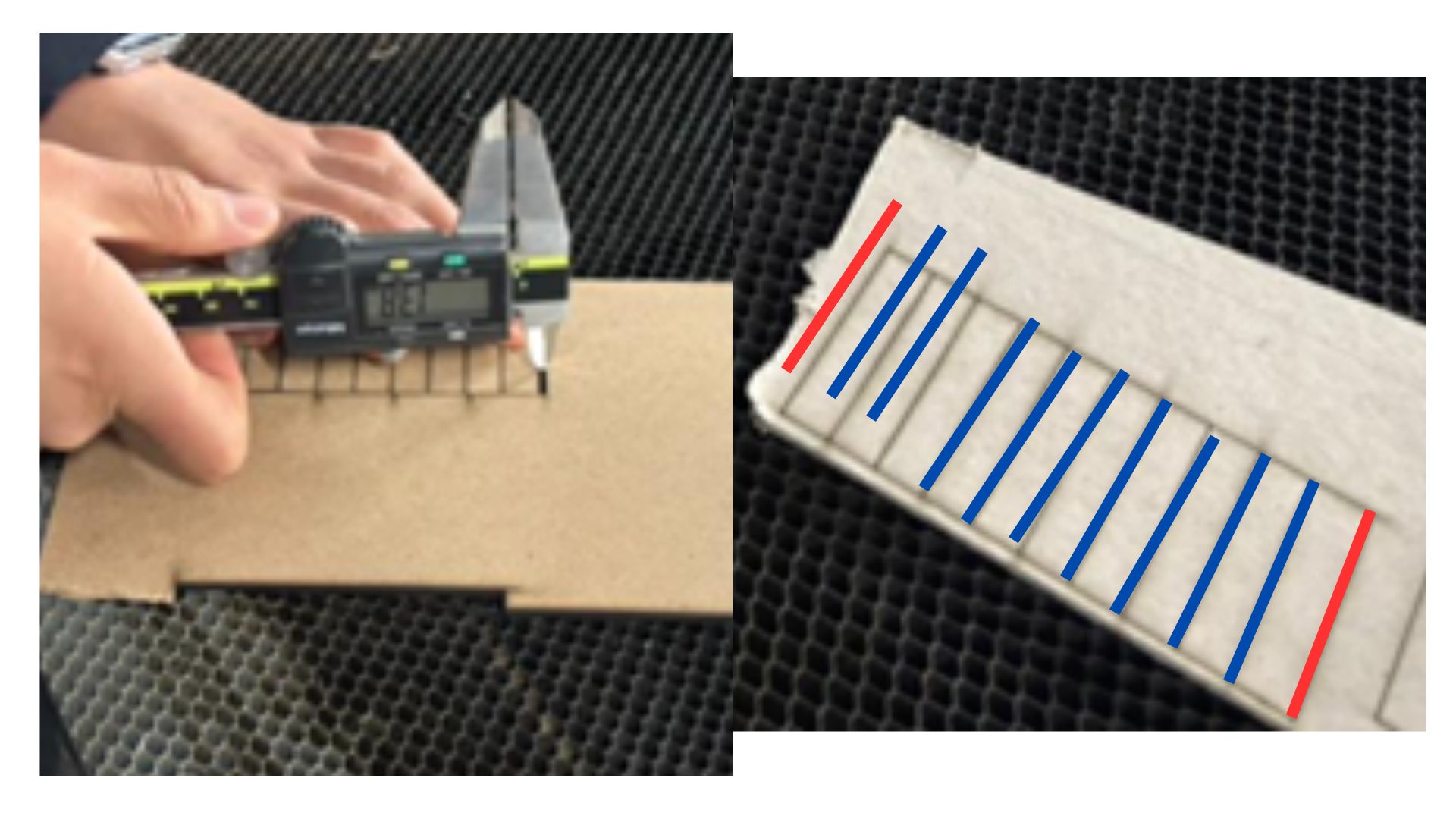
How is it calculated?
- A rectangle with internal lines is designed in the software.
- The design is sent to the laser cutter.
- The resulting distance is measured using a vernier caliper. In this test, there were 9 internal lines (marked in blue) and 0.5 for each external line (marked in red), totaling 10 lines. The total measured value is divided by this number (1.38 / 10 = 0.138 mm, which is the Kerf).
Formula: Total space (1.38 mm) / Number of lines (10) = 0.138 mm
Design Conclusions
Personally, I found it challenging to understand how tolerances work during the design phase. After many trials, I reached the following conclusions:
- Male Piece (external parts): Increase the size by Kerf / 2.
- Female Piece (internal parts): Decrease the size by Kerf / 2.
Joints and Kerf Variations
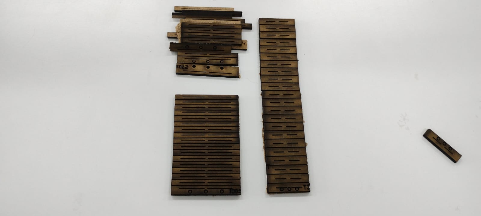
I utilized various joint designs from a folder shared by my instructor. Although some tests were not part of my final design, I performed several trials with Kerf tolerances.
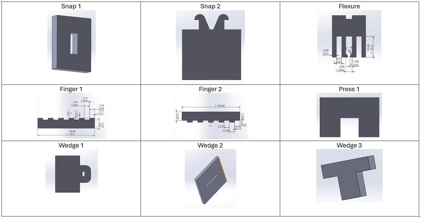
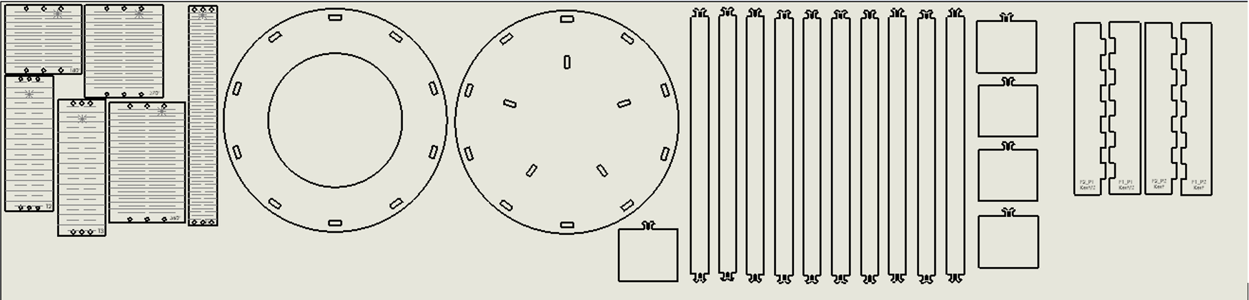
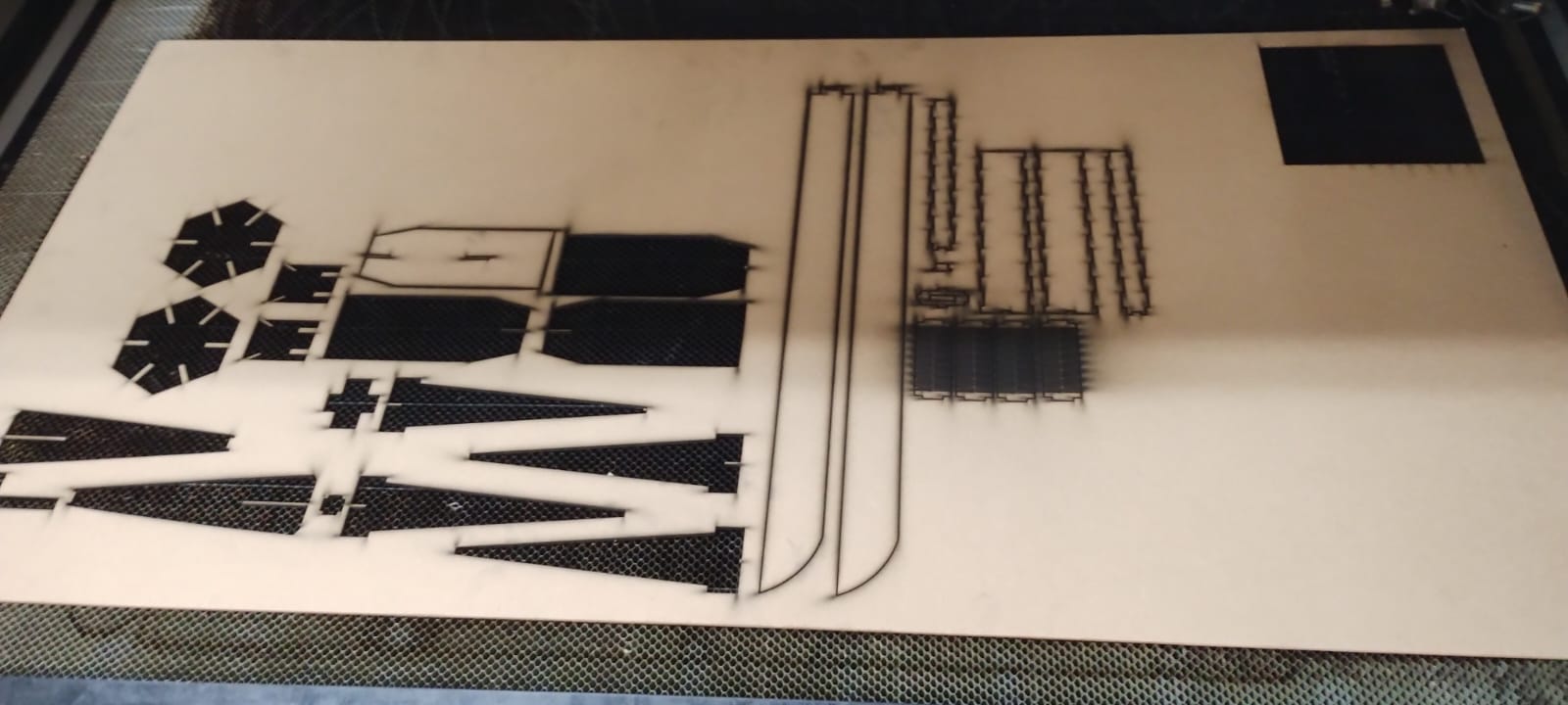
As such, this was no longer part of my design; however, I performed the following tests with kerf tolerances. The following image shows each of the pieces that were cut along with their parameters.
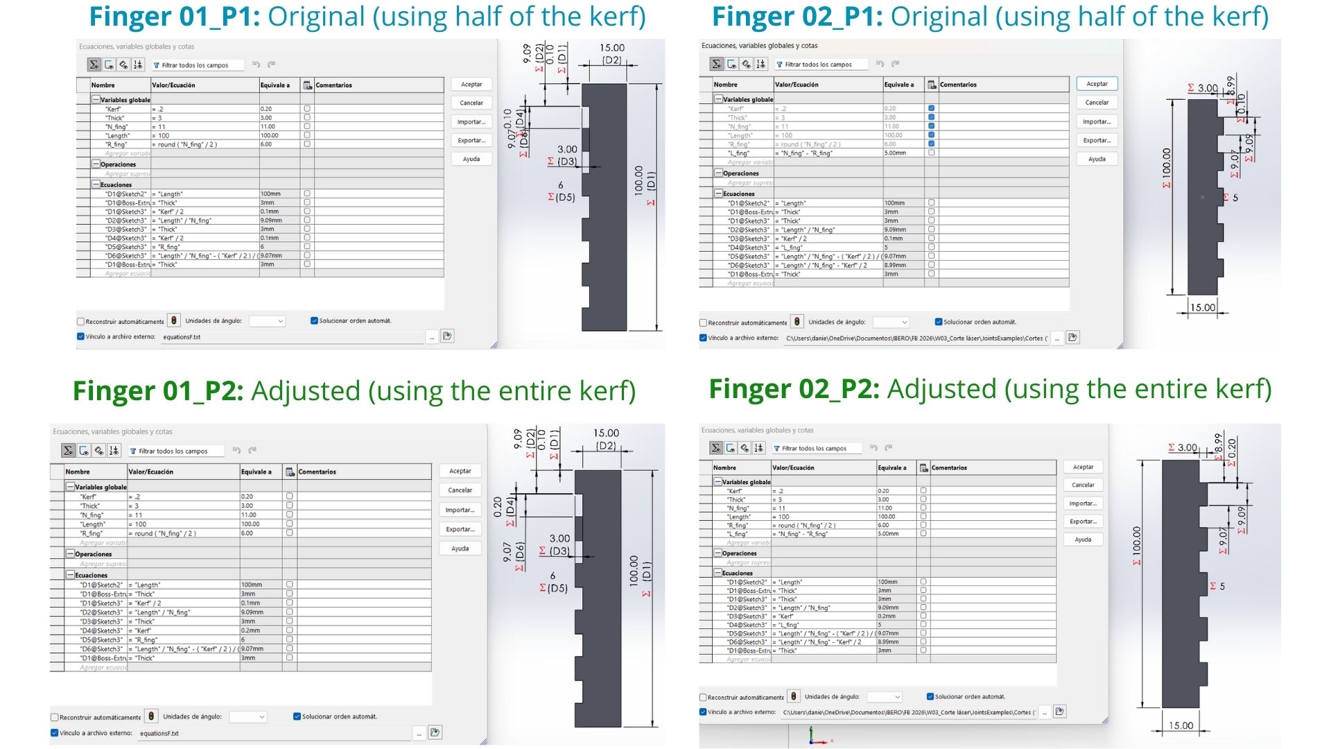
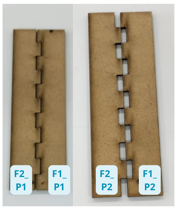
After testing, the best-fitting joints were "Finger 2_P1" and "Finger 1_P1"; in both cases, the fit was achieved by subtracting half of the Kerf.
Tolerances for Assembly
| Fit Type | Calculation | Observation |
|---|---|---|
| Loose Fit | Design + 0.0695mm (1/2 Kerf) | Slides in smoothly but falls out when flipped. |
| Perfect Fit (Press) | Design + 0.08 to 0.1mm | Ideal adjustment for assemblies. |
| Very Tight | Design + 0.139mm (Full Kerf) | Enters very forced; may break the material. |
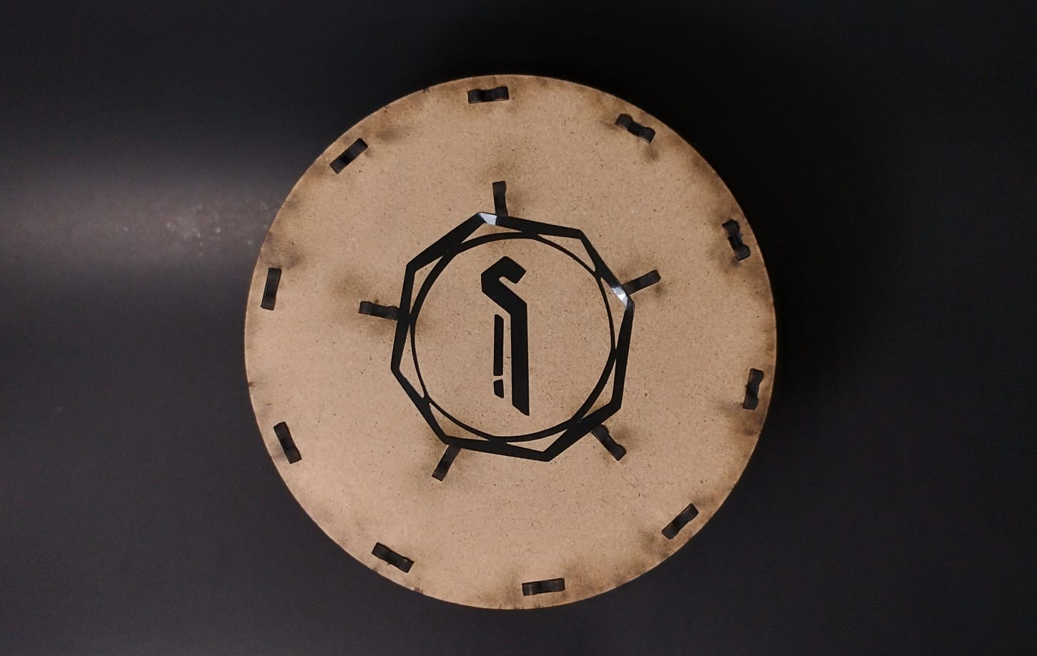
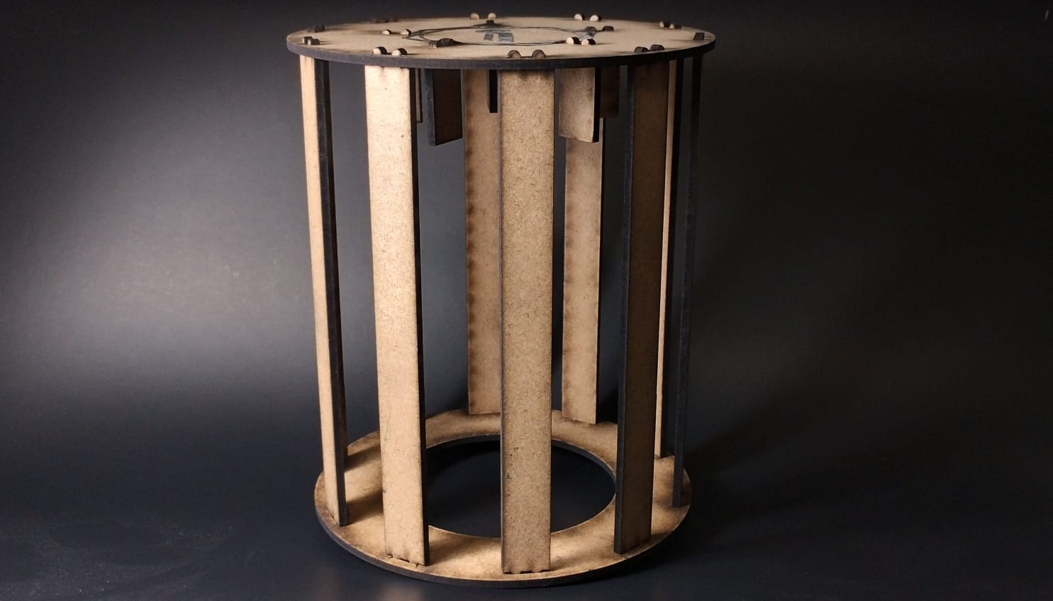
Design & Parametric Joints
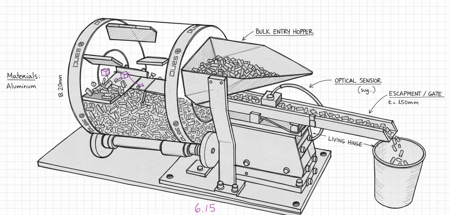
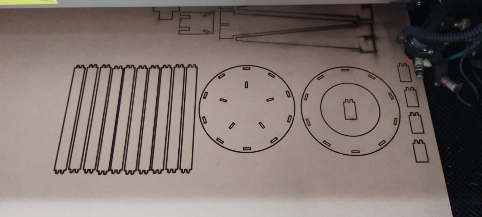
Inspiration: Drum Feeder
My design was based on a drum machine used for organizing staples. I used AI (Gemini) to clean the sketch and structure the assembly steps.
I gave Gemini the following prompt to clean up my sketch:
“Hola! quiero que me ayudes a hacer un boceto en limpio de una máquina que funcionará como una organizadora de unas piezas que parecen unas grapas. Te adjunto el boceto que yo hice (del cual necesito que hagas en limpio el diseño y que le pongas los nombres traducidos al inglés de cada parte que señala mi boceto) para que lo pases en limpio. Además, te adjunto el link de youtube de la máquina de la que sacamos la inspiración del funcionamiento y algunas piezas: Drum Feeder with Piezo Vibratory Linear and Loading Chute”
Parametrization on SolidWorks
Parametrization Process
1. Global Variables
In SolidWorks, I used the Equations table to define "kerf", "material_thickness", and "total_width". This allows the material to be changed while the entire design adjusts automatically.
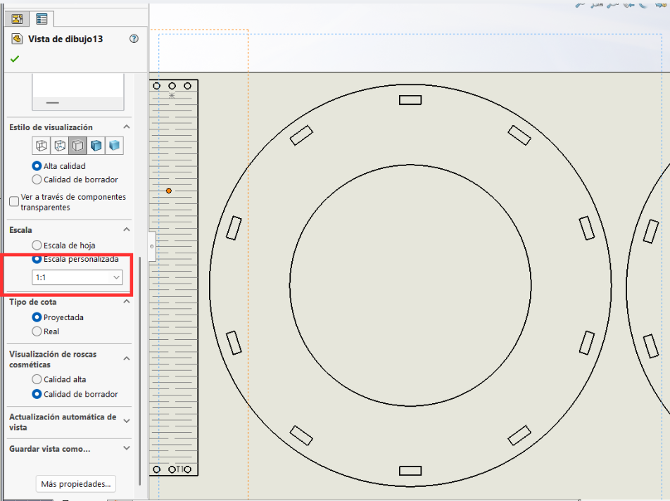
2. Extra note
You must be careful because when parts are inserted, they often appear in the workspace at a scale other than 1:1. Therefore, you must ensure that "Custom Scale" is correctly set in the side panel.
3. Extra note 02
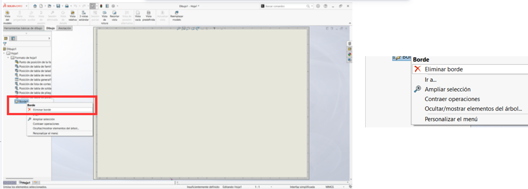
Note: To delete the borders, follow these steps:
- Double-click on "Sheet Format".
- Right-click on "Border 1".
- Select the "Delete Border" option.
- Select the text box at the bottom and press "Delete".
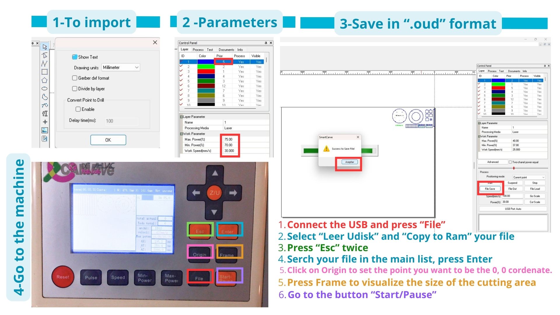
4. Laser Cutting
The steps for laser cutting in the machine are the one shown in the image.
Cutting on the Machine
The first time I attempted to cut with the machine, I made the mistake of using laser number 2 instead of laser number 1, which is the one typically used for cutting. As a result, the piece was only scorched but not cut through. I know it wasn't due to my parameters, as they were the same ones I used later to successfully cut using laser number 1.
Another interesting situation occurred when I sent some pieces to be cut for another project I am working on. I sent everything in the same DXF document using the same parameters (Max Power: 75, Min Power: 70, Speed: 30), yet it only cut through the first half of the pieces. For future occasions, I recommend using slightly more power, as the bed leveling may not be perfectly uniform across all areas due to wear and tear.
Extra Tools
From the instructor's page (Group Assignment: Computer-Controlled Cutting | Ibero Puebla), these are the resources used for the project:
| Resource | Description / Link | Format |
|---|---|---|
| Downloadable Document | Joints Examples - Kerf variation and tests | ZIP File |
| Reference Book | Snap-Fit Book - Types of joints and mechanics | PDF Document |
| Design Tool | Lattice Hinge Design — Choosing Torsional Stress | Web Link |
| Living Hinge Template | Parameterized hinge provided by the instructor | SolidWorks (.SLDPRT) |
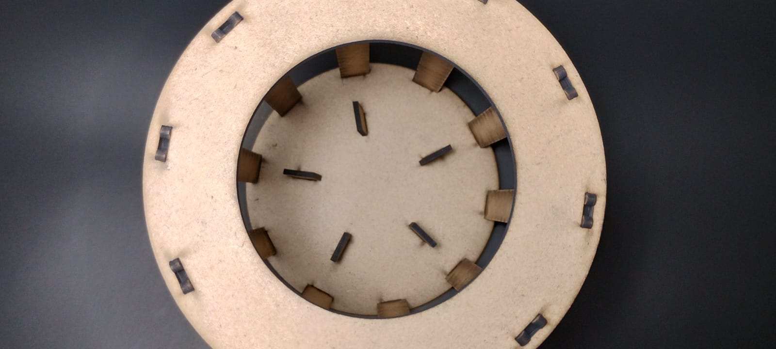
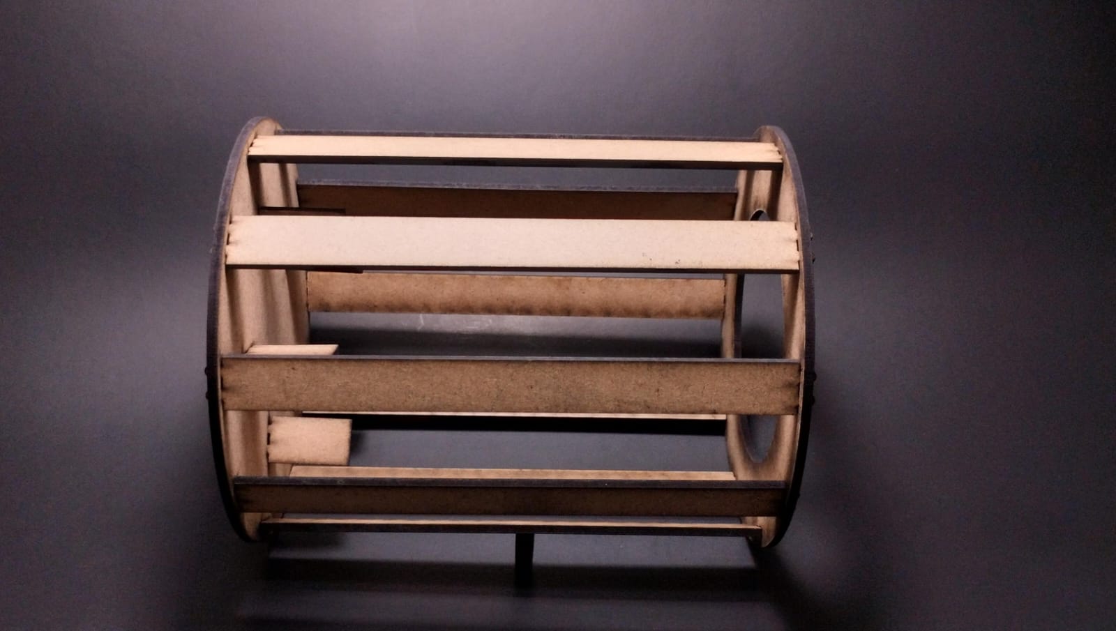
Results
Vinyl Cutting
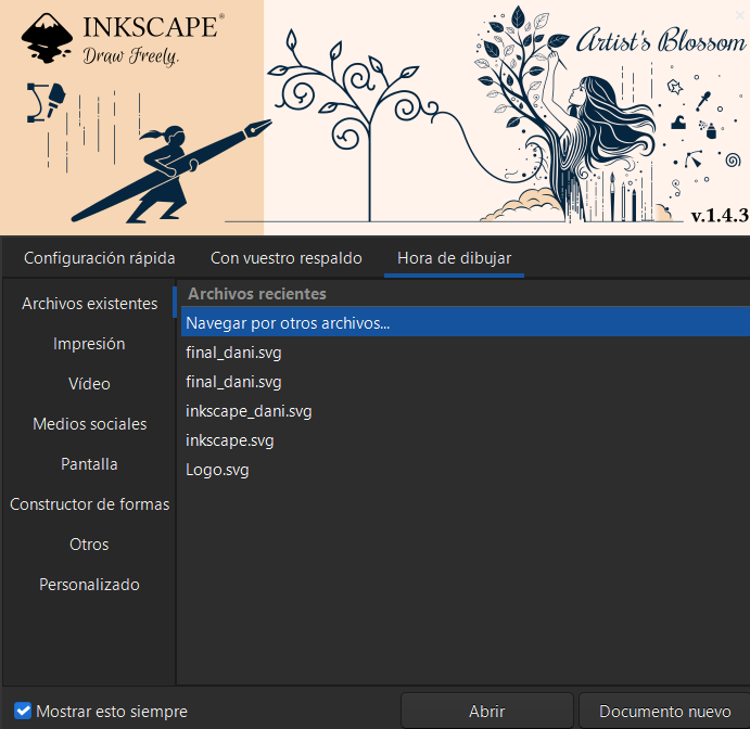
1. Software and File
A driver for Inkscape was used. We opened the file in .smv format (Inkscape header format).
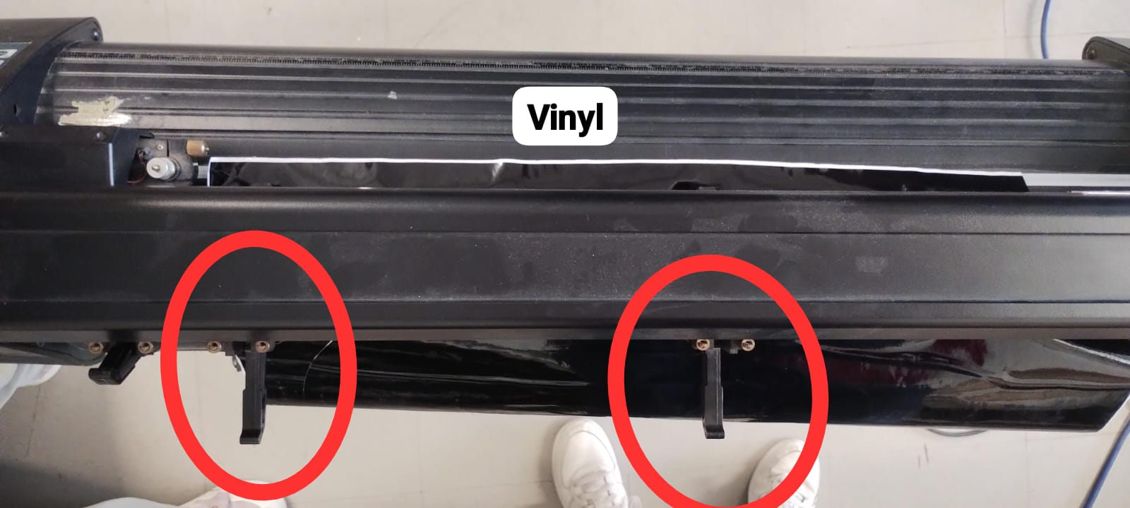
2. Machine Preparation
Connect the machine, place the vinyl, and adjust the pinch rollers to secure the material.
3. Origin and Setup
Use the arrows to adjust the cutter nozzle to your desired origin point. In the software, documents are placed in "mirror" layout (just for arrangement, do not flip the image itself).
.png)
4. Final Parameters
Measure the actual length and width of the vinyl to set the workspace parameters before sending to cut.
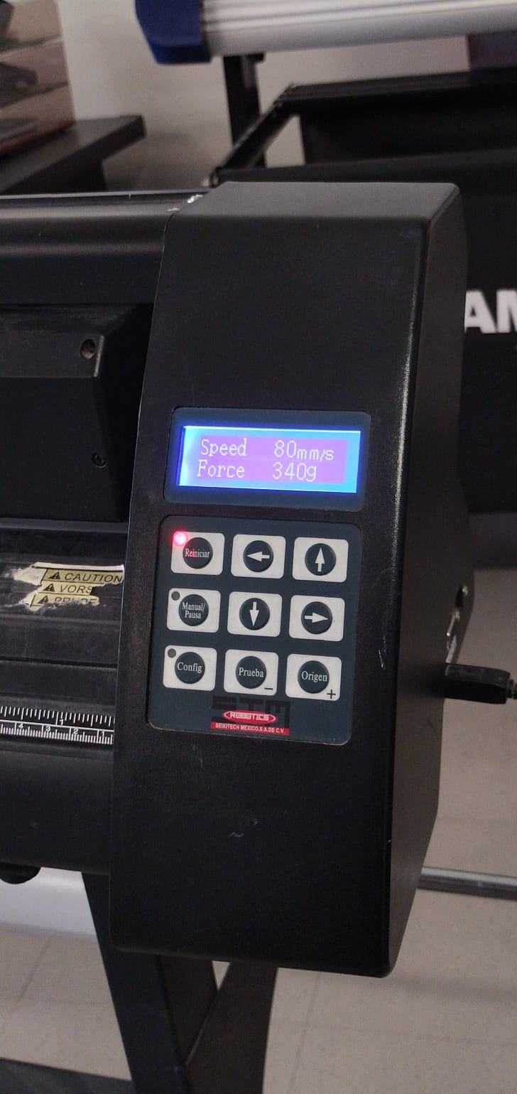
Parameters I used for the vinyl cut.
Final design of the vinyl cut on the material.
Living Hinges
What is it?
A living hinge is a thin, flexible type of hinge made from the same material as the rigid parts it connects. Instead of using pins or external mechanical components, it leverages the material's own flexibility to allow movement.
To use a living hinge in my project, I wanted to test different parameters to create a conveyor belt. To achieve this, I provided the Gemini AI with an image of a parameterized hinge document given by our instructor, along with the following prompt to determine which parameters to modify for my tests.
Prompt: "These equations are part of a living hinge; I want you to explain each parameter in the table. Additionally, I want you to recommend which parameters I can change to perform several tests so my living hinge behaves like a conveyor belt (like the ones in supermarkets). Create a table with the different tests you want me to do, where the columns are the parameters to change and the rows are the test number along with the objective of each."
Parameter Analysis
Based on the equations table, here is the explanation for each variable:
| Variable | Description |
|---|---|
| n | Number of columns or cuts in the pattern. |
| T (Thickness) | The thickness of the material being used. |
| tallow | Allowed torsional stress; determines how much the material can twist without breaking. |
| L (Length) | The total length of the area covered by the hinge. |
Test Table for "Conveyor Belt" Effect
The main objective is for the piece to be flexible enough to rotate over a roller, yet dense enough so that objects do not fall through.
| Test # | Objective | Parameters to Change |
|---|---|---|
| Test 1 | Maximum flexibility | Increase n and decrease tallow. |
| Test 2 | Structural balance | Medium n and standard tallow. |
| Test 3 | High resistance | Decrease n and increase tallow. |
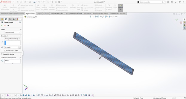
This is how the hinge was made in SolidWorks.
Results
The only hinge that worked correctly was "Test 1"; it can easily bend up to 180°. However, it turned out smaller than expected. An area for improvement is learning how to make it longer, which I believe can be achieved by copying and pasting the pattern more times or using a "Mirror" operation.
In all other tests, I made the mistake of allowing the long cut line to converge with the edge of the piece, causing them to break into several fragments.
Cutting Challenges and Tips
Cutting on the Machine
The first time I attempted to cut with the machine, I made the mistake of using laser number 2 instead of laser number 1, which is the one typically used for cutting. As a result, the piece was only scorched but not cut through. I know it wasn't due to my parameters, as they were the same ones I used later to successfully cut using laser number 1.

Another interesting situation occurred when I sent some pieces to be cut for another project I am working on. I sent everything in the same DXF document using the same parameters (Max Power: 75, Min Power: 70, Speed: 30), yet it only cut through the first half of the pieces. For future occasions, I recommend using slightly more power, as the bed leveling may not be perfectly uniform across all areas due to wear and tear.

Extra Tools
From the instructor's page (Group Assignment: Computer-Controlled Cutting | Ibero Puebla), these are the resources used for the project:
| Resource | Description / Link | Format |
|---|---|---|
| Downloadable Document | Joints Examples - Kerf variation and tests | ZIP File |
| Reference Book | Snap-Fit Book - Types of joints and mechanics | PDF Document |
| Design Tool | Lattice Hinge Design — Choosing Torsional Stress | Web Link |
| Living Hinge Template | Parameterized hinge provided by the instructor | SolidWorks (.SLDPRT) |