What I knew before this week:
- I already knew how to make PCBs thanks to last week, which saved me a lot of time this week.
- I had previously used a microcontroller with a camera for an artificial intelligence workshop, however, it had been a long time since I last practiced it.
Board Design
Board objective: Using a XIAO ESP32-S3 camera with the help of artificial intelligence through image recognition, turn an LED on and off when a human is detected.
Software used
| # | Software | Use |
|---|---|---|
| 1 | KiCad | Board design. |
| 2 | Modsproject | Converting from SVG to the machine file (MonoFab). |
| 3 |
VPanel for SRM-20 Program | Driver |
Operating the MonoFab machine. |
| 4 | Sense Craft | Web platform with the AI model for person detection. |
Materials
| Component | Value / Model | Symbol Library (KiCad) | Footprint |
|---|---|---|---|
| C1 | 10 μF | fab:C_1206 | PCM_fab:C_1206 |
| J1, J2, J3 | Pin Headers | fab:Conn_01x0N_Male | PCM_fab:PinHeader_01xNN… |
| Led1 | LED | fab:LED_1206 | PCM_fab:LED_1206 |
| R1, R2, R3 | 1kΩ | fab:R_1206 | PCM_fab:R_1206 |
| XIAO1 | ESP32-S3 | SeeedStudio_XIAO_ESP32S3 | PCM_fab:SeeedStudio_XIAO_ESP32S3 |
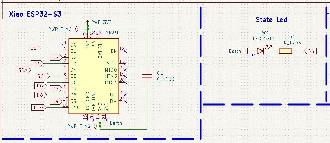
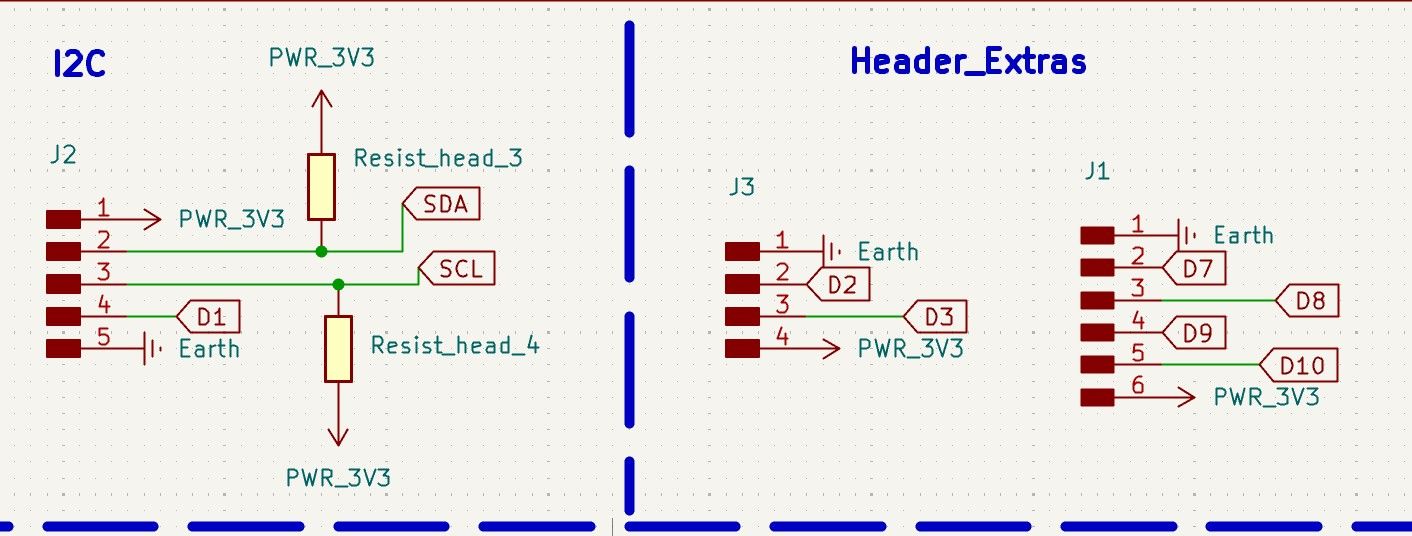
KiCad Schematic Editor
To design the board in KiCad, it was necessary to think about the different areas it would include:
- Microcontroller (XIAO ESP32-S3)
- State LED
- I2C Communication
- Two rows of pin headers for connecting extra components
The board is designed so that other devices or the main board can be connected to the ESP32 via pin headers. It also includes pin headers for I2C communication.
Error I encountered:
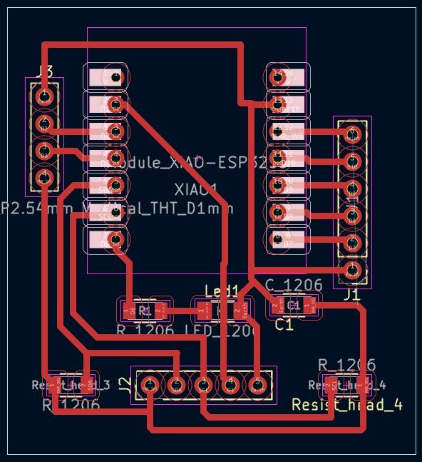
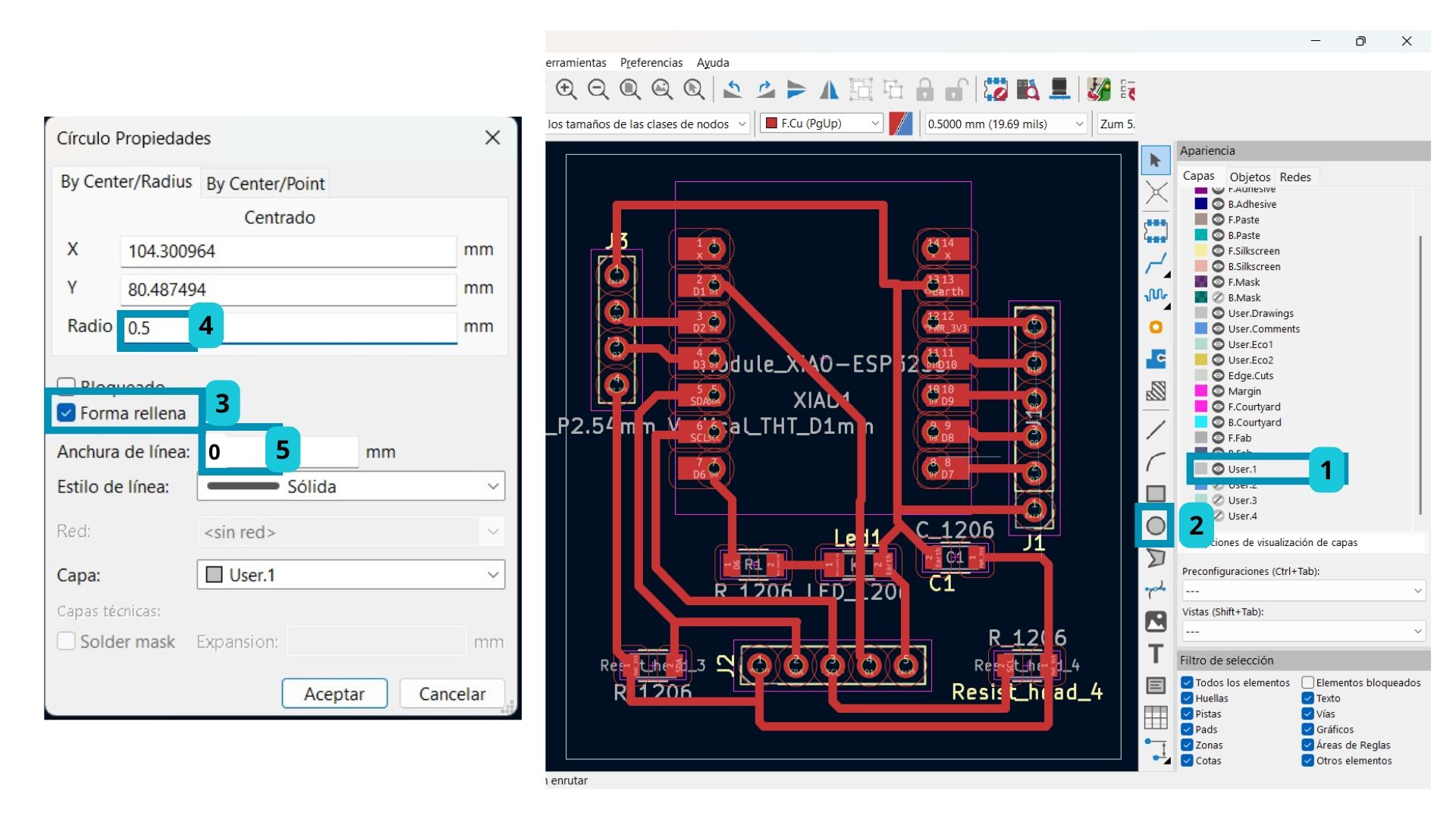
- Since the Drill tool bit is 0.8 mm, it is better to set the radius of the manually drawn circles on the User.1 layer to 0.5 mm. I used 0.4 mm and had a lot of trouble fitting the pin headers into the board.
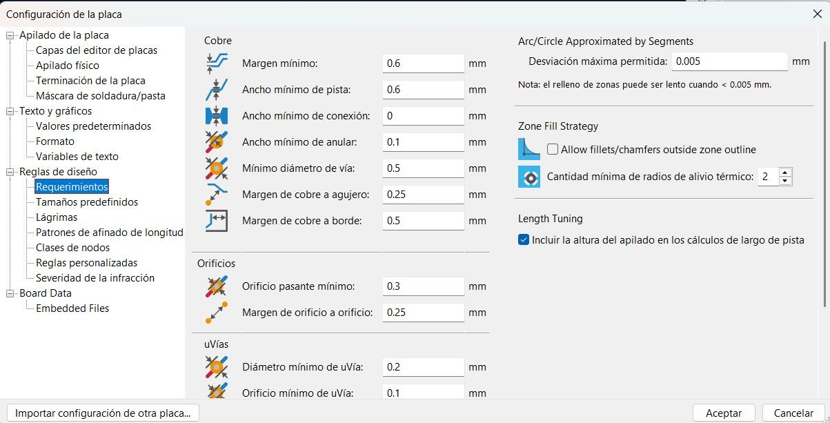
PCB Editor Design
The parameters I used were:
The connected board ended up looking like this:
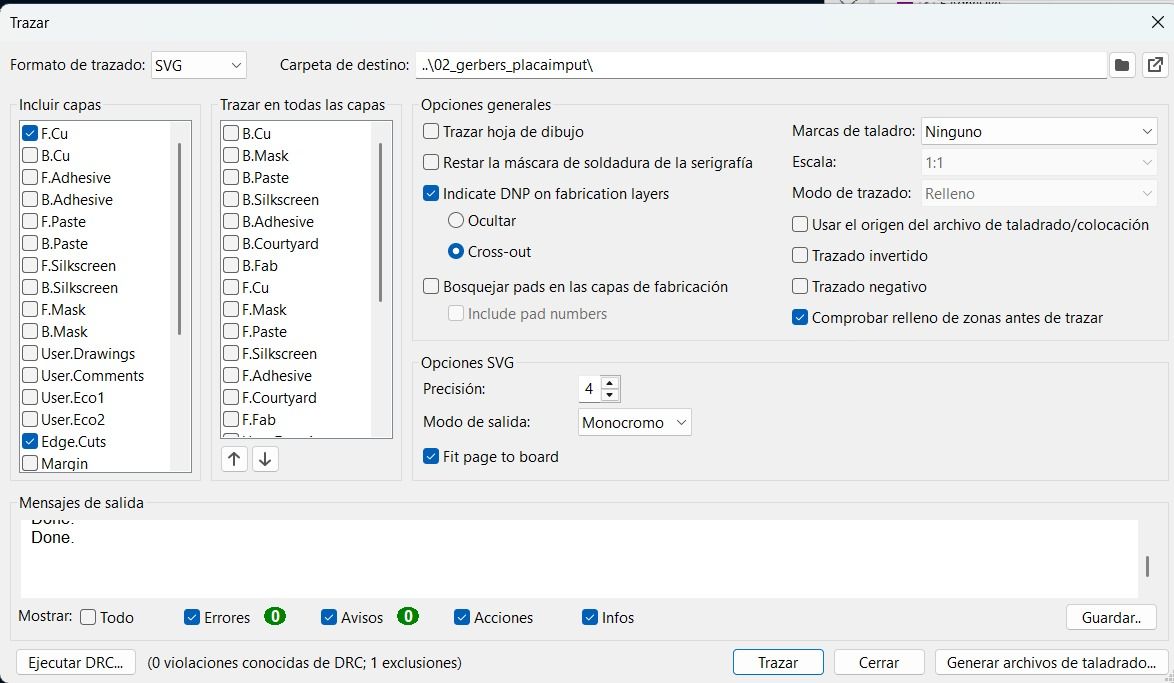
To export the file, I used SVG format this time, activating only the three layers I needed:
| Layer | Use |
|---|---|
| F. Cu | Copper traces |
| Edge. Cuts | External board outline cut |
| User.1 | Drills (done manually) |
The Drills must be done manually. The steps to follow are:
- Select the User.1 layer.
- Click on the circle tool.
- Double-click the circle to open its properties.
- Select the "Filled shape" option and adjust the settings.
Notes:
- Only save the layers you need.
- Any manual changes.
This time I saved the file directly as SVG, so it was not necessary to convert it using Gerber 2 PNG (Gerber2Png | Fablab Kerala).
The steps to export as SVG in KiCad are:
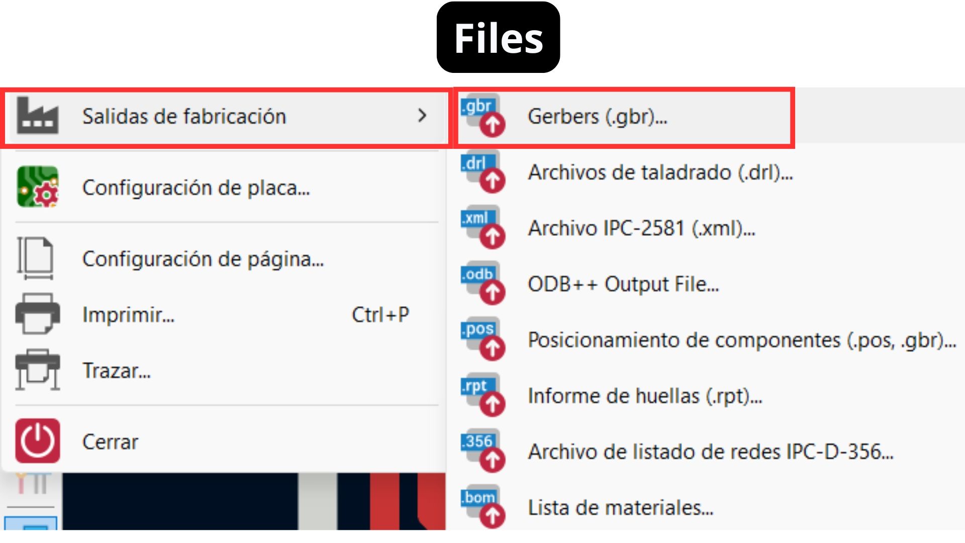
- Go to the File tab.
- Fabrication Outputs.
- Gerbers.
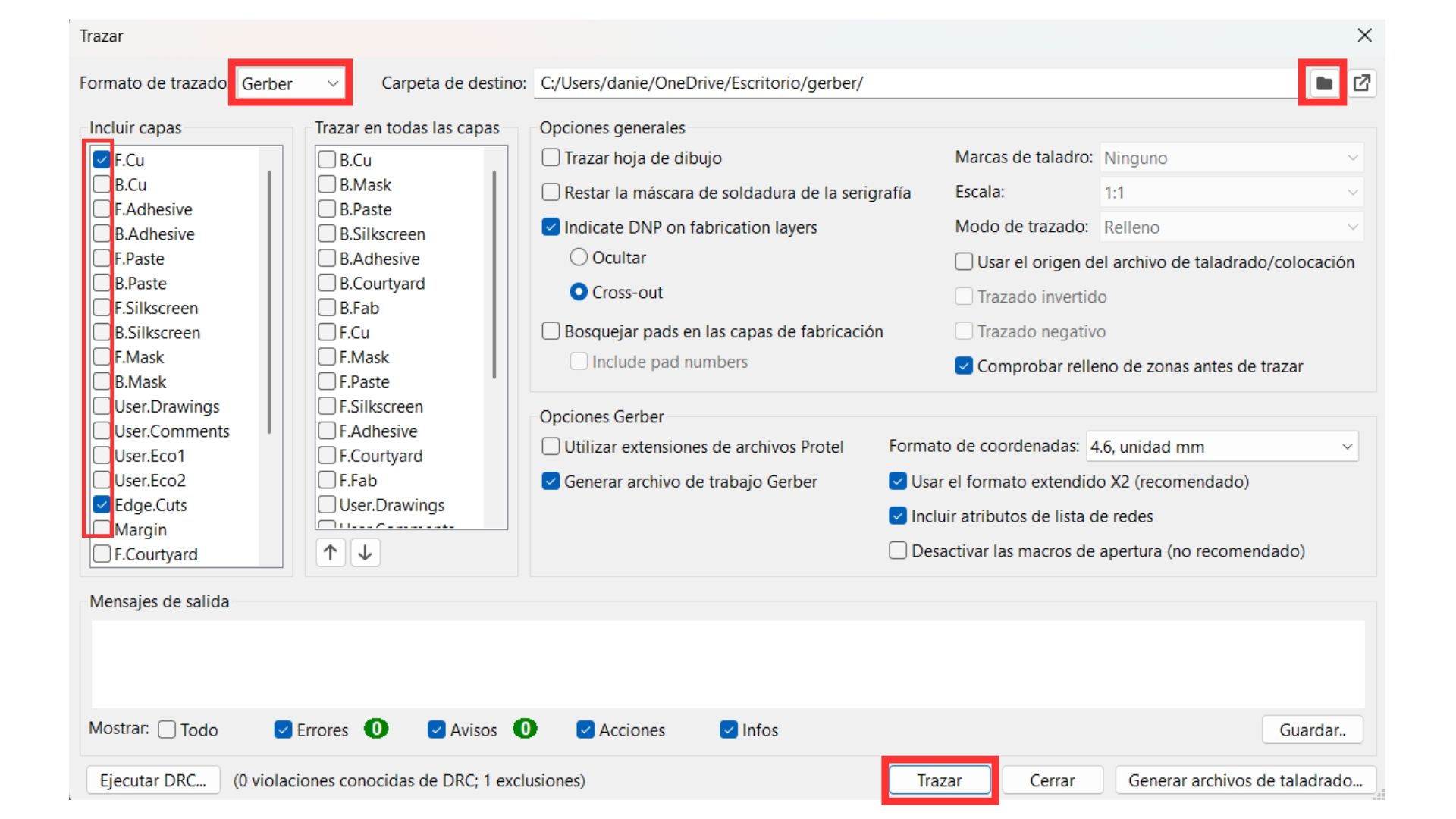
- In the plot format, select SVG instead of Gerber.
- Select the folder to save to.
- Select only the three important layers for the MonoFab (F.Cu, Edge Cuts, User.1).
- Click Plot.
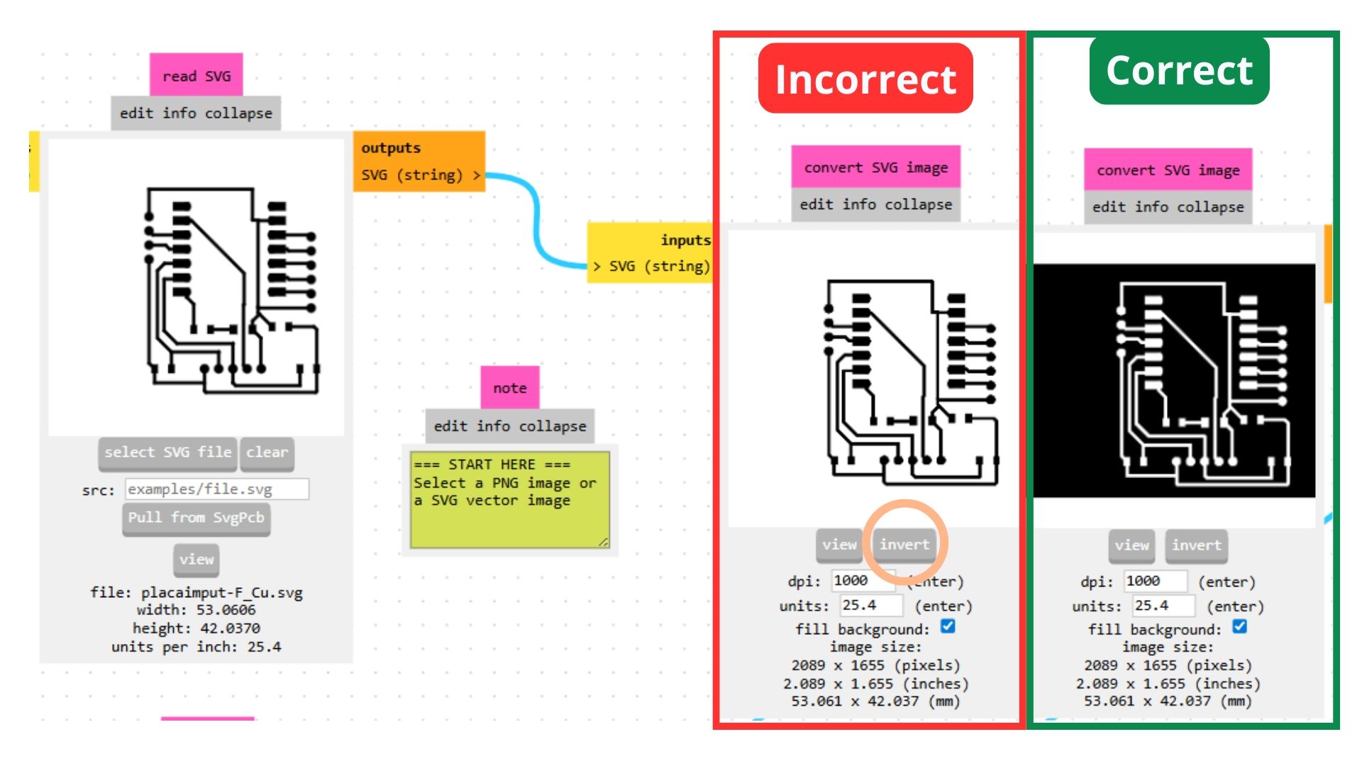
Exporting to Mods
Note: When the file is directly in SVG format...
- It can save all layers separately, which means the holes are captured correctly.
- In the Mods program, you must click the "Invert" button so the program traces what you want (represented by the white area).
- Only invert: Traces — do NOT invert Drills or Edge Cuts.
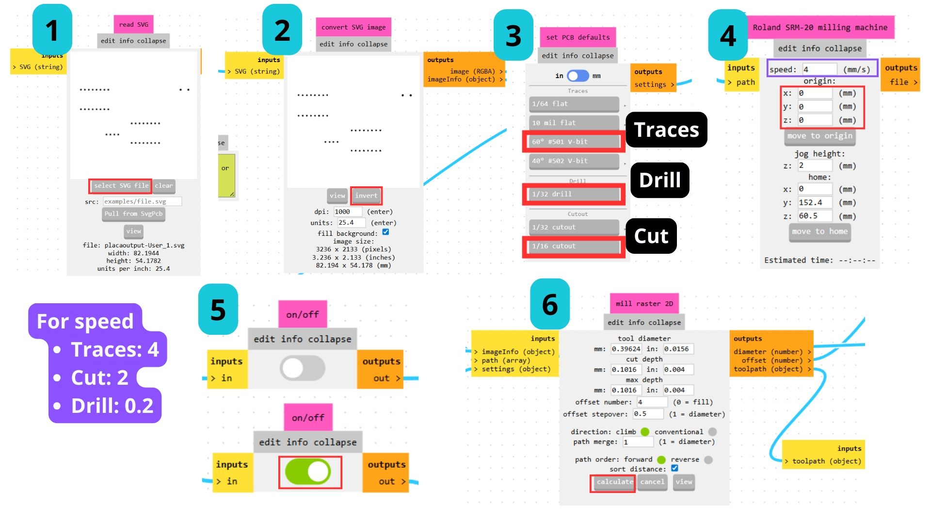
The process for saving the file in the Mods software is shown in the following video. The only difference was when selecting the tool depending on the file being used.
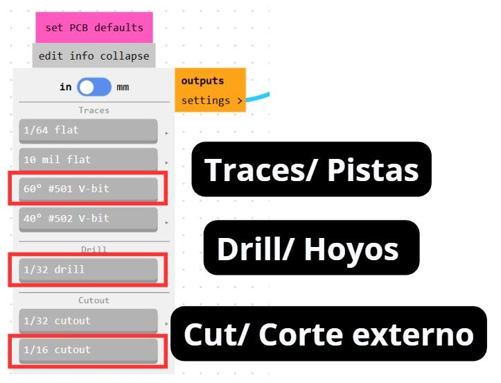
Tools in the Mods software.
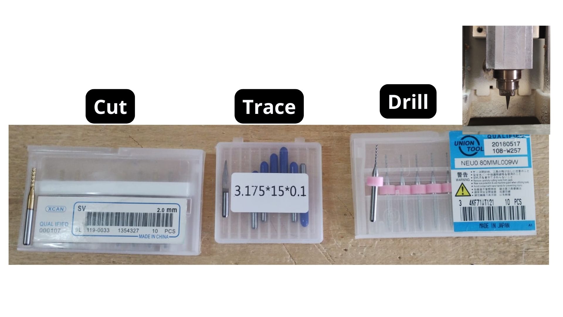
Physical tools of the machine.
With that done, the board can be cut on the MonoFab machine and then soldered.
Extra Code
Once I had the physical board in my hands, I connected it to the Arduino IDE software and uploaded a simple code to make sure the LED was working correctly.
Adding the Microcontroller to Arduino
1. Download the "Additional Boards Manager" for my ESP32
The following video shows how it was done:
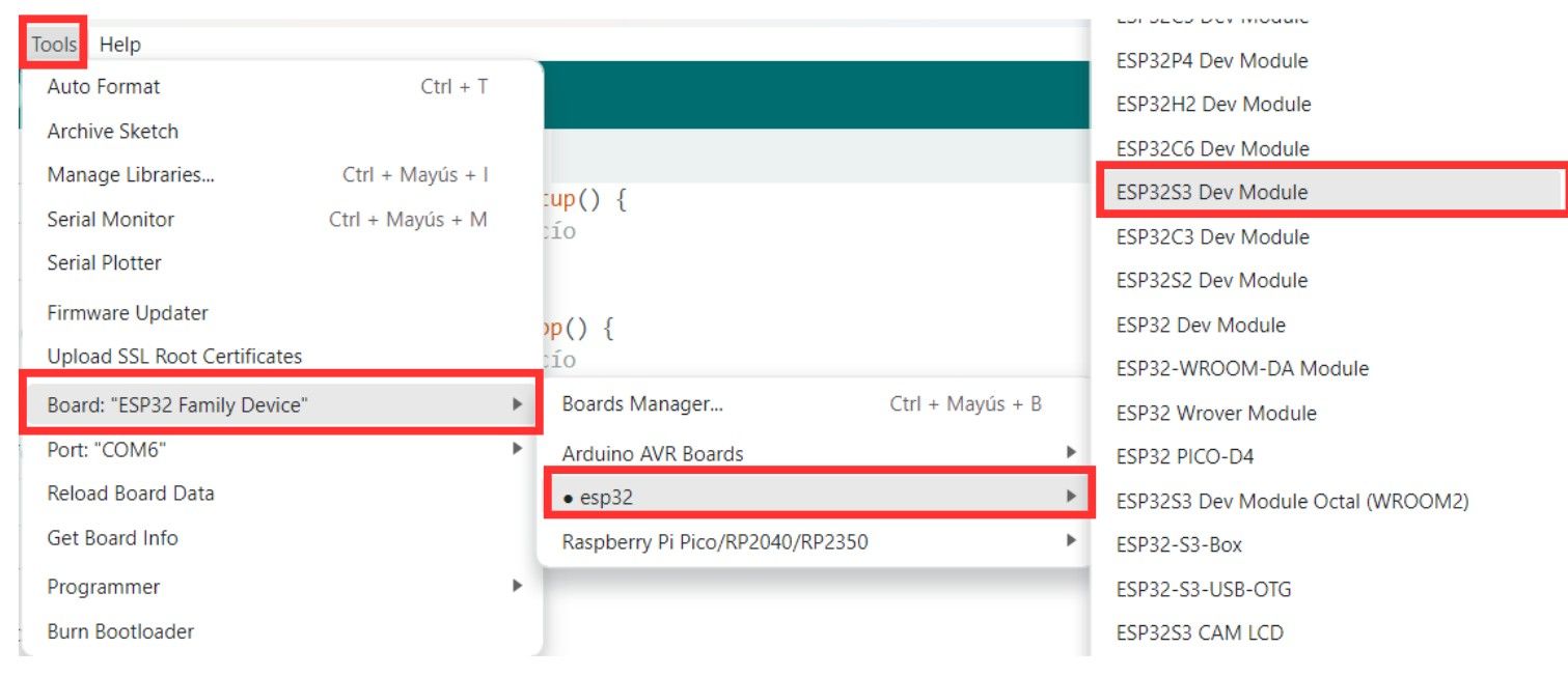
2. Select my ESP32 S3
- Connect the microcontroller via the USB port.
- In the toolbar, select the port where it is connected.
- Tools.
- Board option.
- ESP32.
- Search for the model.
3. Code to test the LED
/*
  Blink for ESP32-S3
  Correctly mapped: Physical Pin D6 -> GPIO 43
*/

// Define the correct pin according to your hardware
const int ledPin = 43;

void setup() {
  // Configure GPIO 43 as output
  pinMode(ledPin, OUTPUT);

  Serial.begin(115200);
  Serial.println("ESP32-S3: Starting blink on GPIO 43 (Pin D6)");
}

void loop() {
  digitalWrite(ledPin, HIGH);   // Turn LED on
  Serial.println("State: ON");
  delay(1000);

  digitalWrite(ledPin, LOW);    // Turn LED off
  Serial.println("State: OFF");
  delay(1000);
}
Sense Craft
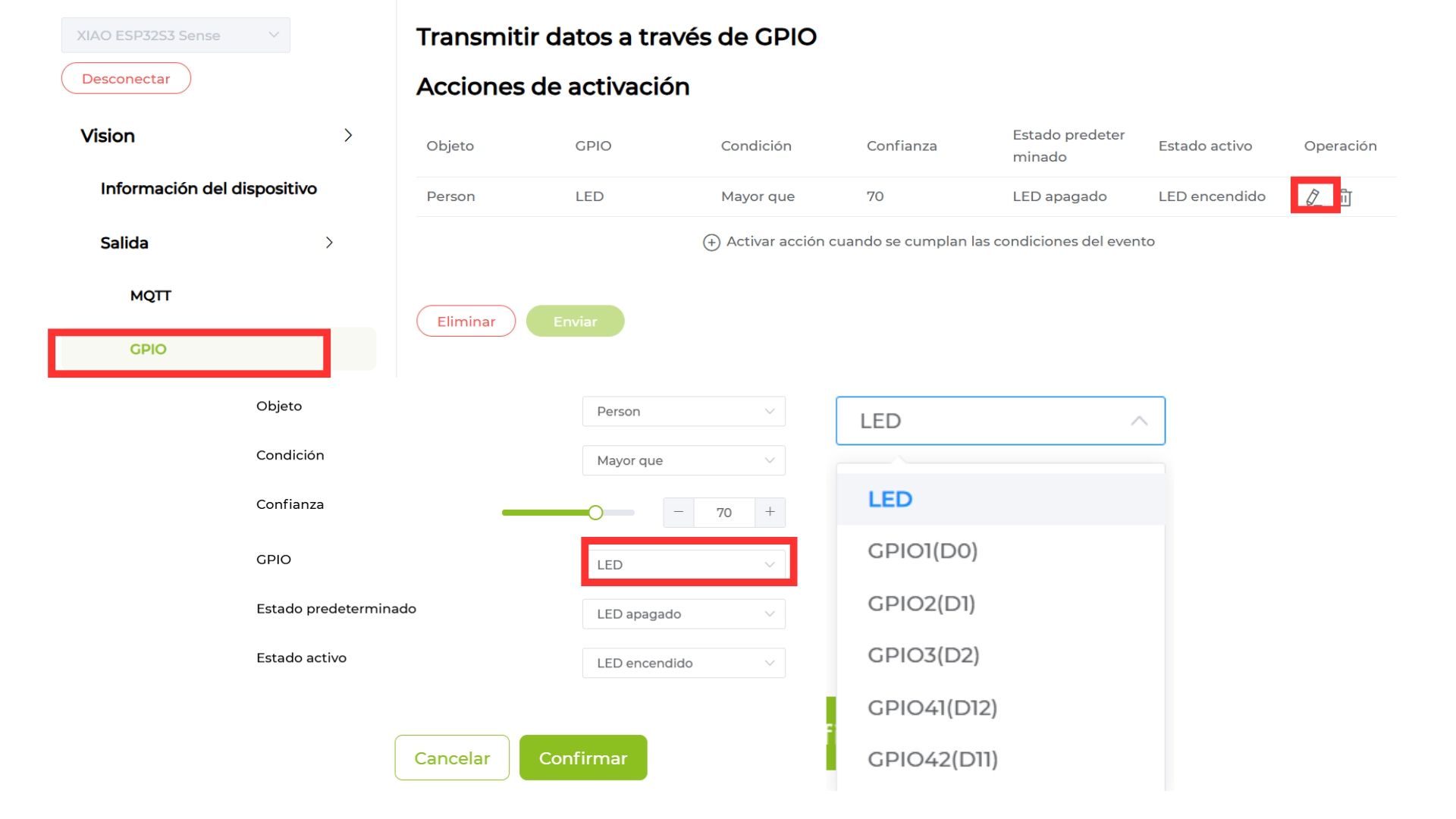
The program I used to load the AI model onto the camera is a web platform called Sense Craft. The steps are:
- Connect the camera using a USB-C cable or whichever connector your microcontroller has.
- Select the device on your computer.
- In the output section, select GPIO.
- Choose the desired trigger actions and the output (in my case, the GPIO to which the LED would be connected). Click Continue.
- Go back to the "Device Information" tab so the AI model activates.
- Enjoy the magic.
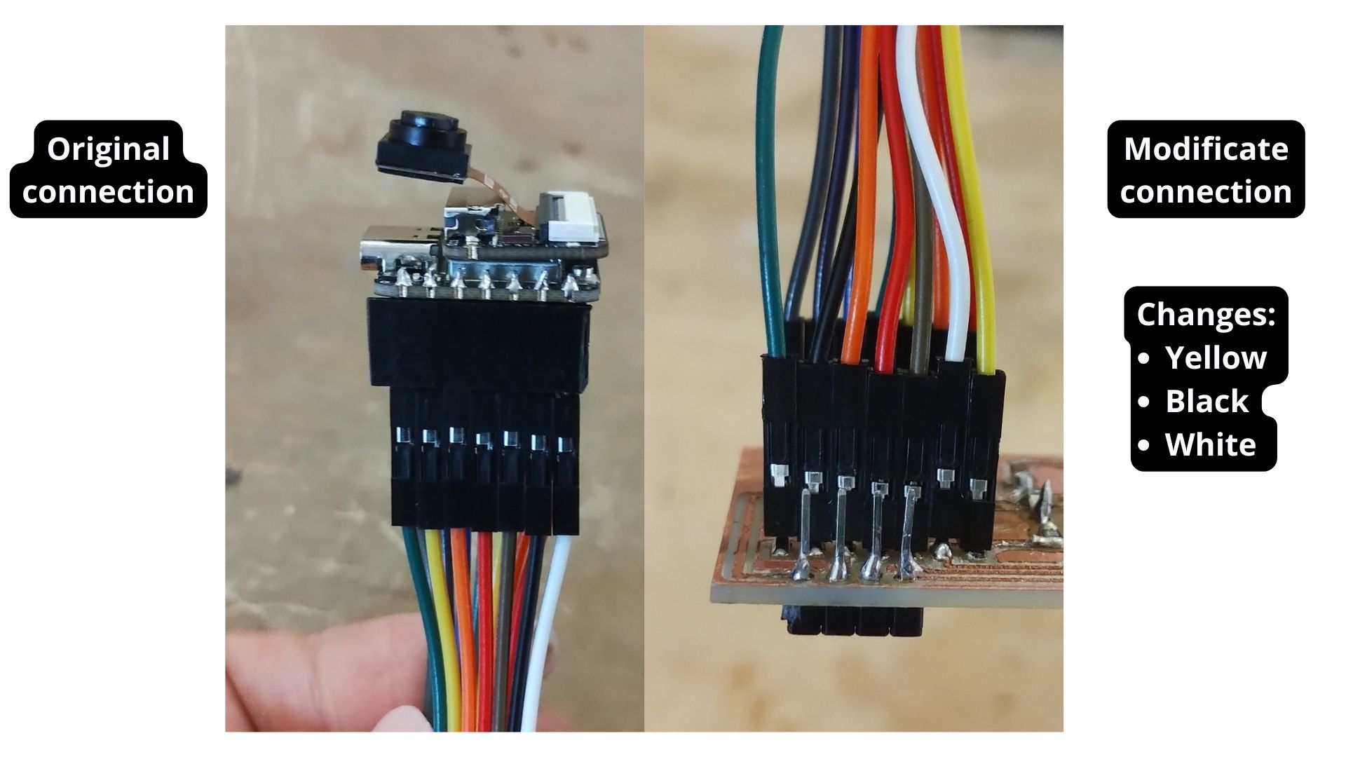
Jumpers Connection
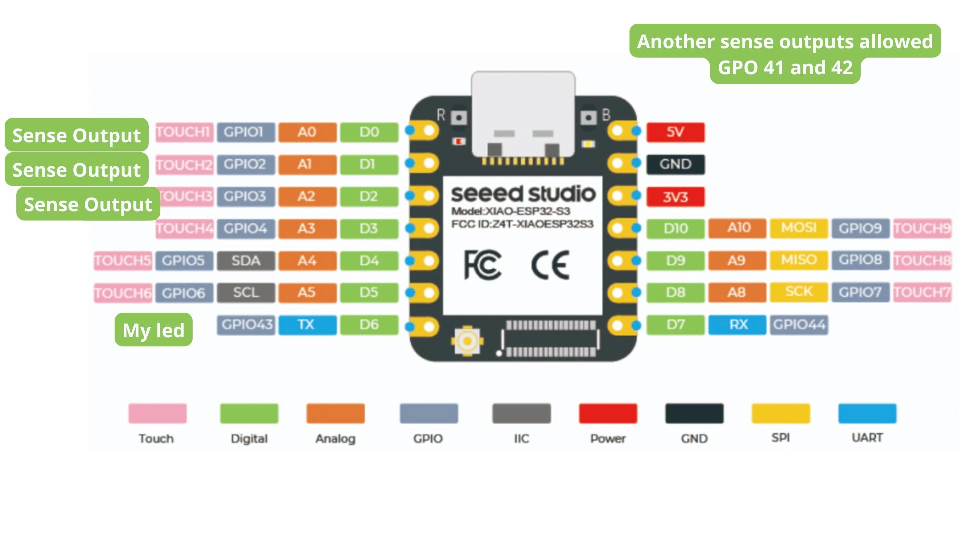
Error I encountered: I did not realize that the Sense Craft page only offers the option to send output to certain pins of a board or Arduino — these are the ones visible in the image below. I had to use jumpers to move the cables to the correct position so that the LED (which was on the D6 output) matched the one I assigned in the Sense Craft program.
Sense Craft AI & Model Operation
To learn a bit more about this model, I did some research and found the following.
1. Architecture and Algorithm: MobileNetV2
The SenseCraft person detection model is based on the MobileNetV2 algorithm. This is a deep neural network architecture specifically designed by Google for mobile devices and resource-constrained hardware (such as the XIAO ESP32S3).
Why MobileNetV2? It uses a technique called "depthwise separable convolutions", which drastically reduces the computational power required without sacrificing too much accuracy, allowing the microcontroller to process images in real time.
2. Model Format and Quantization (INT8 and TF Lite)
For the model to "fit" on the ESP32, two key technologies are used:
- TF Lite (TensorFlow Lite): This is the optimized format for running AI models on embedded systems.
- INT8 Precision (Quantization): This is a very important technical detail. It means the model's weights were converted from complex decimal numbers (FP32) to 8-bit integers. This makes the model much lighter and faster, ideal for the ESP32S3 chip architecture.
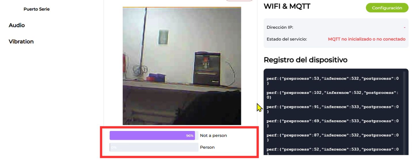
3. Classification
The model analyzes the image and classifies the scene into one of two categories (Classes): "Person" or "Not a person". This model determines presence or absence based on the features learned during its training.
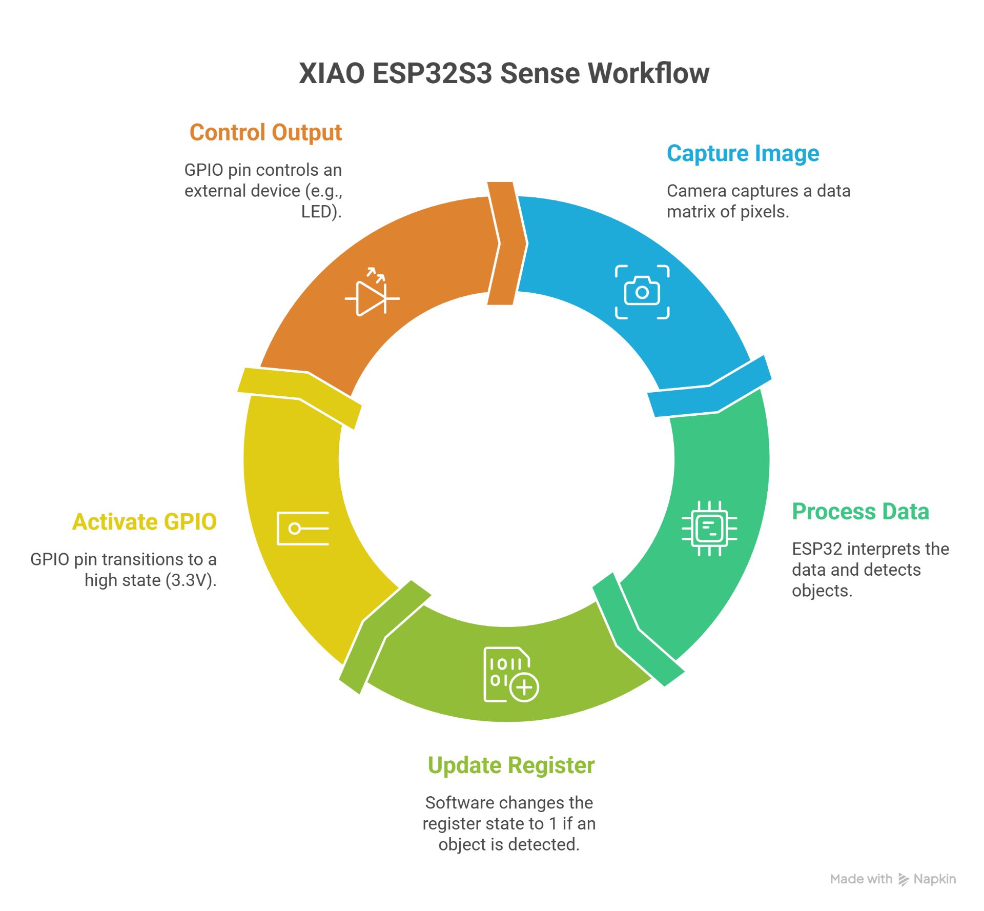
4. Workflow in the XIAO ESP32S3 Sense
Logical and Electrical Connection (Signal Level)
To understand the device as an integrated input-output system, we must map the transduction of physical light into behavioral electrical states across the hardware architecture:
- Optical Transduction & Data Bus: The camera sensor captures environmental light through its photodiode matrix, converting photons into analog electrical charges. An internal ADC (Analog-to-Digital Converter) discretizes these charges into 8-bit digital pixel values. This binary matrix is streamed into the XIAO ESP32S3 internal SRAM via a high-speed parallel camera interface bus.
- Embedded Inference Execution: The ESP32S3 microcontroller channels this raw image buffer into the MobileNetV2 neural network weights stored in flash memory. As the processor executes the matrix multiplications, it generates a probabilistic array. When the mathematical confidence for human presence crosses the 70% threshold, an internal software register toggles a logical flag from
0to1. - Signal-Level Output Transformation: This software flag directly commands the microcontroller's internal peripheral register. The hardware switches an internal Field-Effect Transistor (FET) connected to the physical GPIO pin. This action shifts the electrical potential of the pin from 0V (Logic Low / Ground) to a steady 3.3V (Logic High / VCC). It is this specific 3.3V continuous electrical signal that drives downstream actuators or registers as an active input on testing equipment.
1. The Transformation of Data into Voltage
The camera acts as an Input Sensor and the GPIO as an Output. The technical process is as follows:
- Digital Input (Camera): The camera sends a data matrix (pixels) to the processor through an internal data bus. The signal here is complex and high-speed.
- Processing (Inference): The ESP32 interprets that data. If the model detects a person, the software changes the state of an internal register from 0 (False) to 1 (True).
- Electrical Output (GPIO): That logical 1 is physically translated to the selected GPIO pin (for example, the LED pin or GPIO 1/D0).
- High State: The pin delivers a voltage of 3.3V.
- Low State: The pin drops to 0V (GND).
2. Explanation of GPIO Behavior
Note: It is important to mention that the XIAO ESP32S3 pins operate with 3.3V logic.
- When you configure "Active state: LED on" in the Sense Craft interface, you are instructing the microcontroller to saturate the internal transistor channel of the GPIO to allow current to flow.
- This is the "signal-level connection": it is the transition from a software analysis (person presence) to a measurable electrical pulse.
3. Synchronization and Latency
There is a small delay called inference latency.
- The camera captures.
- The processor calculates (this takes milliseconds).
- The GPIO changes state.
In summary: The camera captures light information and converts it into digital electrical signals that the ESP32 processes using the MobileNetV2 model. Once the inference confirms a detection (Confidence > 70%), the microcontroller switches the logical state of the output register, raising the electrical potential of the selected GPIO pin from 0V to 3.3V (Logic High), allowing external peripherals to be triggered.
Functional Firmware Analysis (Sense Craft AI)
While a standard peripheral test utilizes a basic millisecond delay loop (such as the blink architecture), the deployment firmware operating via Sense Craft establishes a continuous event-driven pipeline optimized for edge processing. The functional code executing on the microchip governs three core routines:
The Core Execution Loop:
- Sensor Polling & Buffer Allocation: The firmware invokes a hardware abstraction layer (HAL) command to read the camera register. It locks a segment of memory (frame buffer) to ensure the frame remains static during the mathematical calculation, avoiding memory corruption.
- Tensorflow Lite Micro Execution: Instead of traditional sequential code, the firmware runs an inference engine loop. It passes the localized frame buffer through the layer nodes of the compiled model graph, computing convolutional operations natively on the ESP32S3's vector instructions to minimize power consumption.
- Conditional Register Writing: The conditional logic evaluates the model's output array. If
output_score[human_class] > 0.70, the code calls the low-level functiongpio_set_level(GPIO_NUM_X, 1), instantly altering the hardware register state. If the condition is false, it writes a0to clear the signal line.
Code Analysis
This operational architecture ensures that peripheral state changes are directly linked to real-time algorithmic confidence metrics rather than deterministic software timers.
In the bottom-right corner, you can see the code the program is currently running.
To understand what is happening inside my device's "brain", I analyzed the performance data it outputs while running. It is like watching the processor's "heartbeat" as it tries to recognize me.
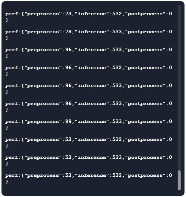
This is how you can see the code running.
| Process Stage | Estimated Time | What is happening? (Technical explanation) | Analogy to understand it |
|---|---|---|---|
| Pre-processing | 90 ms | The camera adjusts the size and format of the image so the AI can process it. | Like squinting your eyes to focus on something far away. |
| Inference | 533 ms | The device's "brain" analyzes the image using the MobileNetV2 algorithm to search for human patterns. | The time it takes you to recognize a friend's face in a crowd. |
| Post-processing | < 1 ms | The final logical response is generated based on the previous analysis. | The instant decision to say "Hello!" when you recognize the person. |
| Total Time | ~623 ms | Complete cycle from the moment light enters the lens to when an action is generated. | An eye blink lasts about 300–400ms — this is almost just as fast! |
In summary: The entire process, from the camera seeing me to deciding to turn on the LED, takes about 630 milliseconds. This is incredibly fast for such a small device, allowing detection to work almost instantly when someone appears in front of the camera.
Results
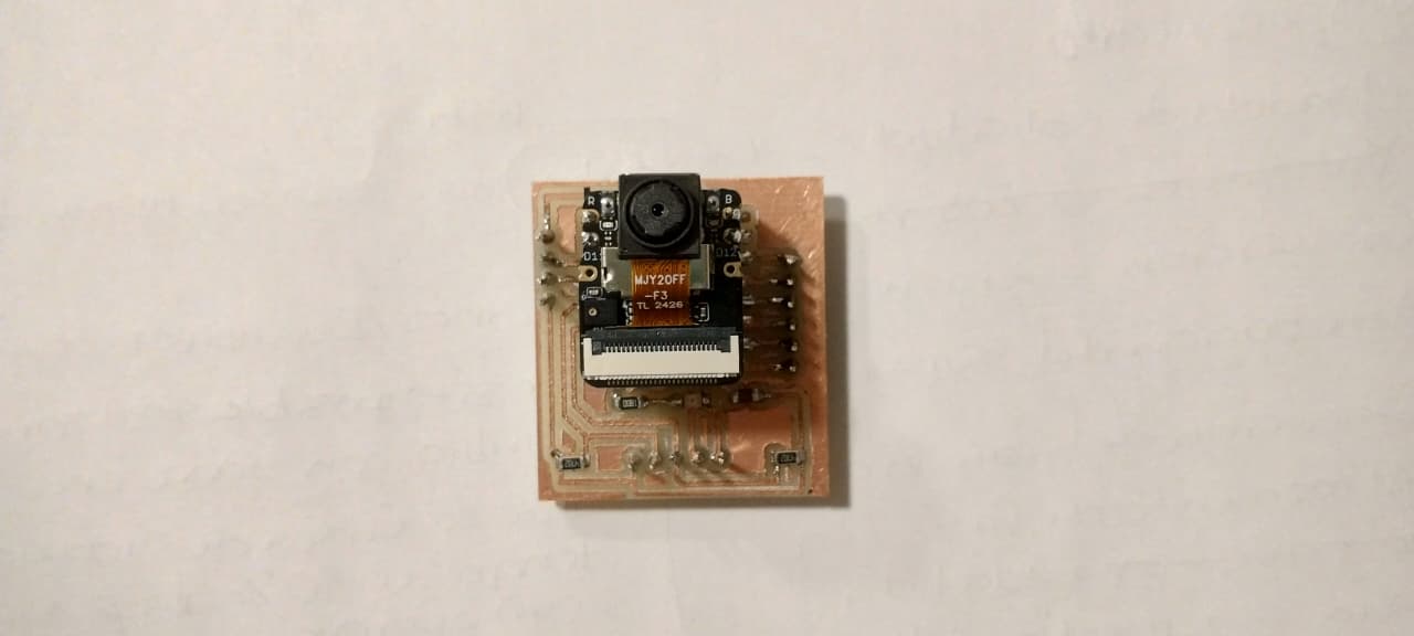
Soldered board.
Camera working with the AI model.
Board in operation while detecting a person.
Reflections
Individual Reflection: Signal Measurement (Multimeter vs. Oscilloscope)
I feel that I learned to use tools that I had been wanting to learn for a long time, specifically:
- The Multimeter (Static Probing): I used it to verify the continuity of my connections and to ensure that the supply voltage on my XIAO ESP32S3 was 3.3V — in other words, to check that the board had continuity. It is essential for ruling out hardware errors (short circuits or loose wires) before uploading code.
- The Oscilloscope (Dynamic Probing): It allowed me to "see" the signal. I learned to adjust the Trigger and Time Scale to observe how the output signal of a sensor changes state. It was eye-opening to see the electrical noise and how the digital signal switches cleanly between logical voltage levels. Although I have only used the oscilloscope once and with guidance, I consider it a vital tool for understanding how signals work in a more applied way.
Group Assignment Learnings
The biggest takeaway for me is that every sensor is different, and there is no magic formula for connecting everything the same way — which means datasheets will be your best friends. I also learned more about:
- Analog Signals: I learned that sensors like the pulse sensor deliver continuous voltage variations that the microcontroller must translate using an ADC (Analog-to-Digital Converter).
- Communication Protocols: I understood that more complex sensors use protocols such as I2C or SPI. Documenting this helped me understand why sensors sometimes don't respond if pull-up resistors are missing or if the hexadecimal addresses are incorrect.
Files I used this week
01_kicad_placainput.zip
Input Devices Files
The following files are included in this package:
- placainput (Project)
- placainput (PCB)
- placainput (Schematic)
- placainput.kicad_prl
02_svg.zip
Input Devices Files
The following files are included in this package:
- placainput-Edge_Cuts
- placainput-Edge_Cuts
- placainput-User_1
03_Monofab_input.zip
Input Devices Files
The following files are included in this package:
- Cut.rml
- Drill.rml
- Trace.rml
Arduino_code_blink.zip
Arduino Code Files
The following files are included in this package:
- Arduino_code_Blink.ino