Week 11 — Networking and Communications
Assignment
Individual: Design, build, and connect wired or wireless node(s) with network or bus addresses and local input and/or output device(s).
Group: Send a message between two projects.
Here is my plan for the week:

Group Assignment
For this weeks group assignment you can click here: Group Assignment
What I Built
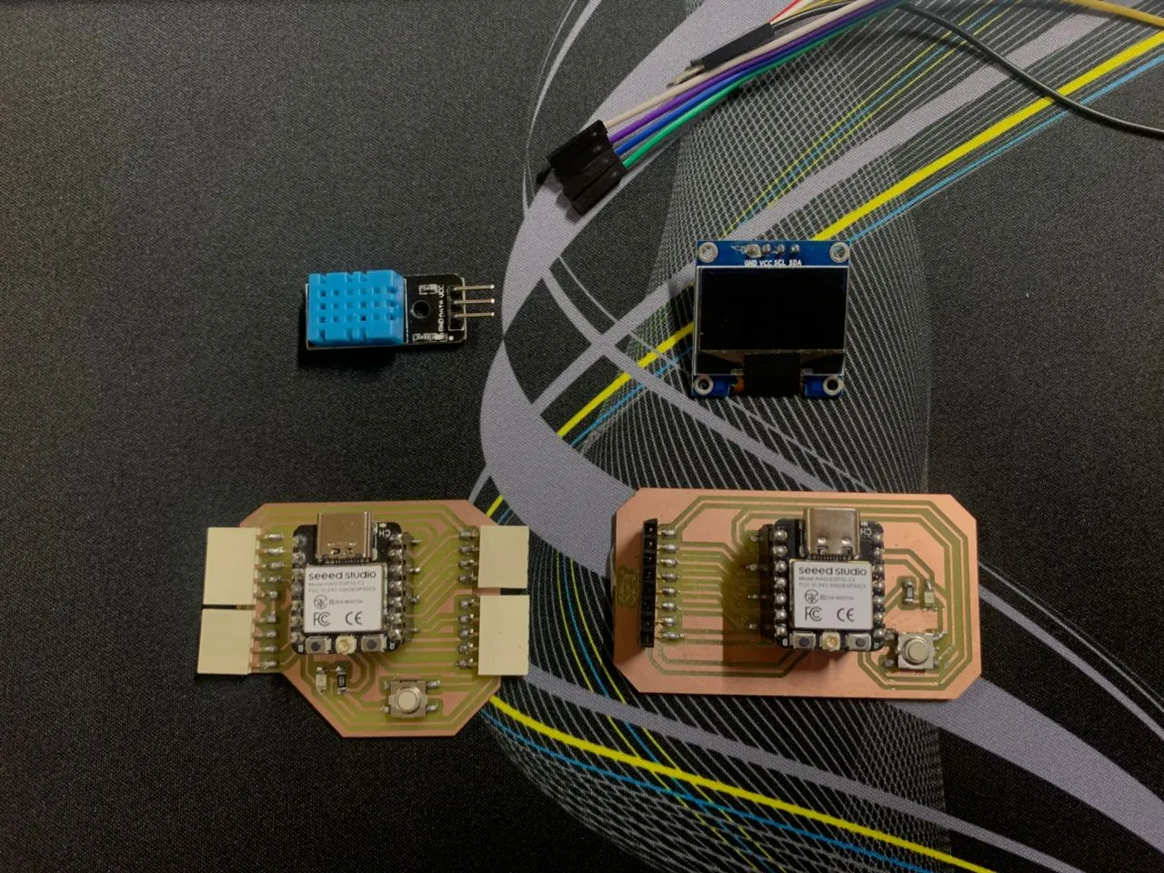
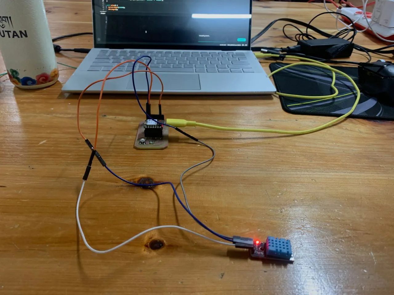
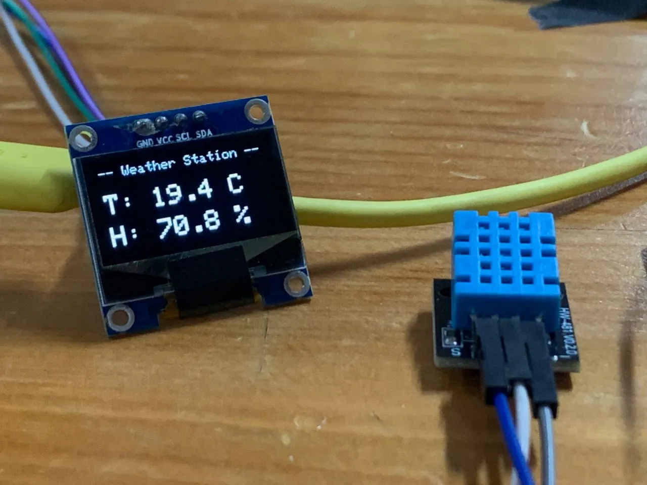
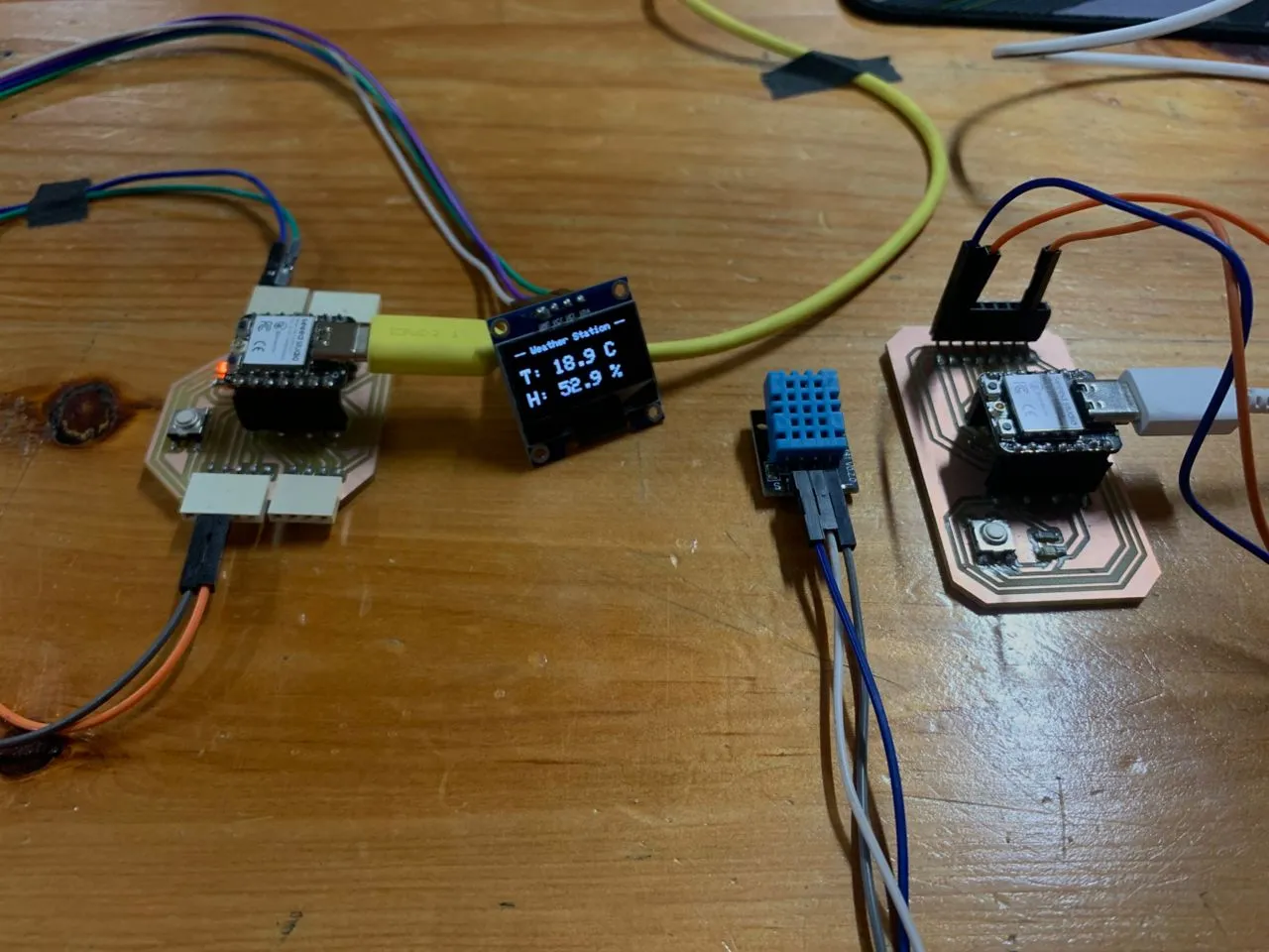
This week I built a wireless weather station using two XIAO ESP32-C3 boards — one reads temperature and humidity from a DHT11 sensor and sends the data wirelessly, the other receives it and displays it live on a 0.96" OLED screen. I used two protocols: ESP-NOW for the wireless communication between the boards, and I2C for the OLED display on the receiver side.
Understanding the Protocols
Before jumping in, I want to quickly explain the protocols I used because the assignment specifically asks for network or bus addresses — and I want to be clear about what those are in my project.
UART is the simplest serial protocol — just two wires, TX and RX, no clock. Both devices agree on a baud rate beforehand and that's how they stay in sync. I've been using this every time I open the Serial Monitor in Arduino — that's UART between my ESP32 and my laptop.
I2C uses two wires — SDA (data) and SCL (clock). It's synchronous, meaning one device drives a clock signal and everyone follows it. What makes I2C special is addressing — every device on the bus has a unique 7-bit address. My OLED's I2C address is 0x3C, which is how the ESP32 knows which device to talk to even if multiple things share the same two wires.
SPI is faster than I2C, uses four wires (MOSI, MISO, SCK, CS), and selects devices using a chip select pin. I used this with my TFT display in Week 10.
ESP-NOW is a wireless protocol by Espressif that lets ESP32 boards talk directly to each other without needing a WiFi router. Each ESP32 has a unique MAC address — a 6-byte hardware ID burned into the chip at the factory. The sender stores the receiver's MAC address and sends data packets directly to it. No internet, no router, just board to board. The MAC address is the "network address" this week's assignment is asking for.
The Plan
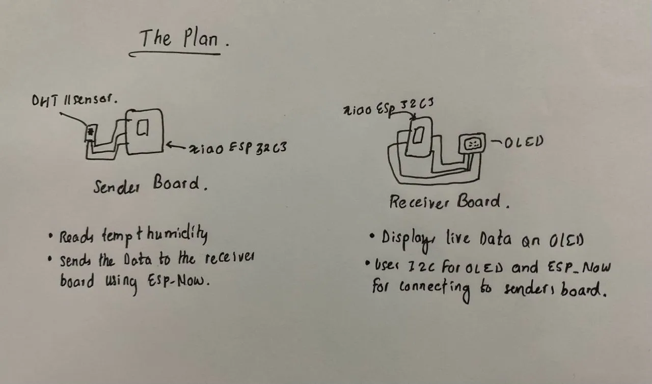
Both protocol requirements are covered — ESP-NOW handles the wireless network layer between boards, and I2C handles the wired connection between the receiver and the OLED.
Wiring
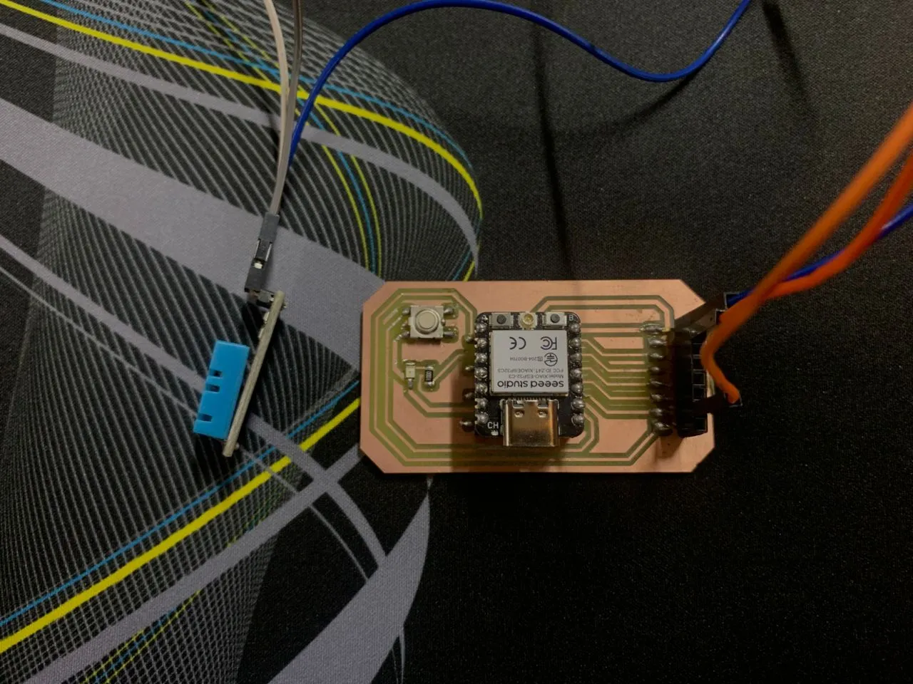
Sender board — DHT11 to XIAO ESP32-C3
| DHT11 Pin | XIAO ESP32-C3 |
|---|---|
| VCC | 3.3V |
| GND | GND |
| DATA | D2 (GPIO4) |
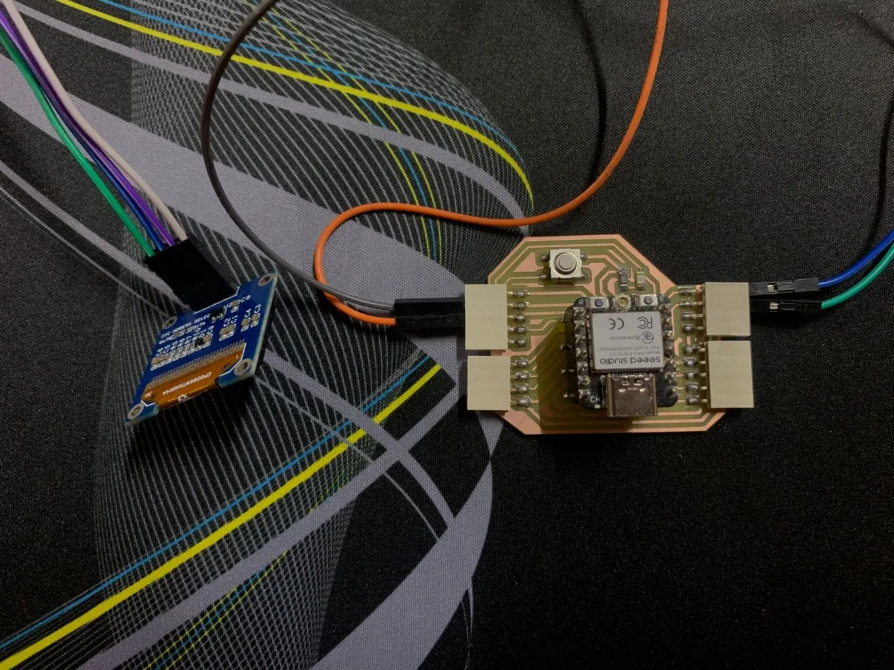
Receiver board — OLED to XIAO ESP32-C3
| OLED Pin | XIAO ESP32-C3 |
|---|---|
| VCC | 3.3V |
| GND | GND |
| SDA | D4 (GPIO6) |
| SCL | D5 (GPIO7) |
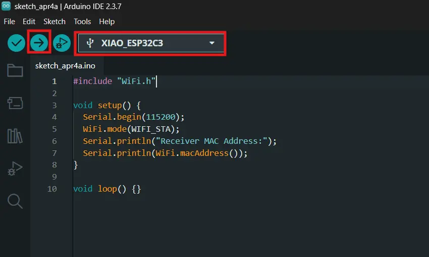
Getting the Receiver's MAC Address
The first thing I had to do was get the MAC address of the receiver board. ESP-NOW needs it hardcoded in the sender so it knows exactly where to send the data. I uploaded a simple sketch to the receiver and read the address from Serial Monitor.
I generated this code using Claude AI with the following prompt:
"I am doing Fab Academy Week 11 networking and communications. I have two XIAO ESP32-C3 boards. I need a simple sketch to get the MAC address of my receiver board so I can use it for ESP-NOW. Factcheck before you answer."
Here is the code that Claude came up with:
#include <WiFi.h>

void setup() {
  Serial.begin(115200);

  // CRITICAL FOR XIAO ESP32-C3: Wait for the serial port to connect.
  // Without this, the code runs before the Serial Monitor is ready.
  while (!Serial) {
    delay(10);
  }

  // Set Wi-Fi to Station mode to ensure we get the correct ESP-NOW MAC address.
  WiFi.mode(WIFI_STA);

  Serial.println();
  Serial.println("=====================================");
  Serial.print("Receiver MAC Address: ");
  Serial.println(WiFi.macAddress());
  Serial.println("=====================================");
}

void loop() {
  // Nothing to do here
}
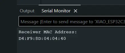
The receiver's MAC address came out as D4:F9:8D:04:04:40. I plugged this into the sender code as:
Testing the Sensor First
Before adding any wireless stuff I tested the DHT11 alone on the sender to make sure it was reading correctly. Good habit — test each part in isolation before combining everything.
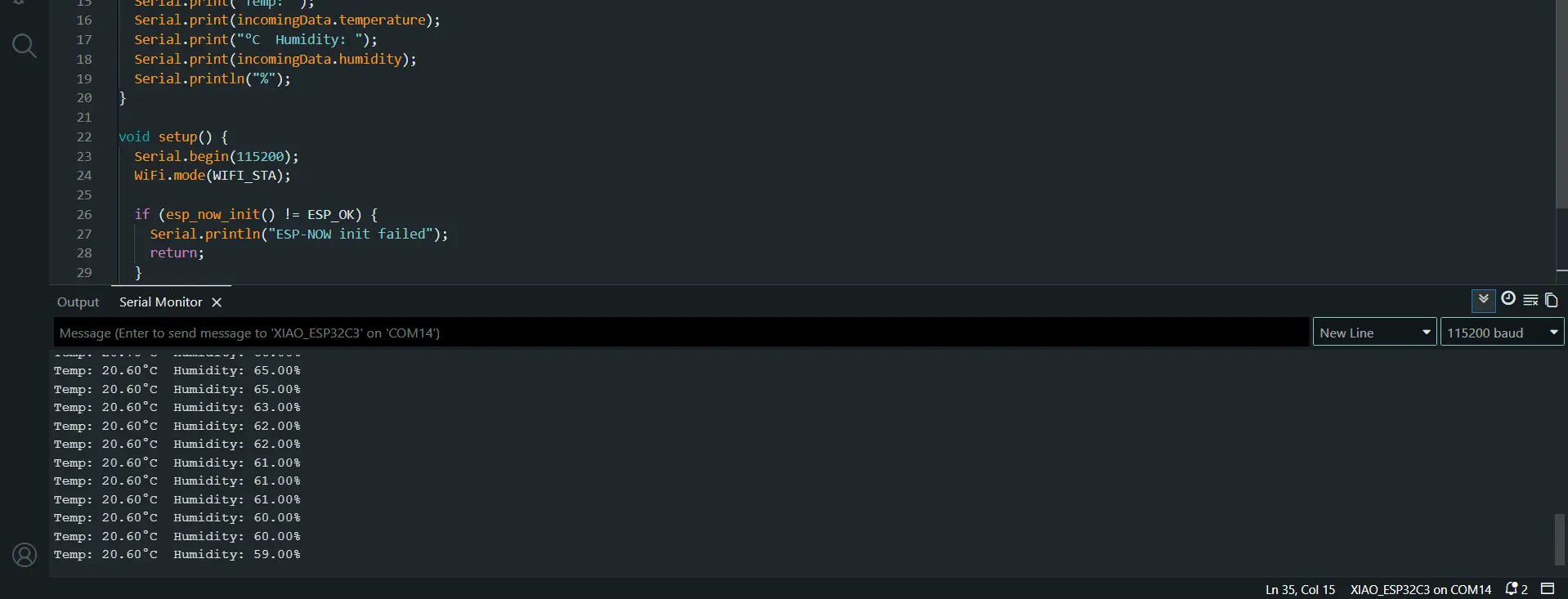
Sensor was working fine. Room was around 19-20°C which matched what I expected.
Sender Code
The sender reads DHT11 every 3 seconds and packs the temperature and humidity into a struct, then fires it off via ESP-NOW to the receiver's MAC address. I use 3 seconds instead of 2 because the DHT11 has a hardware limitation — it can only take a fresh reading every 2 seconds minimum, and right on that edge it sometimes fails. 3 seconds gives it enough breathing room.
I also ran into a compile error with the ESP-NOW send callback. In ESP32 Arduino core 3.x, the callback signature changed — it now takes wifi_tx_info_t* instead of uint8_t*. So the onSent function had to be updated to match.
I generated this code using Claude AI with the following prompt:
"Write an Arduino sender sketch for XIAO ESP32-C3 using ESP-NOW. It should read temperature and humidity from a DHT11 connected to D2 (GPIO4) and send the data wirelessly to a receiver board with MAC address D4:F9:8D:04:04:40. Factcheck the code before you answer me."
When I tried to compile I got a callback signature error. I debugged it with Claude using the prompt:
"I am getting this error: invalid conversion from void ()(const uint8_t, esp_now_send_status_t) to esp_now_send_cb_t. I am using ESP32 Arduino core 3.x on a XIAO ESP32-C3. Fix it and explain why."
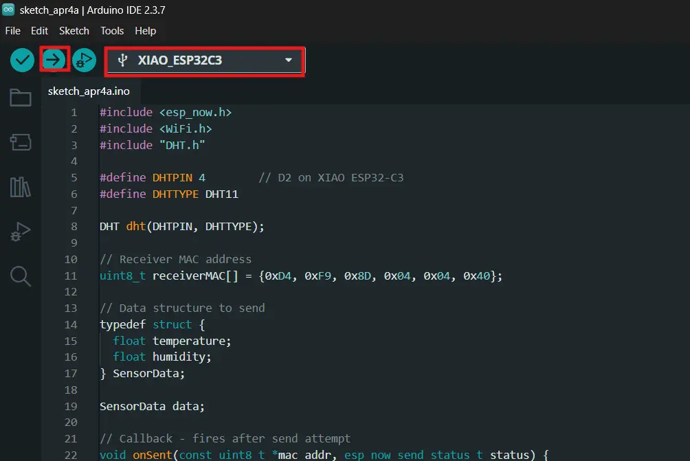
#include <esp_now.h>
#include <WiFi.h>
#include "DHT.h"
#define DHTPIN 4 // D2 on XIAO ESP32-C3
#define DHTTYPE DHT11
DHT dht(DHTPIN, DHTTYPE);
// Receiver MAC address
uint8_t receiverMAC[] = {0xD4, 0xF9, 0x8D, 0x04, 0x04, 0x40};
// Data structure to send
typedef struct {
float temperature;
float humidity;
} SensorData;
SensorData data;
// Callback - fires after send attempt
// Note: core 3.x changed the signature to wifi_tx_info_t*
void onSent(const wifi_tx_info_t *tx_info, esp_now_send_status_t status) {
if (status == ESP_NOW_SEND_SUCCESS) {
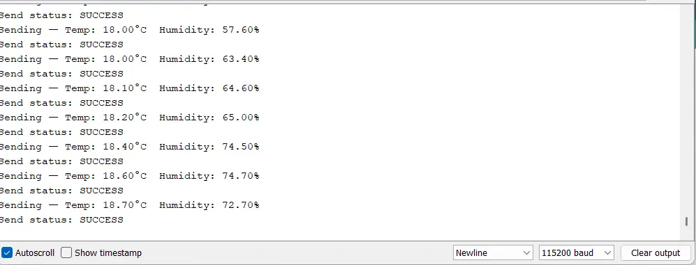
Serial.println("Send status: SUCCESS");
} else {
Serial.println("Send status: FAILED — retrying...");
esp_now_send(receiverMAC, (uint8_t *)&data, sizeof(data));
}
}
void setup() {
Serial.begin(115200);
dht.begin();
delay(2000); // Let DHT11 stabilize on boot
WiFi.mode(WIFI_STA);
if (esp_now_init() != ESP_OK) {
Serial.println("ESP-NOW init failed");
return;
}
esp_now_register_send_cb(onSent);
esp_now_peer_info_t peerInfo = {};
memcpy(peerInfo.peer_addr, receiverMAC, 6);
peerInfo.channel = 0;
peerInfo.encrypt = false;
if (esp_now_add_peer(&peerInfo) != ESP_OK) {
Serial.println("Failed to add peer");
return;
}
Serial.println("Sender ready");
}
void loop() {
float temp = dht.readTemperature();
float hum = dht.readHumidity();
// Validate reading before sending
if (isnan(temp) || isnan(hum)) {
Serial.println("DHT11 read failed — skipping");
delay(3000);
return;
}
data.temperature = temp;
data.humidity = hum;
Serial.print("Sending — Temp: ");
Serial.print(data.temperature);
Serial.print("°C Humidity: ");
Serial.print(data.humidity);
Serial.println("%");
esp_now_send(receiverMAC, (uint8_t *)&data, sizeof(data));
delay(3000); // 3s gives DHT11 enough time for a fresh reading
}
Key Parts — Sender
The SensorData struct is the "package" that gets sent wirelessly:
ESP-NOW sends raw bytes, it has no idea what data type is being transmitted. Packing both readings into one struct means the whole thing can be cast to a byte array with (uint8_t *)&data and sent in one shot. The receiver uses the exact same struct definition to unpack it on the other side. If the two structs don't match, the data comes out garbled.
The onSent callback fires automatically after every send attempt:
void onSent(const wifi_tx_info_t *tx_info, esp_now_send_status_t status) {
if (status == ESP_NOW_SEND_SUCCESS) {
Serial.println("Send status: SUCCESS");
} else {
Serial.println("Send status: FAILED — retrying...");
esp_now_send(receiverMAC, (uint8_t *)&data, sizeof(data));
}
}
This part of the code is: esp_now_send() returns immediately and this callback reports back whether it worked. If it failed, it retries once right there. The isnan() check earlier in the loop catches bad DHT11 readings before they even reach this point — if either value comes back as NaN the whole cycle is skipped rather than sending garbage data to the receiver.
Receiver Code
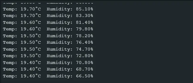
The receiver sits and waits. When ESP-NOW data arrives, a callback function fires, unpacks the struct, and immediately updates the OLED via I2C. The display shows "Waiting for data.." on boot and switches to live readings as soon as the first packet arrives.
I generated this code using Claude AI with the following prompt:
"Write an Arduino receiver sketch for XIAO ESP32-C3 using ESP-NOW. When data arrives it should display the temperature and humidity on a 0.96 inch OLED connected via I2C. The OLED I2C address is 0x3C. Factcheck the code before you answer me."
#include <esp_now.h>
#include <WiFi.h>
#include <Wire.h>
#include <Adafruit_GFX.h>
#include <Adafruit_SSD1306.h>
#define SCREEN_WIDTH 128
#define SCREEN_HEIGHT 64
#define OLED_RESET -1
#define SCREEN_ADDRESS 0x3C // I2C address of the OLED
Adafruit_SSD1306 display(SCREEN_WIDTH, SCREEN_HEIGHT, &Wire, OLED_RESET);
// Must match sender struct exactly
typedef struct {
  float temperature;
  float humidity;
} SensorData;
SensorData incomingData;
// Callback - fires when data arrives via ESP-NOW
void onReceive(const esp_now_recv_info_t *recv_info, const uint8_t *data, int len) {
memcpy(&incomingData, data, sizeof(incomingData));
Serial.print("Temp: ");
Serial.print(incomingData.temperature);
Serial.print("°C Humidity: ");
Serial.print(incomingData.humidity);
Serial.println("%");
// Update OLED display via I2C
display.clearDisplay();
display.setTextSize(1);
display.setTextColor(SSD1306_WHITE);
display.setCursor(0, 0);
display.println("-- Weather Station --");
display.setTextSize(2);
display.setCursor(0, 20);
display.print("T: ");
display.print(incomingData.temperature, 1);
display.println(" C");
display.setCursor(0, 44);
display.print("H: ");
display.print(incomingData.humidity, 1);
display.println(" %");
display.display();
}
void setup() {
Serial.begin(115200);
WiFi.mode(WIFI_STA);
// Init OLED over I2C
if (!display.begin(SSD1306_SWITCHCAPVCC, SCREEN_ADDRESS)) {
Serial.println("OLED init failed");
while (true);
}
display.clearDisplay();
display.setTextSize(1);
display.setTextColor(SSD1306_WHITE);
display.setCursor(0, 28);
display.println(" Waiting for data..");
display.display();
// Init ESP-NOW
if (esp_now_init() != ESP_OK) {
Serial.println("ESP-NOW init failed");
return;
}
esp_now_register_recv_cb(onReceive);
Serial.println("Receiver ready");
}
void loop() {}
Key Parts — Receiver
The entire logic lives inside the onReceive callback:
void onReceive(const esp_now_recv_info_t *recv_info, const uint8_t *data, int len) {
  memcpy(&incomingData, data, sizeof(incomingData));
  ...
}
When an ESP-NOW packet arrives, the ESP32 fires this function and passes a raw byte pointer. The memcpy line copies those bytes directly into the incomingData struct. This is exactly why the struct on both boards has to be identical — memcpy doesn't care about data types, it just copies bytes in order. If the layout differs on either side, the temperature bytes land in the humidity slot and vice versa.
The loop() function is completely empty — there's nothing to poll. The callback handles everything the moment data arrives.
Results
Both boards running, data flying wirelessly, OLED updating live every 3 seconds. The OLED talks to the ESP32 over I2C at address 0x3C, and the two boards communicate via ESP-NOW using the receiver's MAC address D4:F9:8D:04:04:40 as the network address.
What I Learned
The ESP32 core 3.x callback issue was the most frustrating part of the week. The original sender code compiled fine in examples I found online but threw this error when I tried it:
The problem is that Espressif changed the send callback signature in Arduino core 3.x. The old signature passed a const uint8_t* pointer (the receiver's MAC address) as the first argument. The new one passes a wifi_tx_info_t* struct instead, which contains more transmission metadata. Any code written before that update just doesn't compile anymore because the function signature no longer matches what esp_now_register_send_cb() expects.
The fix was to update the callback to use the new signature:
// Old (core 2.x)
void onSent(const uint8_t *mac_addr, esp_now_send_status_t status)

// New (core 3.x)
void onSent(const wifi_tx_info_t *tx_info, esp_now_send_status_t status)
Since I wasn't using the MAC address argument inside the callback anyway, the change was straightforward. But it taught me something useful — when I get a compile error on a callback function, the first thing to check is whether the library API changed between versions, not whether my logic is wrong.