Week 12 — Mechanical Design & Machine Design
Assignment
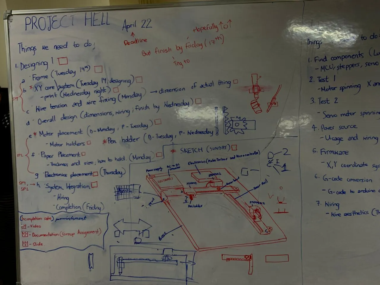
Group Assignment: - Design a machine that includes mechanism + actuation+ automation + function + user interface - Build the mechanical parts and operate it manually - Document the group project!
Individual Assignment: - Document your individual contribution
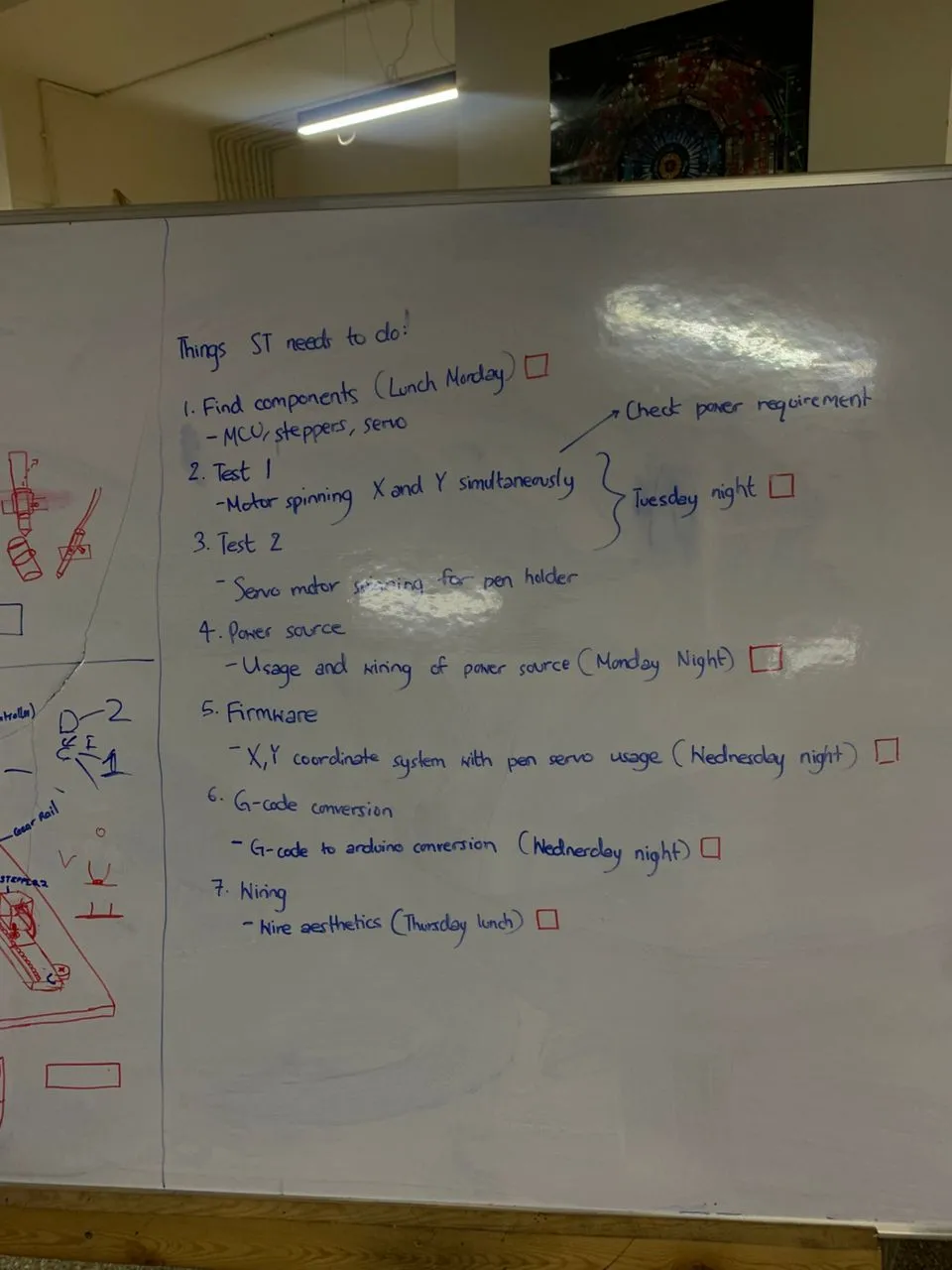
Here is my plan for the week:
What We Built
Here is the link to the Group Assignment: Group Assignment
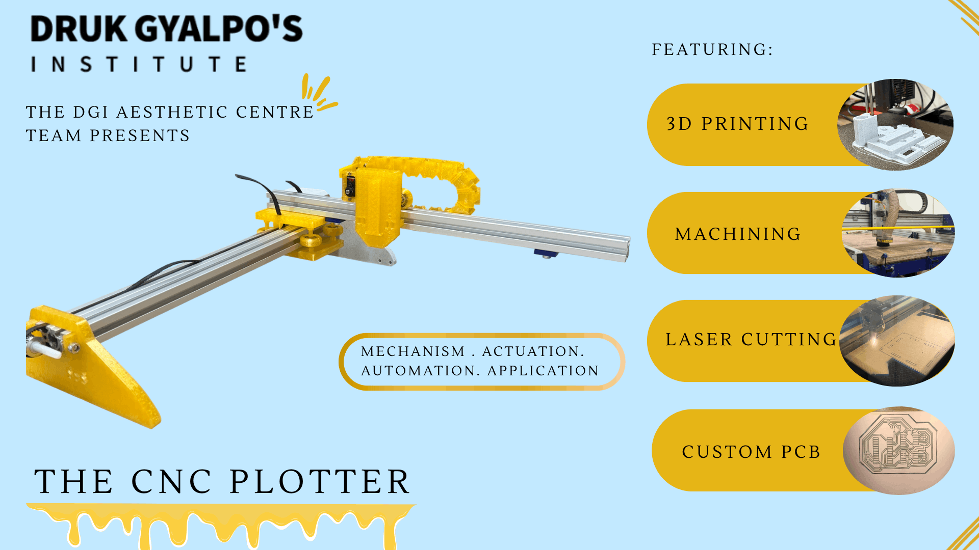
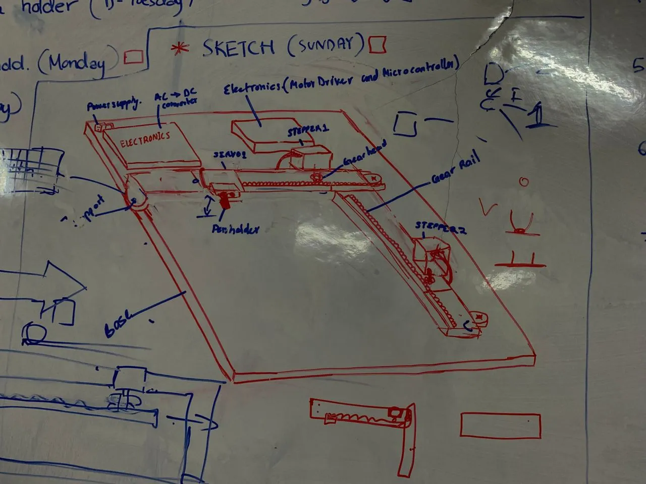
 This week our group of three built a 2-axis pen plotter — a drawing machine that moves a pen across paper using two stepper motors on X and Y axes, controlled by GRBL firmware running on an Arduino Nano. The machine uses GT2 timing belts and 20-tooth pulleys for motion, and an MG90S servo to lift and lower the pen.
We split the work based on what each of us does best. My two teammates handled everything mechanical — the frame design, the CAD work, and the 3D printed pen holder. My part was everything electronics — designing and milling the custom PCB, wiring it all up, testing every component, flashing and configuring GRBL, and getting the whole electronics side talking to the machine.
My Individual Contribution — Electronics
The rest of this page documents my part of the project. For the mechanical side, check out my teammates' pages.
Components
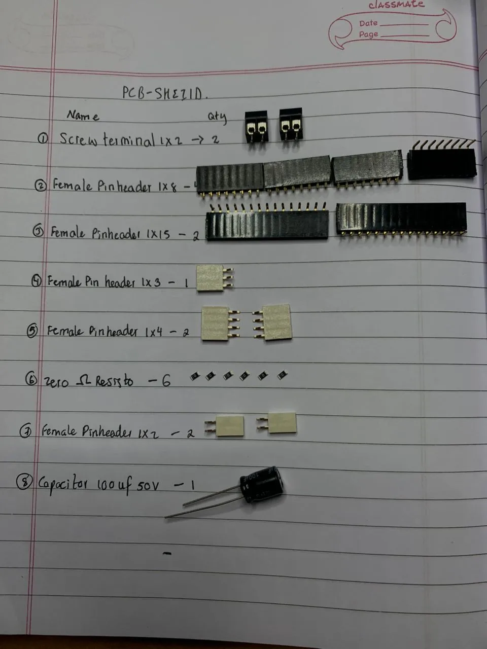
Here's everything that went into the electronics:
| Component | Spec | Quantity |
|---|---|---|
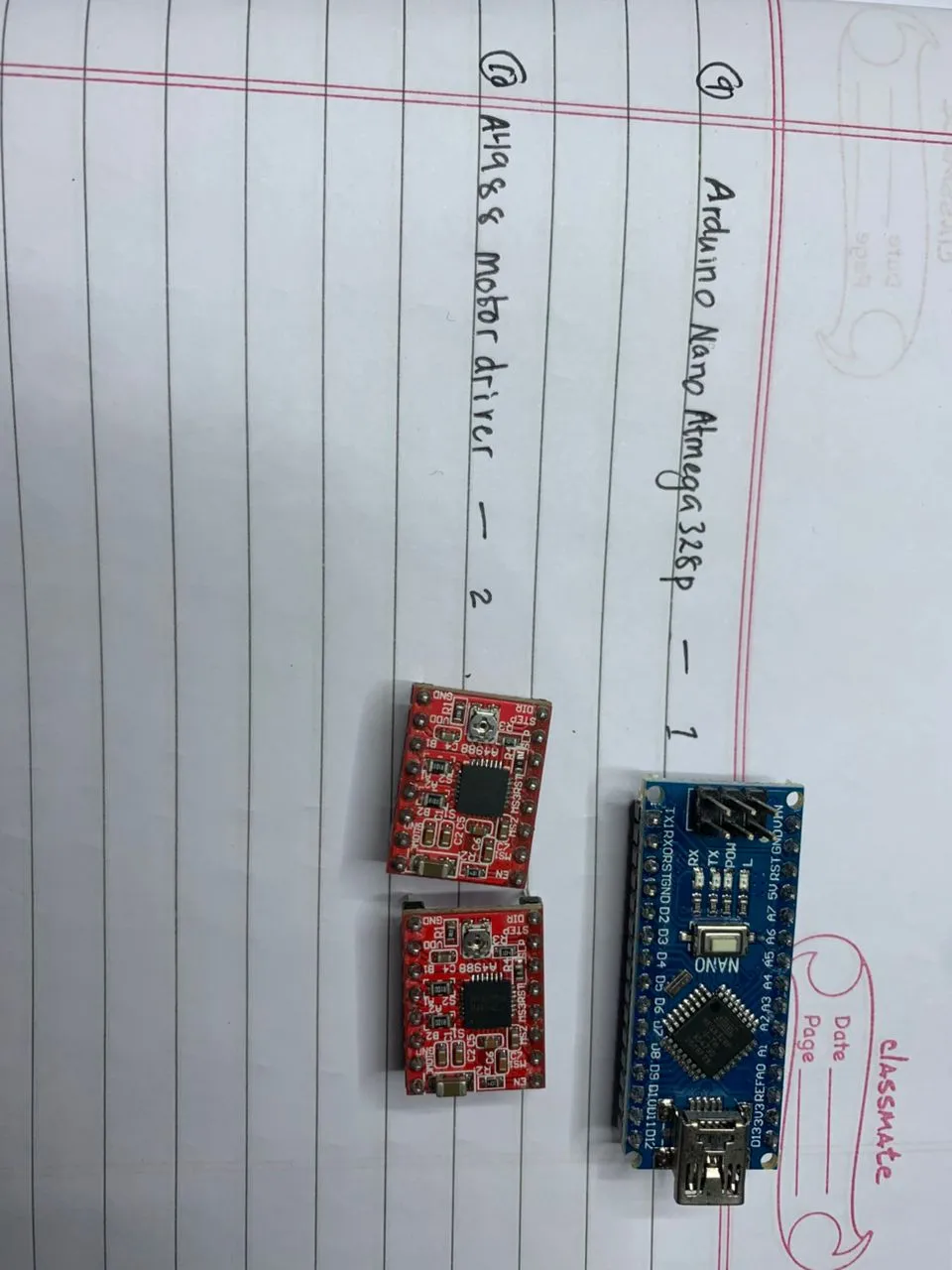
| Arduino Nano | ATmega328P | 1 |
| Stepper Motor | NEMA 17 — Jameco 42BYG44B, 1A, 4V rated | 2 |
| Motor Driver | A4988 module (clone, Rs = 0.1Ω) | 2 |
| Servo | MG90S | 1 |
| Capacitor | 100µF electrolytic | 1 |
| Power Supply (motors) | 12V 5A | 1 |
| Power Supply (logic) | 5V 2.5A | 1 |
PCB Design
I designed a custom PCB in KiCad to keep all the electronics together cleanly instead of running everything off a breadboard. The board handles both stepper motor drivers, the servo signal, and the Arduino Nano, with separate power rails for the motors (12V) and the logic (5V).
Schematic
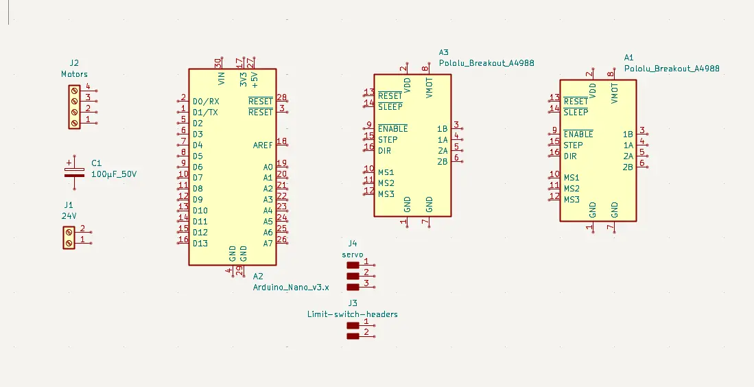
I started by placing all the symbols in KiCad — the Arduino Nano, two A4988 footprints, the servo connector, power connectors, and the 100µF decoupling capacitor on the motor rail.
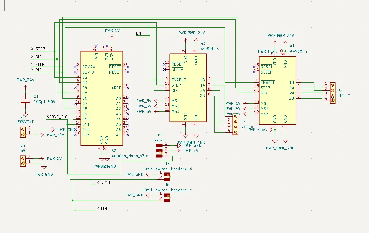
After placing the symbols I wired everything up following the standard GRBL pin mapping:
| Signal | Arduino Nano Pin |
|---|---|
| X STEP | D2 |
| X DIR | D5 |
| Y STEP | D3 |
| Y DIR | D6 |
| EN (Enable) | D8 |
| Servo PWM | D11 |
MS1, MS2, MS3 on both A4988 drivers are hardwired to 5V directly on the board — this locks the drivers into 1/16 microstepping permanently, which gives smooth and quiet movement without needing any firmware configuration for it.
PCB Layout and Routing
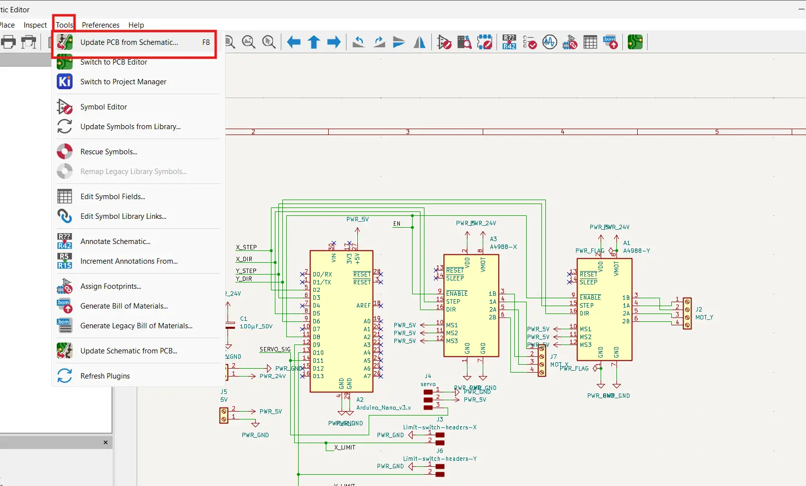
Once the schematic was done I updated the PCB from it and started routing traces.
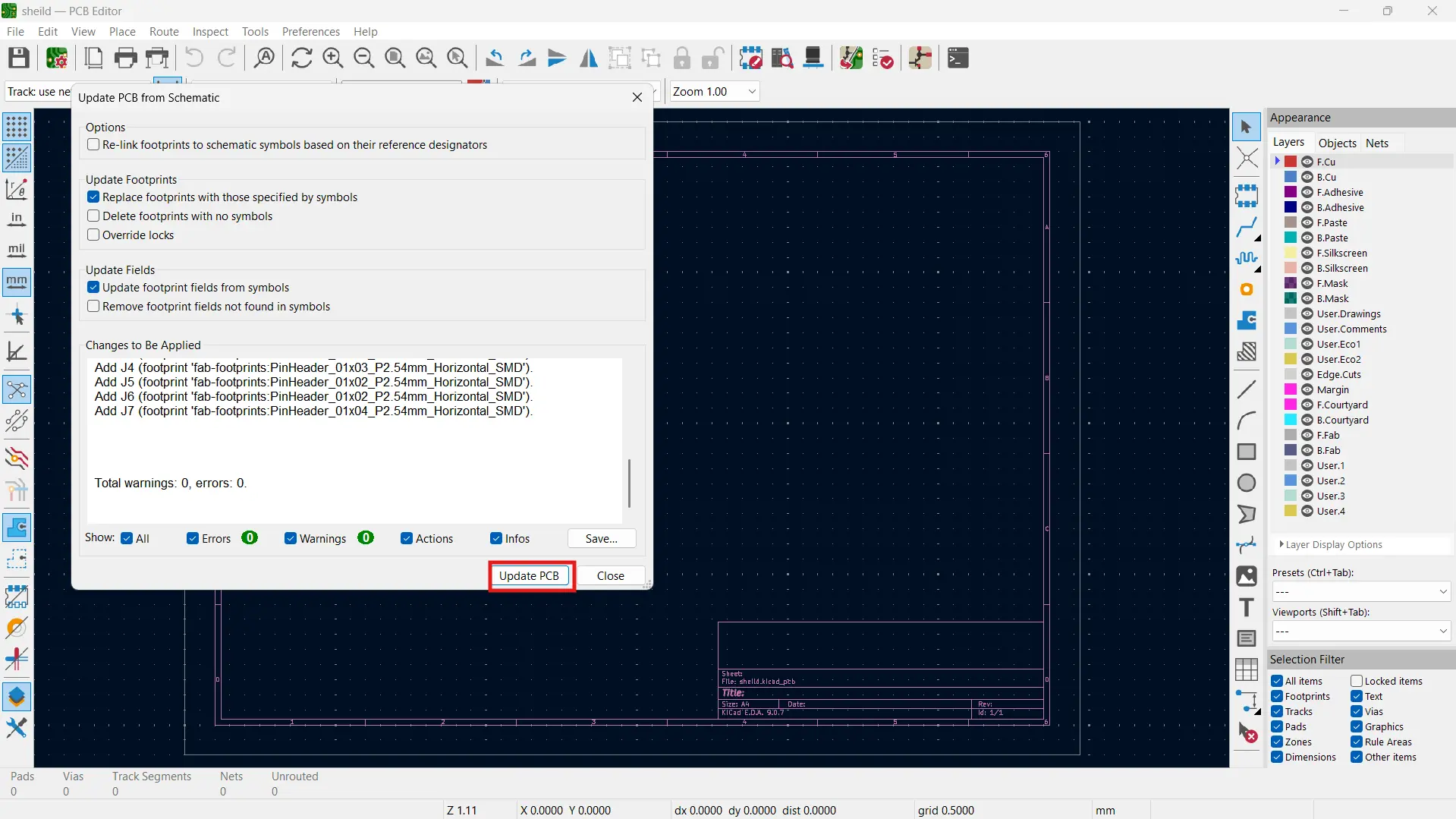
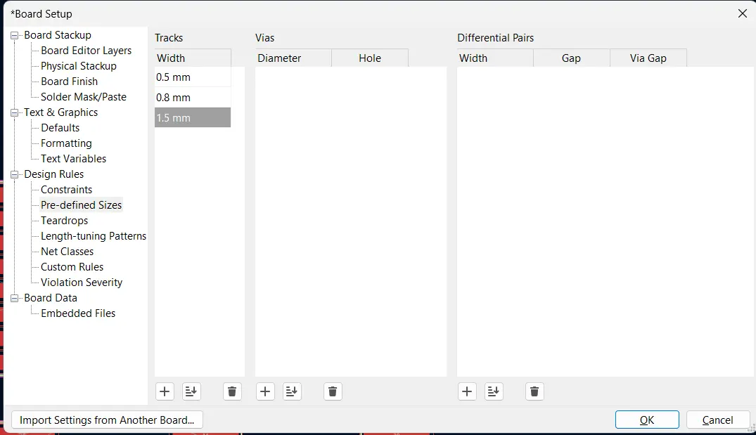
I set the trace width before routing to make sure the power traces were thick enough to handle the current.
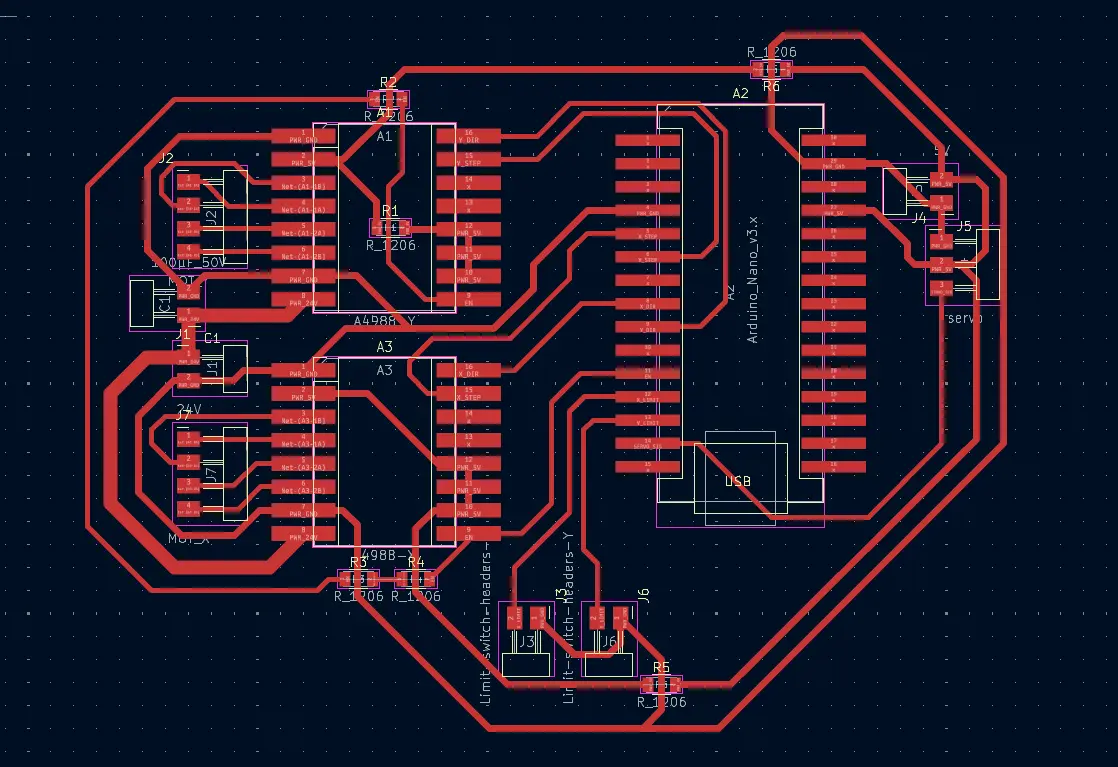
Then I routed all the traces manually.
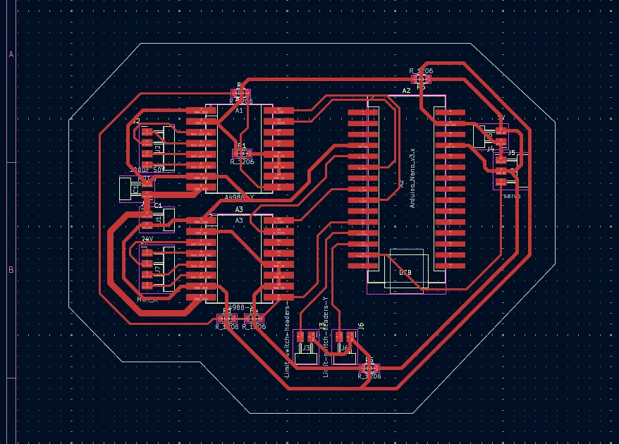
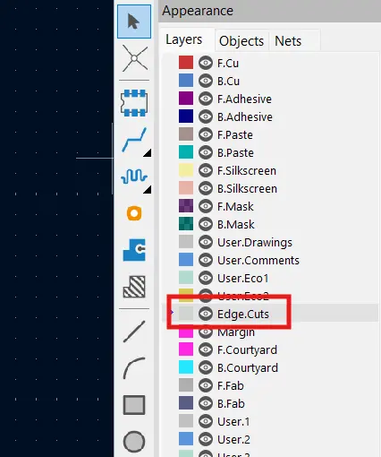
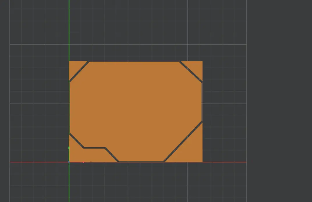
After routing I added the edge cuts to define the board outline.
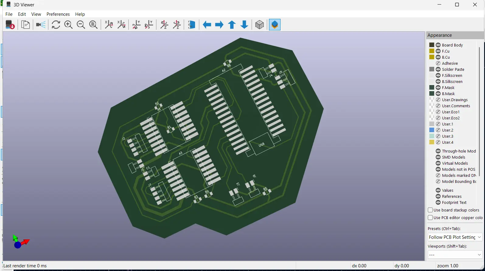
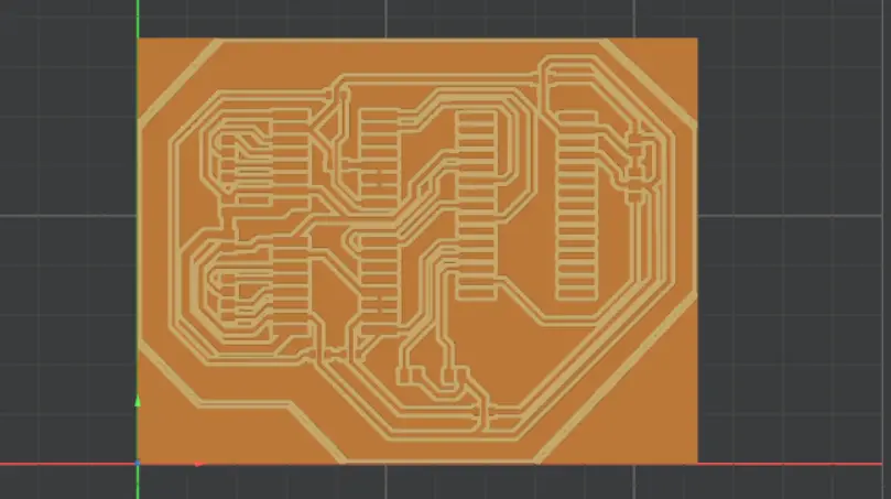
Here's the 3D view of the final board.
Generating the RML File for Milling
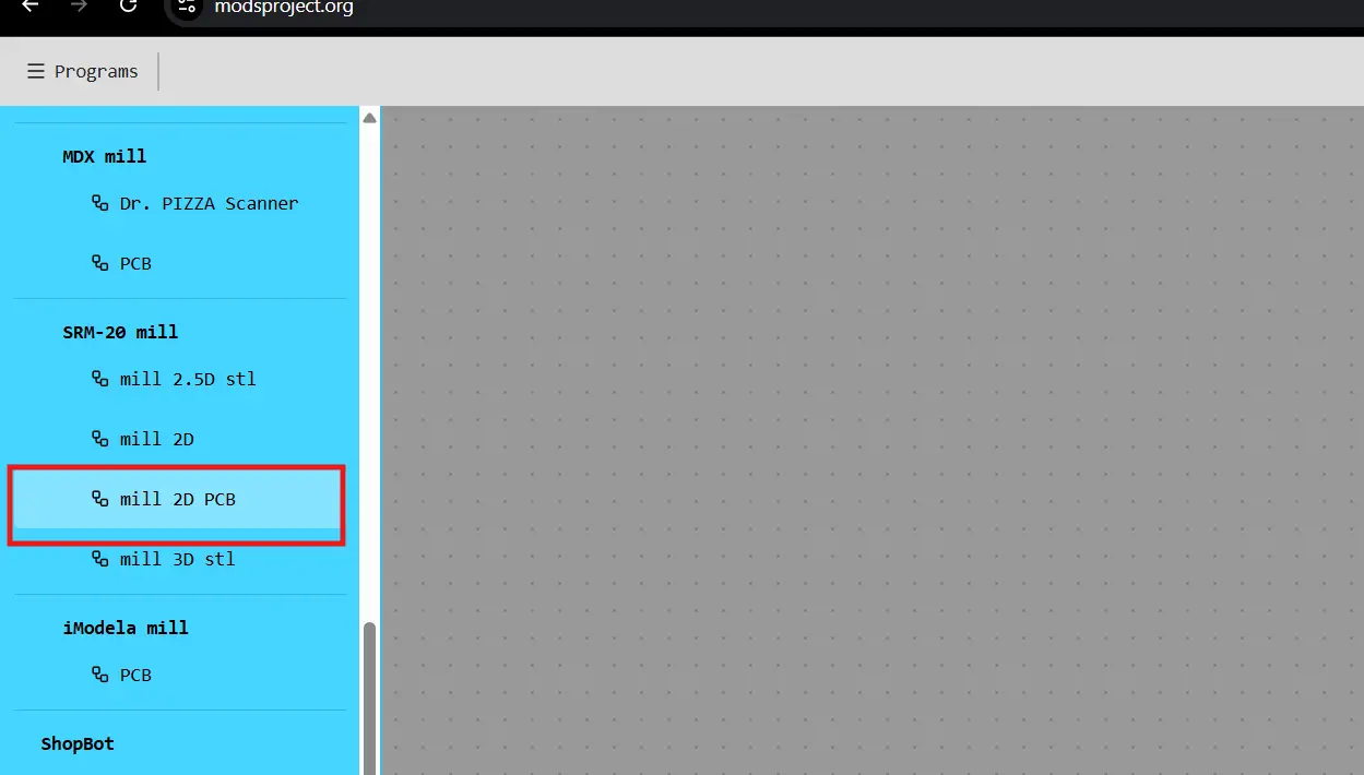
To mill the board I used MODS CE to generate the RML file from the PCB Gerber. The process is the same as Week 8 so I'll keep this brief.
I selected the SRM-20 PCB preset in MODS CE.
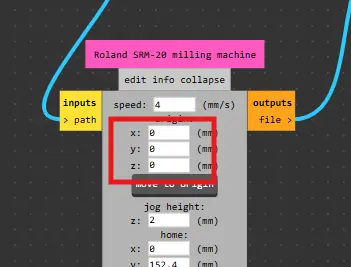
Then I set the origin to zero.
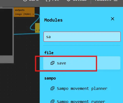
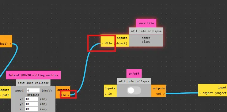
I added the save module to export the RML file.
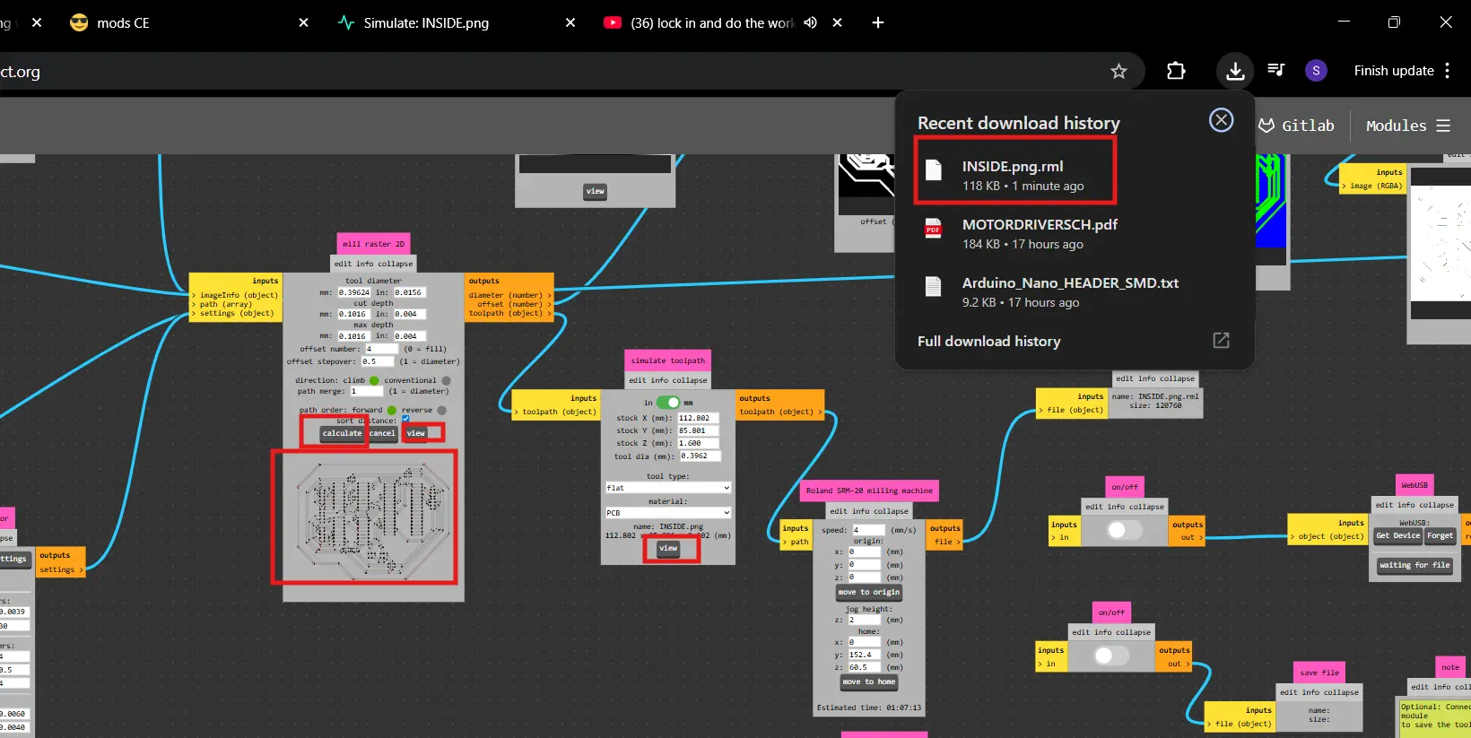
I calculated and downloaded the RML file.
I also generated a separate RML file for the edge cuts.
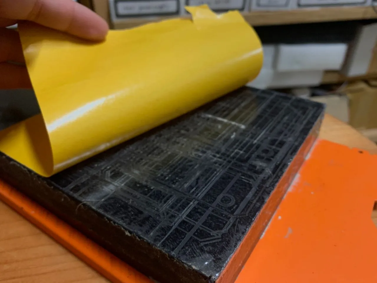
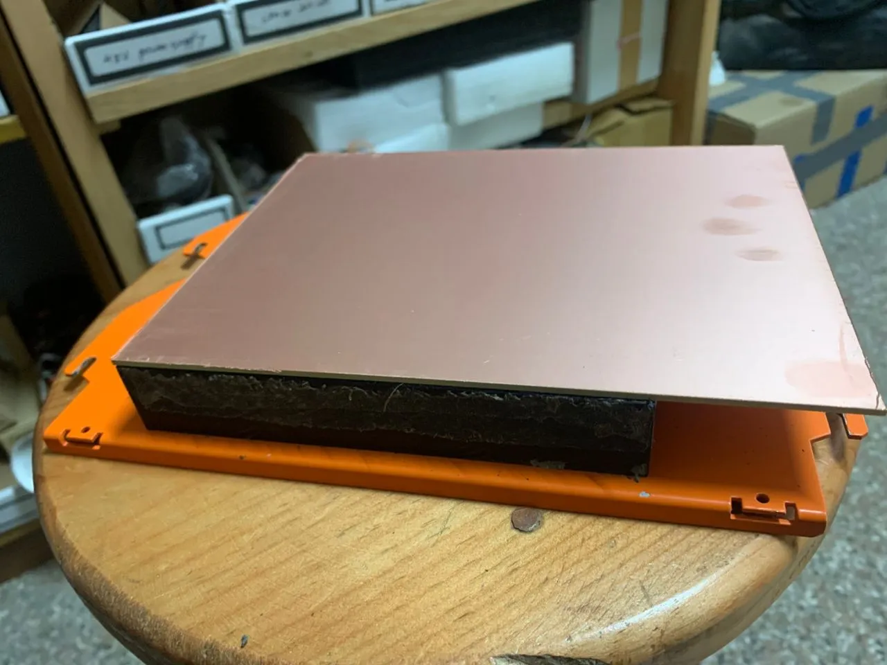
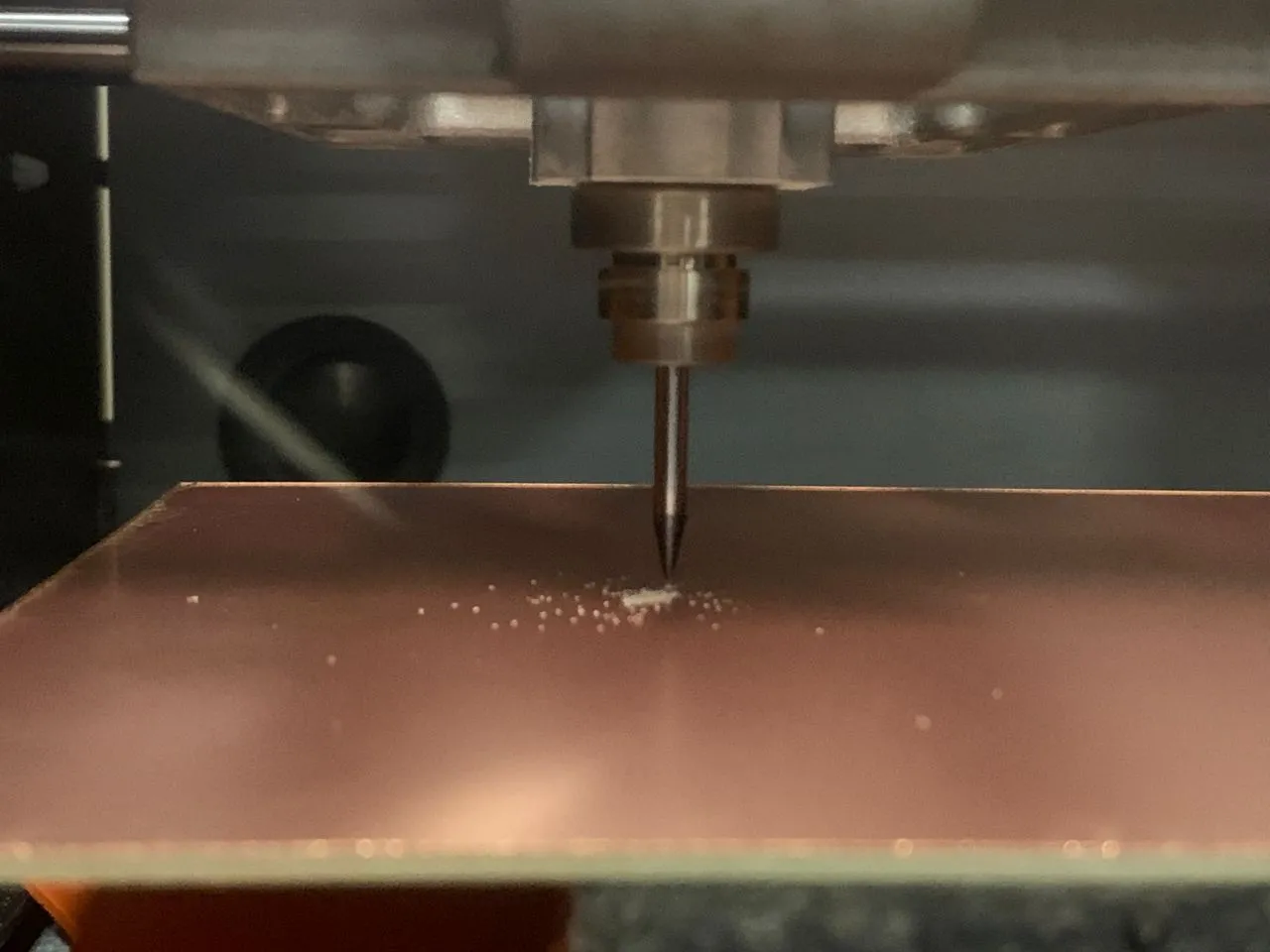
Milling the PCB
I used the Roland SRM-20 — same machine as Week 8. First I stuck the copper plate to the sacrificial board with double-sided adhesive tape.
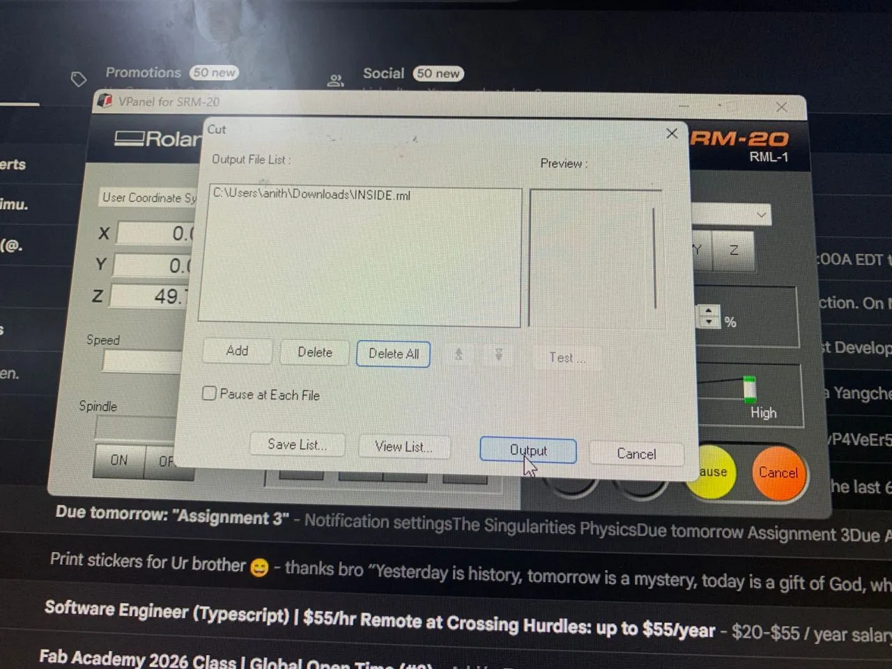
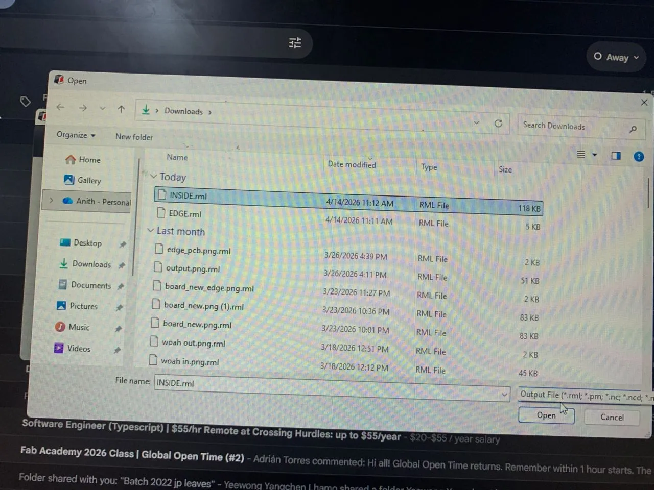
Then I sent the RML file to the machine from the desktop software.
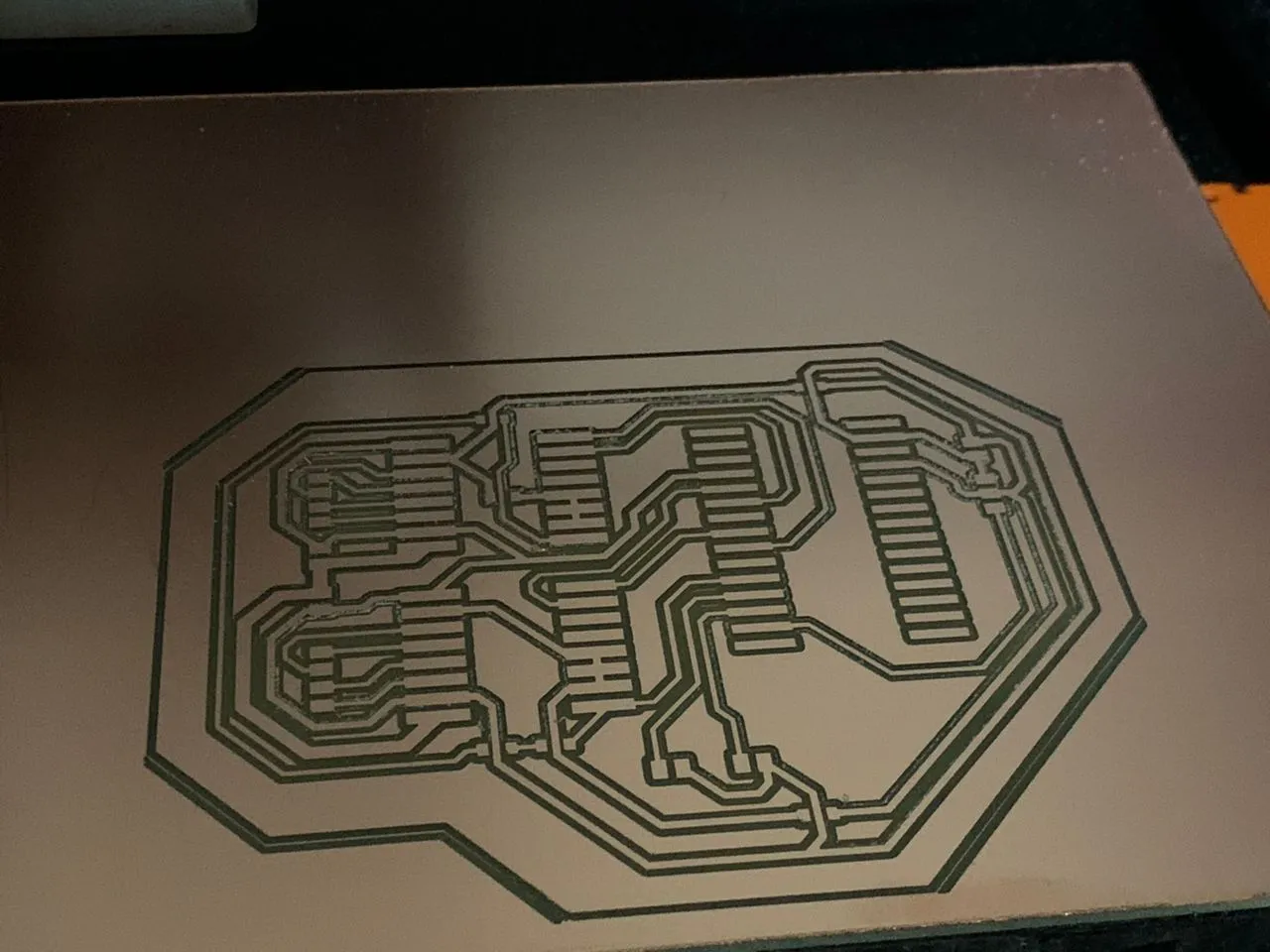
The trace milling went cleanly.
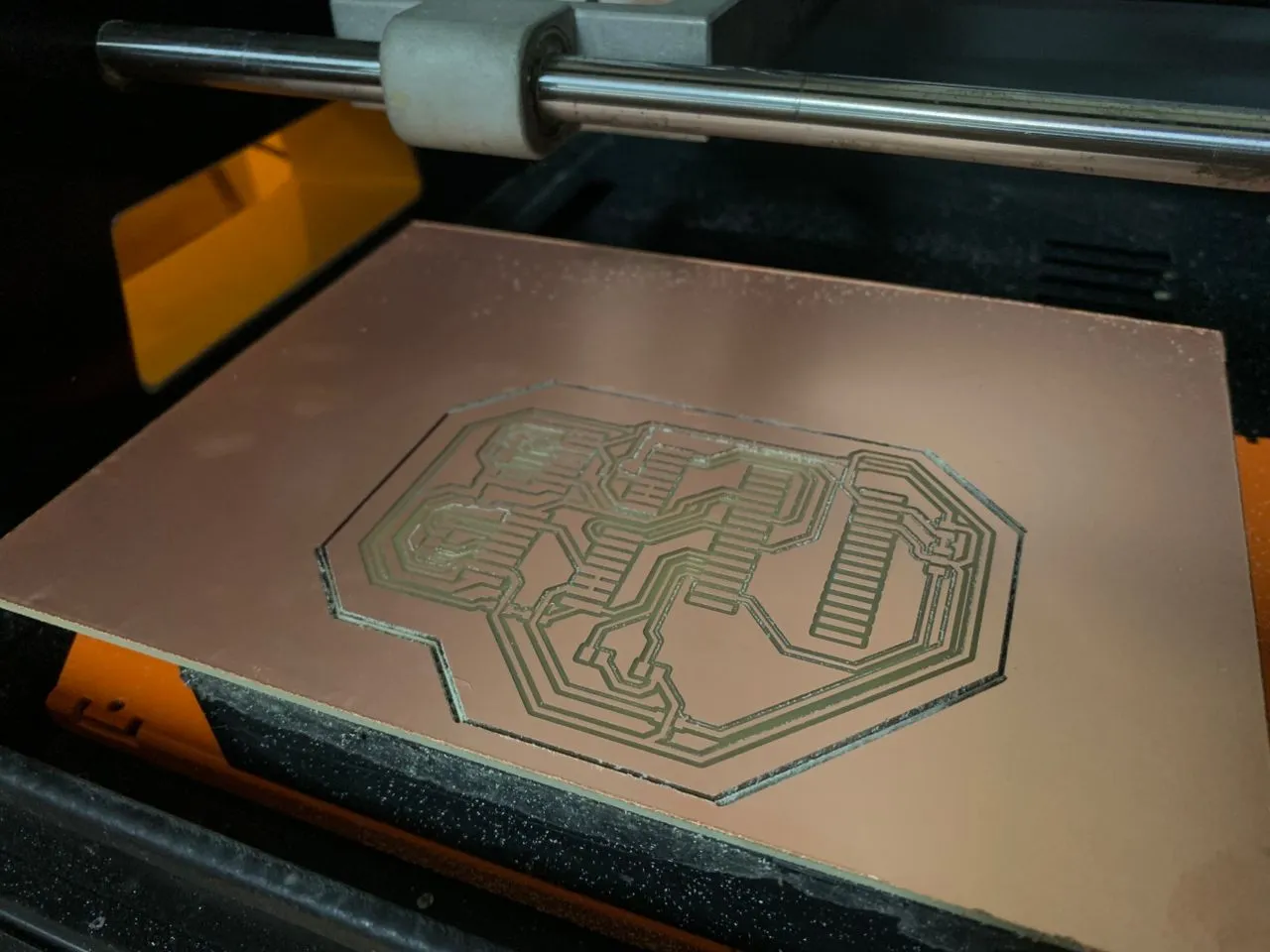
Then I ran the edge cut.
Soldering
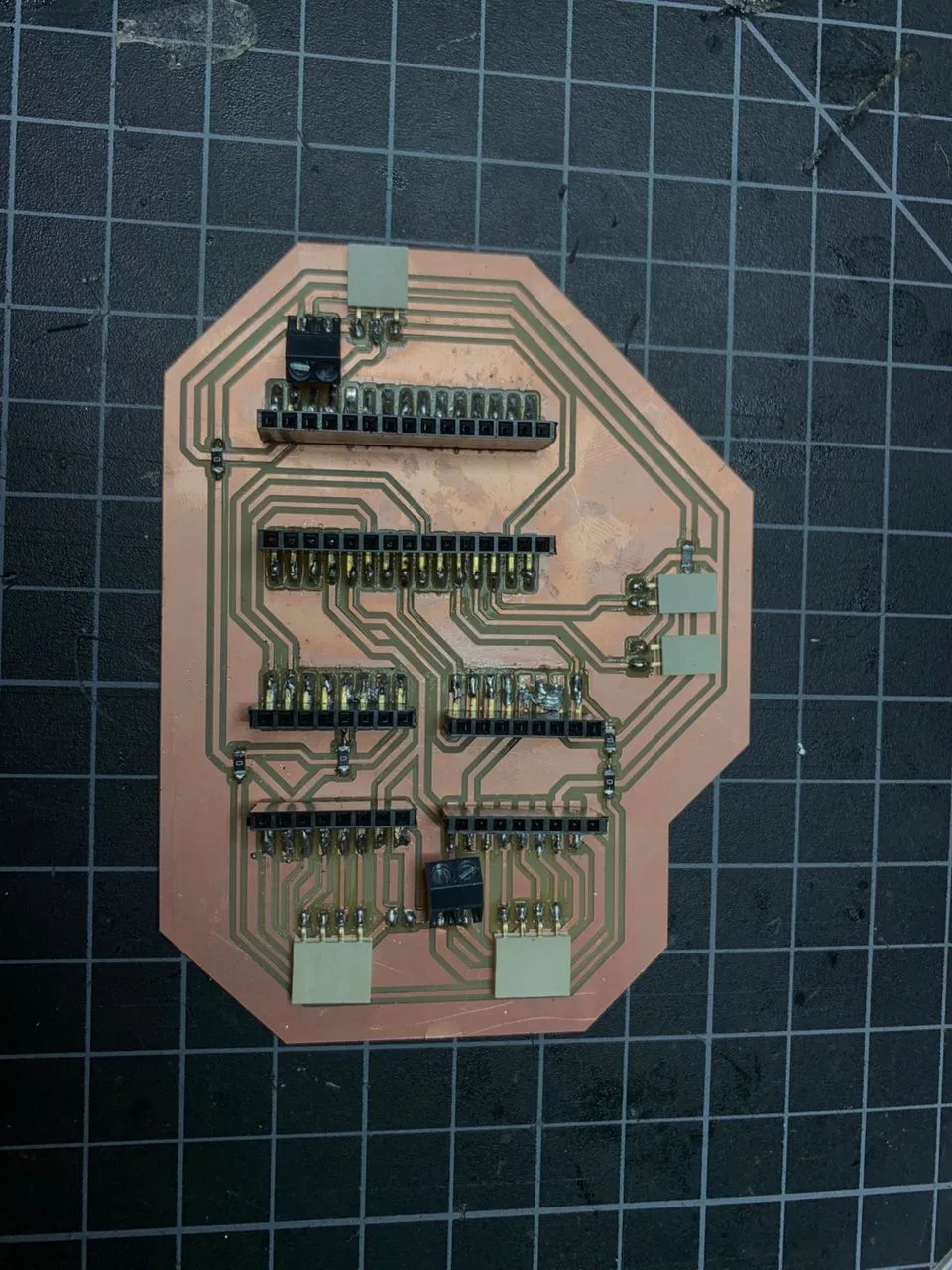
After milling I soldered all the components onto the board.
Here's the finished soldered board.
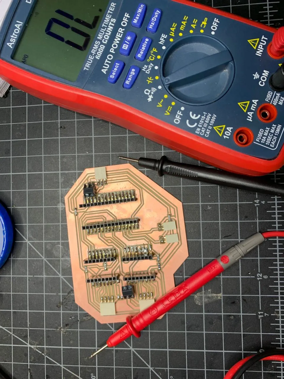
Testing the PCB Connections
Before powering anything I checked all the traces with a multimeter in continuity mode to make sure nothing was shorted or broken. Everything beeped correctly — all traces continuous, no shorts between power rails.
Setting the Vref
Before connecting any motors I had to set the Vref on both A4988 drivers. This controls the current limit the driver sends to the motor — getting it wrong can burn out the motors or the drivers.
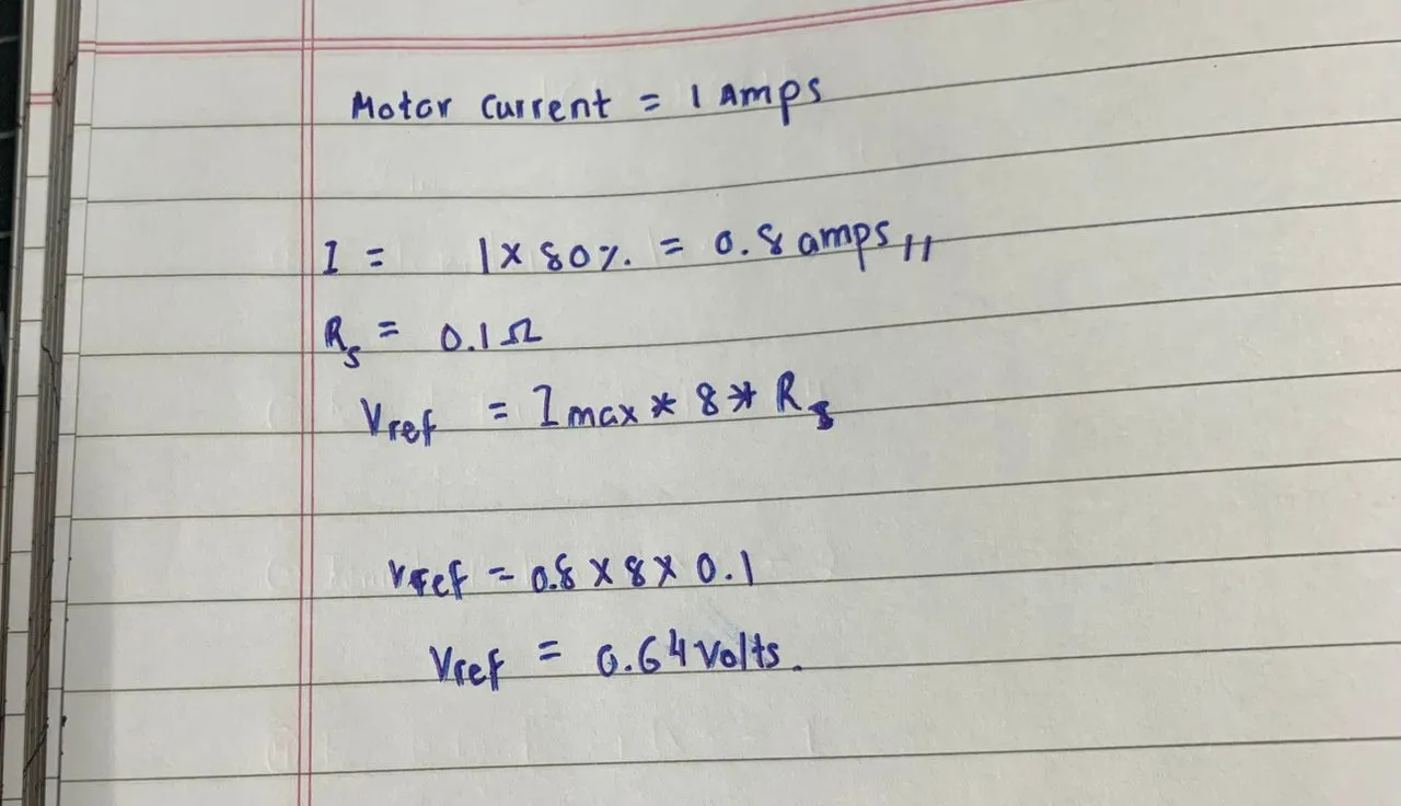
The formula is:
Vref = Imotor × 8 × Rs
My motors are rated at 1A and the A4988 modules have 0.1Ω sense resistors (marked R100 on the chip). I run the motors at 80% of rated current to keep them cool, so:
Vref = 0.8A × 8 × 0.1Ω = 0.64V
I worked out the calculation on paper first before touching the trimmer pot.
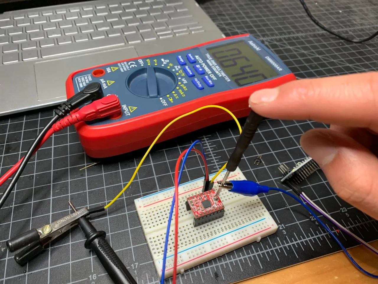
Then I set up the A4988 on the breadboard with 12V and the Nano connected, and measured Vref at the trimmer pot center with the multimeter. Red probe on the trimmer, black probe to GND. I adjusted slowly until both drivers read exactly 0.64V.
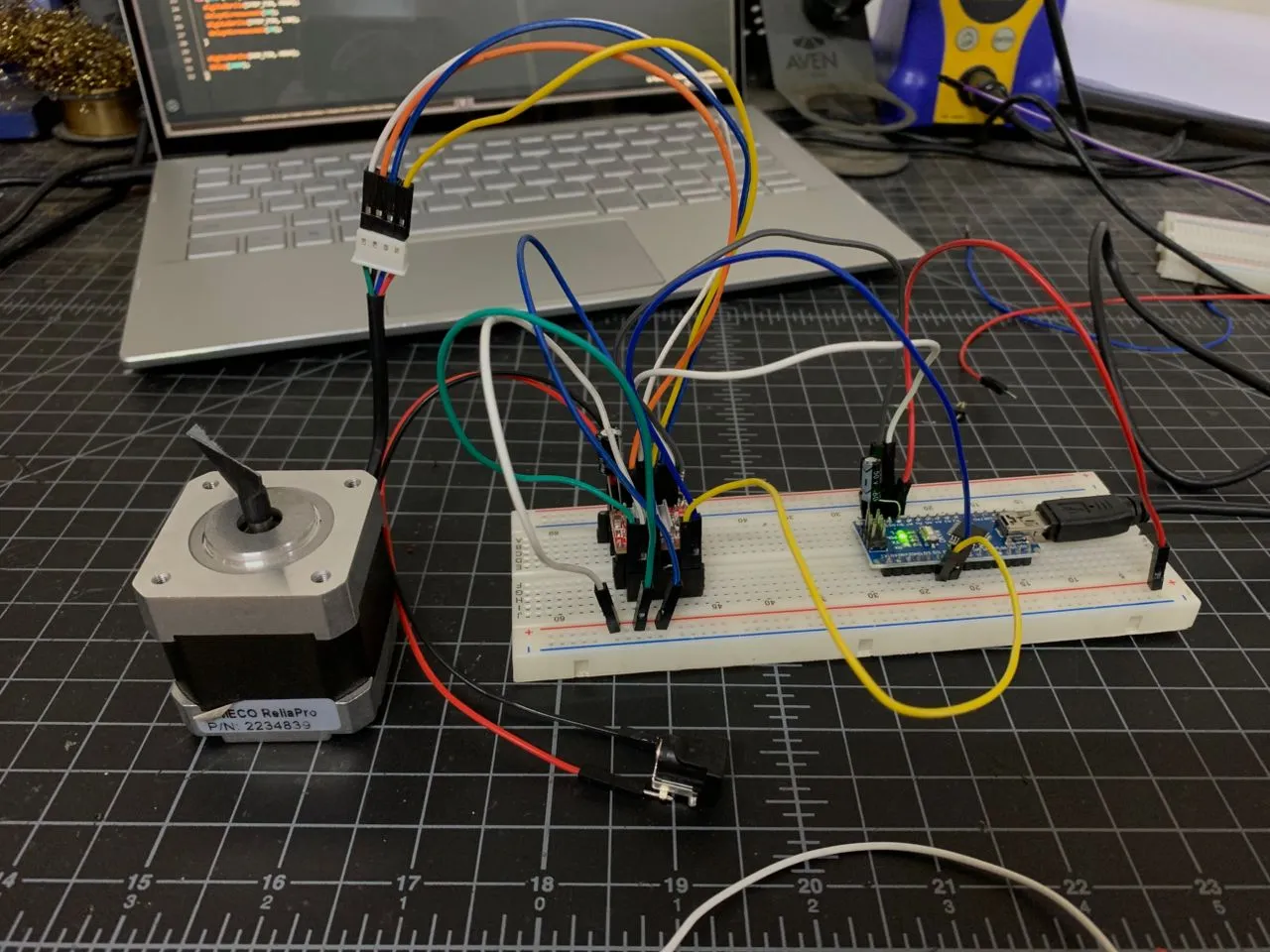
Breadboard Motor Test
Before trusting the PCB I tested everything on a breadboard first — one A4988, one motor, the Nano. Good habit — verify the components work before combining them.
I wired up the full A4988 circuit: VMOT to 12V, VDD to Nano 5V, common GND between Nano and driver, SLEEP and RESET tied together, MS1/2/3 all to 5V for 1/16 microstepping, and the motor wires in the correct coil order (Red→1A, Blue→1B, Green→2A, Black→2B).
The first few tests didn't spin — the motor was just vibrating. Turned out it was a combination of the step delay being too fast and the EN pin not being pulled LOW in the code. Once I fixed both of those and confirmed the SLEEP/RESET tie the motor started spinning cleanly.
I ran through a series of delay values to find the speed limits:
| delayMicroseconds | Mode | Status |
|---|---|---|
| 2000µs | Full step | ✅ Smooth |
| 500µs | Full step | ✅ Smooth |
| 300µs | Full step | ❌ Not turning |
| 500µs | 1/16 micro | ✅ Smooth |
| 200µs | 1/16 micro | ✅ Working |
| 50µs | 1/16 micro | ✅ Smoothest |
| 30µs | 1/16 micro | ✅ Working |
| 20µs | 1/16 micro | ❌ Not spinning |
The 1/16 microstepping was noticeably smoother and quieter than full step — the steps blend together almost like a sine wave at high step rates. The sweet spot ended up being around 50µs: smooth, quiet, and reliable. I confirmed both motors worked the same way before moving to the PCB.
Testing on the Custom PCB
With breadboard testing done I moved to the custom PCB. The pin mapping follows the GRBL standard so I had to make sure my code matched:
#define STEP_PIN 2   // X STEP → D2
#define DIR_PIN 5    // X DIR → D5
#define EN_PIN 8     // EN → D8

void setup() {
  pinMode(STEP_PIN, OUTPUT);
  pinMode(DIR_PIN, OUTPUT);
  pinMode(EN_PIN, OUTPUT);
  digitalWrite(EN_PIN, LOW);  // LOW = driver enabled
  digitalWrite(DIR_PIN, HIGH);
}

void loop() {
  for(int i = 0; i < 3200; i++) {
    digitalWrite(STEP_PIN, HIGH);
    delayMicroseconds(50);
    digitalWrite(STEP_PIN, LOW);
    delayMicroseconds(50);
  }
  delay(1000);
  digitalWrite(DIR_PIN, LOW);
  for(int i = 0; i < 3200; i++) {
    digitalWrite(STEP_PIN, HIGH);
    delayMicroseconds(50);
    digitalWrite(STEP_PIN, LOW);
    delayMicroseconds(50);
  }
  digitalWrite(DIR_PIN, HIGH);
  delay(1000);
}
One thing I had to figure out — on the PCB the EN pin goes to D8, which is how GRBL controls it. But since I was running a simple test sketch GRBL wasn't managing it, so D8 was floating. I had to explicitly set digitalWrite(EN_PIN, LOW) to enable the drivers. Without that line the motor does absolutely nothing.
I also added short jumper wires bridging SLEEP and RESET directly on each A4988 module — GRBL handles this automatically later but for manual sketch testing the sketch wasn't controlling those pins so they needed to be tied.
Motor X working:
Then I tested Motor Y (D3/D6), both motors together in the same direction, both in opposite directions, and finally independent control — X spinning while Y stays still, then Y while X stays still.
Each test passed cleanly:
| Test | Status |
|---|---|
| Motor X individual (D2/D5) | ✅ |
| Motor Y individual (D3/D6) | ✅ |
| Both motors same direction | ✅ |
| Both motors opposite direction | ✅ |
| Independent motor control | ✅ |
Servo Test
With motors confirmed I moved to the servo. The MG90S connects to D11 (signal), 5V, and GND on the PCB. I uploaded a simple angle finder sketch that takes inputs over Serial Monitor and moves the servo to them, cycling UP and DOWN three times so you can check the position visually:
#include <Servo.h>

Servo penServo;
int penUp = -1;
int penDown = -1;

void setup() {
  Serial.begin(9600);
  penServo.attach(11);
  Serial.println("=== Pen Servo Angle Finder ===");
  Serial.print("Enter PEN UP angle (0-180): ");
}

void loop() {
  if (Serial.available() > 0) {
    String input = Serial.readStringUntil('\n');
    input.trim();
    int angle = input.toInt();

    if (penUp == -1) {
      penUp = angle;
      penServo.write(penUp);
      Serial.print("PEN UP set to: ");
      Serial.println(penUp);
      delay(1500);
      Serial.print("Enter PEN DOWN angle: ");
    } else if (penDown == -1) {
      penDown = angle;
      penServo.write(penDown);
      Serial.print("PEN DOWN set to: ");
      Serial.println(penDown);
      delay(1500);
      Serial.println("Cycling 3 times...");
      for (int i = 0; i < 3; i++) {
        penServo.write(penUp);
        Serial.println("PEN UP");
        delay(1500);
        penServo.write(penDown);
        Serial.println("PEN DOWN");
        delay(1500);
      }
      penUp = -1;
      penDown = -1;
    }
  }
}
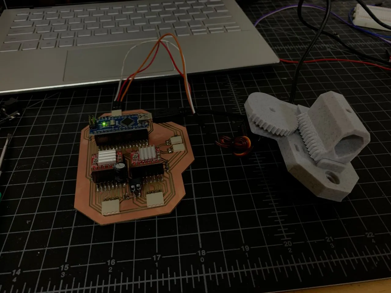
My teammate had finished the first version of the 3D printed pen holder at this point so I could test with the actual assembly. After trying a few angles:
| Position | Angle |
|---|---|
| Pen UP | 90° |
| Pen DOWN | 0° |
All Components Together
Before moving to firmware I ran one final test with all three components running simultaneously — both stepper motors and the servo — to make sure there were no interference issues between them.
#include <Servo.h>

#define STEP_X 2
#define DIR_X 5
#define STEP_Y 3
#define DIR_Y 6
#define EN_PIN 8
#define SERVO_PIN 11

Servo penServo;

void setup() {
  pinMode(STEP_X, OUTPUT); pinMode(DIR_X, OUTPUT);
  pinMode(STEP_Y, OUTPUT); pinMode(DIR_Y, OUTPUT);
  pinMode(EN_PIN, OUTPUT);
  digitalWrite(EN_PIN, LOW);
  digitalWrite(DIR_X, HIGH); digitalWrite(DIR_Y, HIGH);
  penServo.attach(SERVO_PIN);
}

void loop() {
  penServo.write(90); // Pen UP
  delay(1000);
  for(int i = 0; i < 3200; i++) {
    digitalWrite(STEP_X, HIGH); digitalWrite(STEP_Y, HIGH);
    delayMicroseconds(50);
    digitalWrite(STEP_X, LOW); digitalWrite(STEP_Y, LOW);
    delayMicroseconds(50);
  }
  delay(500);
  penServo.write(0); // Pen DOWN
  delay(1000);
  for(int i = 0; i < 3200; i++) {
    digitalWrite(STEP_X, HIGH); digitalWrite(STEP_Y, HIGH);
    delayMicroseconds(50);
    digitalWrite(STEP_X, LOW); digitalWrite(STEP_Y, LOW);
    delayMicroseconds(50);
  }
  delay(500);
}
Everything worked together cleanly — no jitter, no interference between the servo PWM and the stepper signals. Hardware fully verified. ✅
Flashing GRBL
With all the hardware confirmed working it was time to flash GRBL firmware. I used grbl-servo — a fork of GRBL specifically made for pen plotters that controls the servo through the spindle PWM pin (D11) using M3/M5 commands. The PWM frequency is set to 61Hz which is perfect for the MG90S.
Downloading and Installing
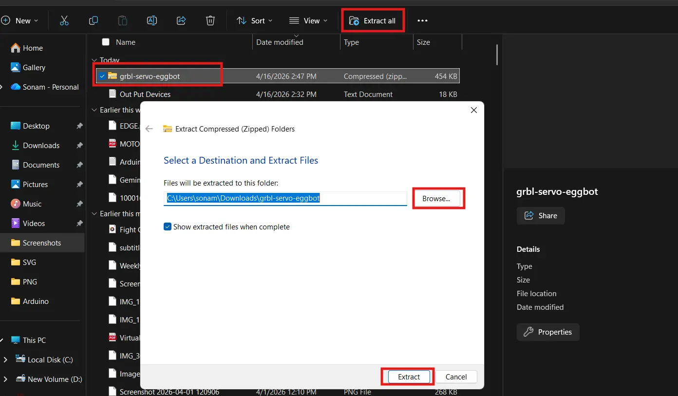
I downloaded the grbl-servo ZIP from the cprezzi/grbl-servo GitHub repository.
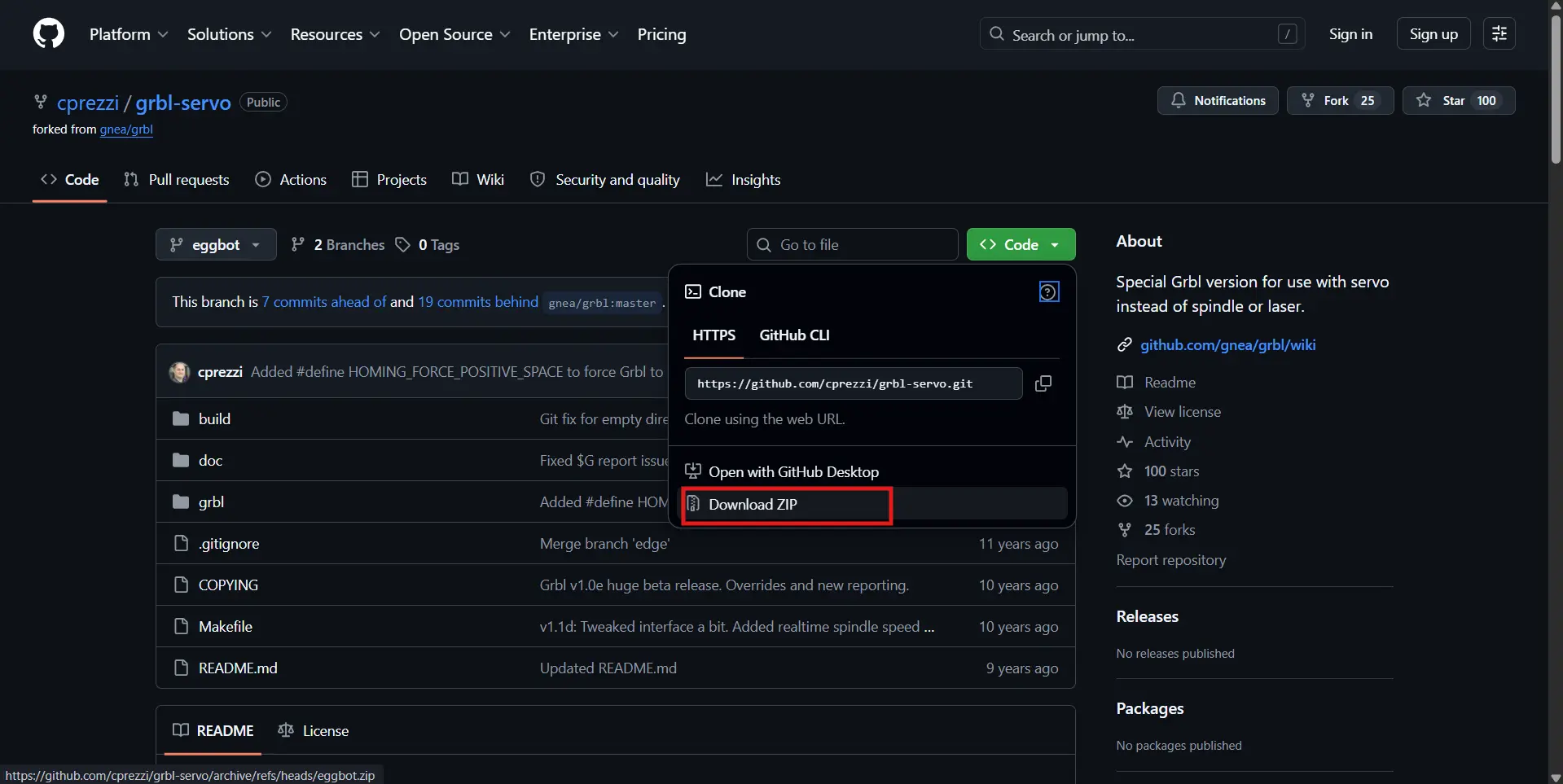
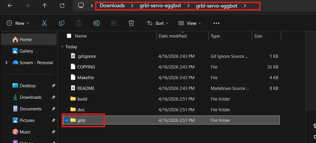
Extracted the ZIP and found the inner grbl folder.
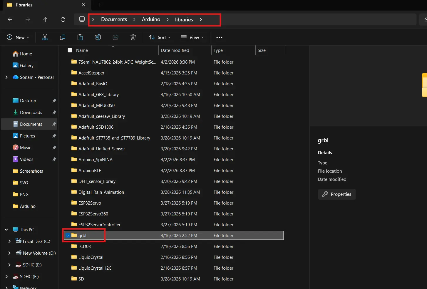
Then copied just that inner grbl folder into Documents → Arduino → libraries.
Uploading
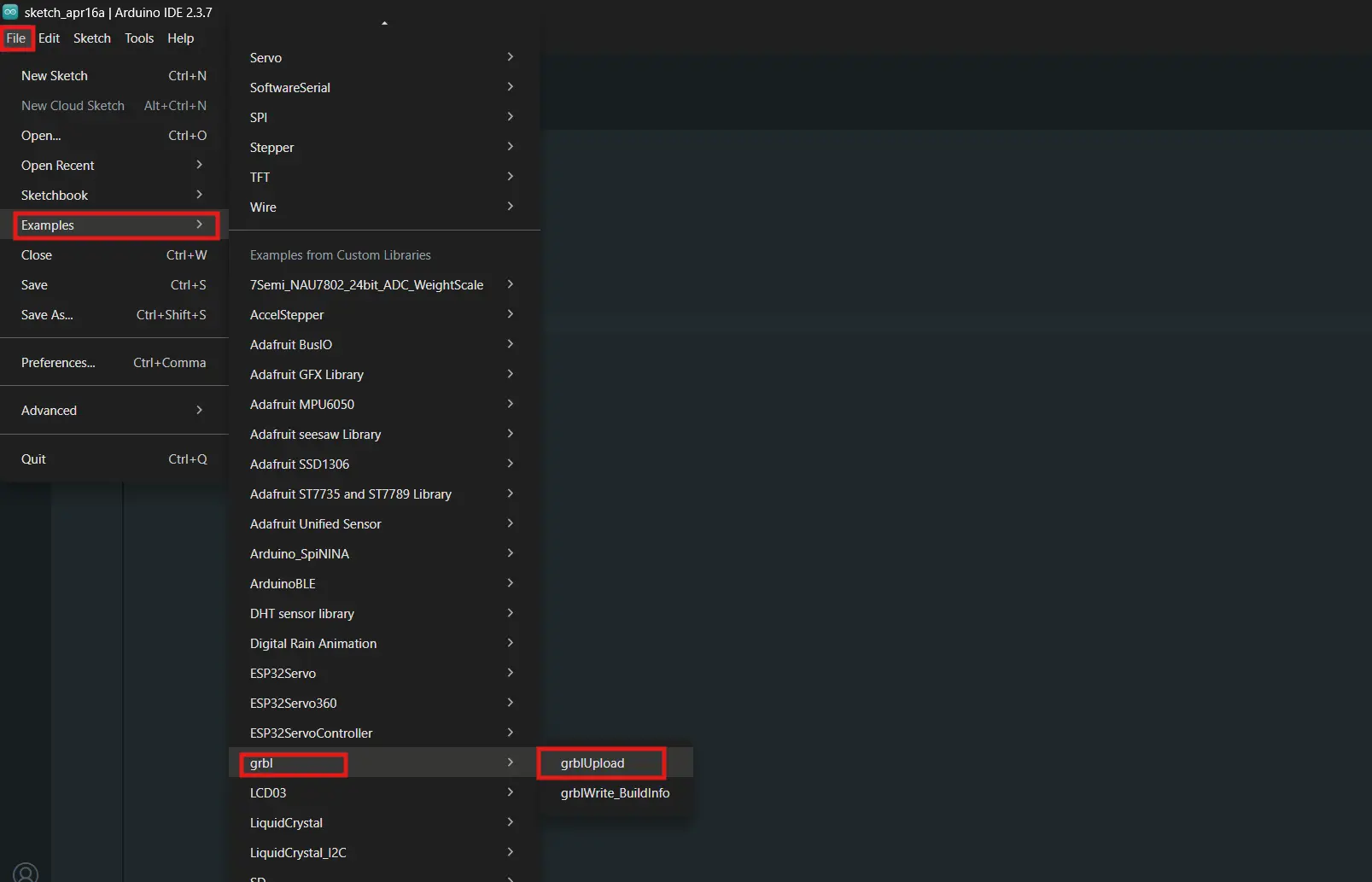
I opened File → Examples → grbl → grblUpload and uploaded it to the Nano.
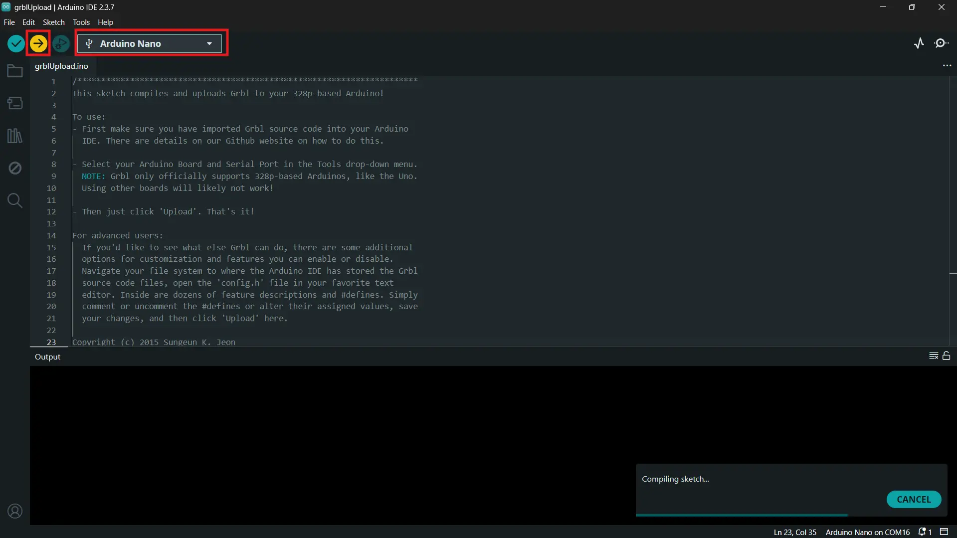
GRBL uses 97% of the Nano's flash — that's completely expected. It's a big firmware that's heavily optimized to fit on the ATmega328P. Upload completed successfully.
Problem — Nano Bootloader Issue
After flashing GRBL and doing some initial testing, the Nano suddenly stopped responding to uploads. TX/RX LEDs weren't blinking on plug-in, and every upload attempt came back with:
The Nano was getting power but the bootloader wasn't responding at all. I went through the full diagnosis:
- Power LED was on ✅
- COM port visible in Device Manager ✅
- Tried both
ATmega328PandATmega328P (Old Bootloader)processor settings ❌ - Tried different baud rates ❌
- Tried the manual reset timing trick during upload ❌
After some digging the real fix turned out to be a CH340 driver version issue. The latest CH340 driver on Windows has a known incompatibility with certain clone Nanos. The fix was to install an older version — specifically version 3.7.2022.01 — from the archived WCH page.
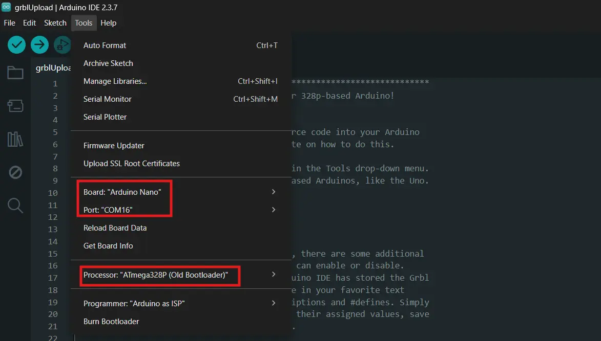
I also had to switch the processor setting to ATmega328P (Old Bootloader) to match the bootloader on the clone boards.
With those two fixes applied to a second Nano from the lab, uploads started working immediately.
| Setting | Value |
|---|---|
| Board | Arduino Nano |
| Processor | ATmega328P (Old Bootloader) |
| CH340 driver | Version 3.7.2022.01 |
| Port | COM17 |
| Baud (upload) | 57600 |
I reflashed GRBL on the new Nano and verified it in Serial Monitor at 115200 baud.
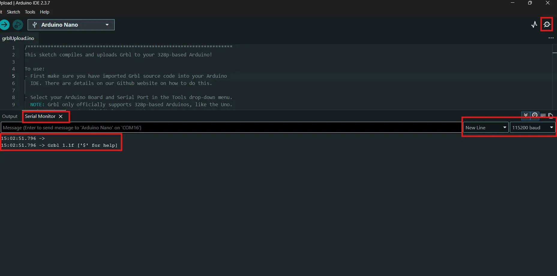
Grbl 1.1f ['$' for help] — we're back. ✅
The lesson: if you're using clone Nanos on Windows and getting not in sync errors, try the older CH340 driver before assuming the board is dead.
Configuring GRBL
With GRBL running on the new Nano I configured all the settings. The most important one is steps/mm — this tells GRBL how many motor steps equal one millimeter of travel.
Steps/mm calculation:
- 1/16 microstepping → 3200 steps per revolution
- GT2 belt → 2mm pitch
- 20 tooth pulley
I sent these commands one by one in Serial Monitor, each returning ok:
$100=80    → X steps/mm
$101=80    → Y steps/mm
$110=3000  → X max speed (mm/min)
$111=3000  → Y max speed (mm/min)
$120=500   → X acceleration (mm/s²)
$121=500   → Y acceleration (mm/s²)
$30=255    → Servo max S value
$31=0      → Servo min S value
$32=0      → Laser mode OFF
I verified with $$ to confirm everything saved correctly.
Testing with UGS
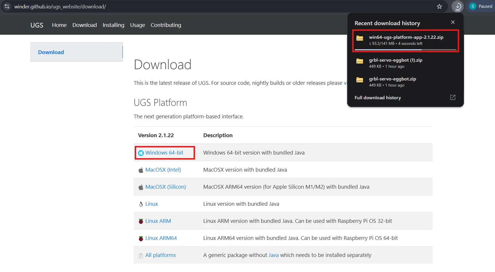
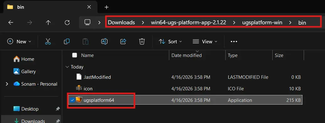
To verify GRBL was actually controlling the motors I installed Universal G-code Sender (UGS Platform).
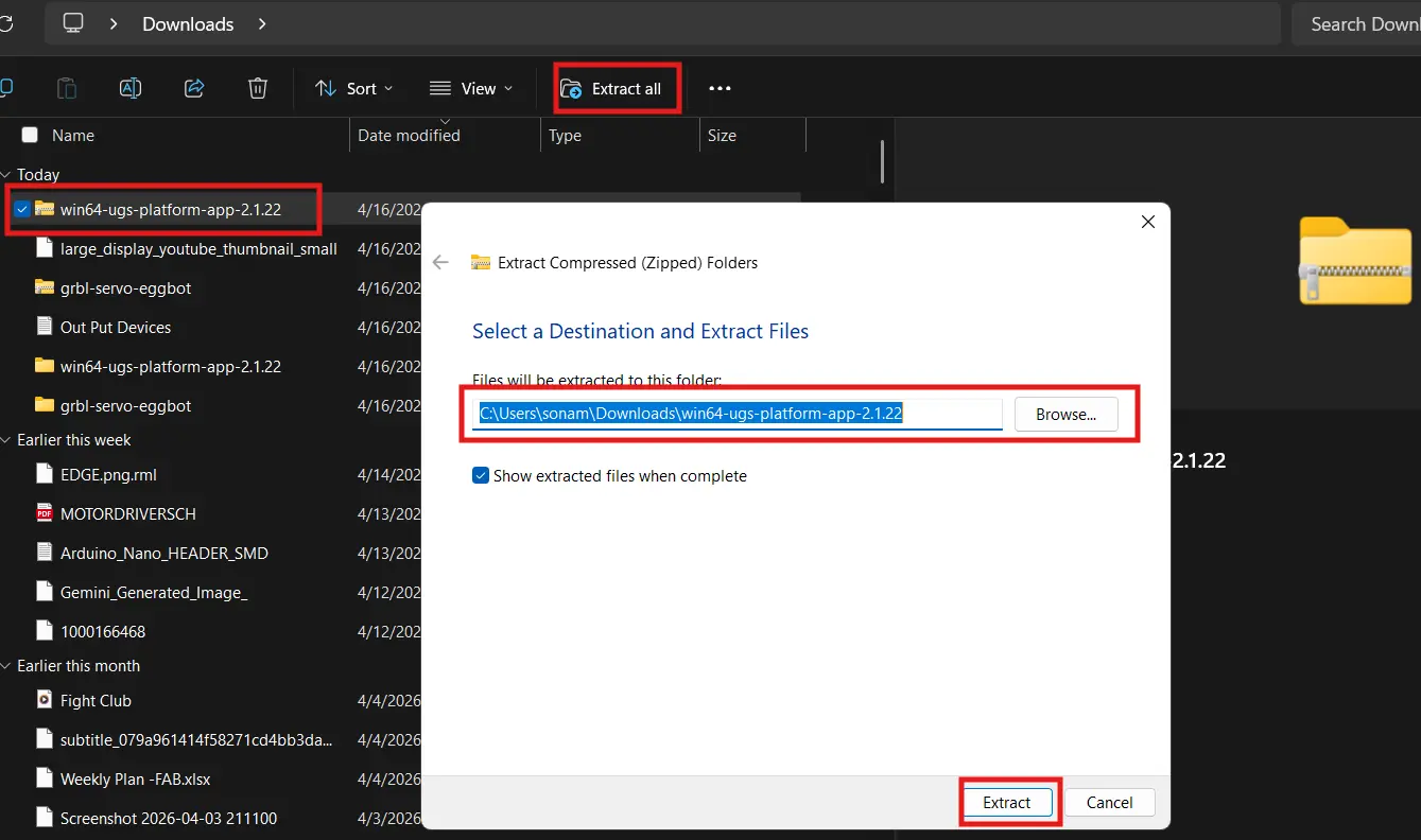
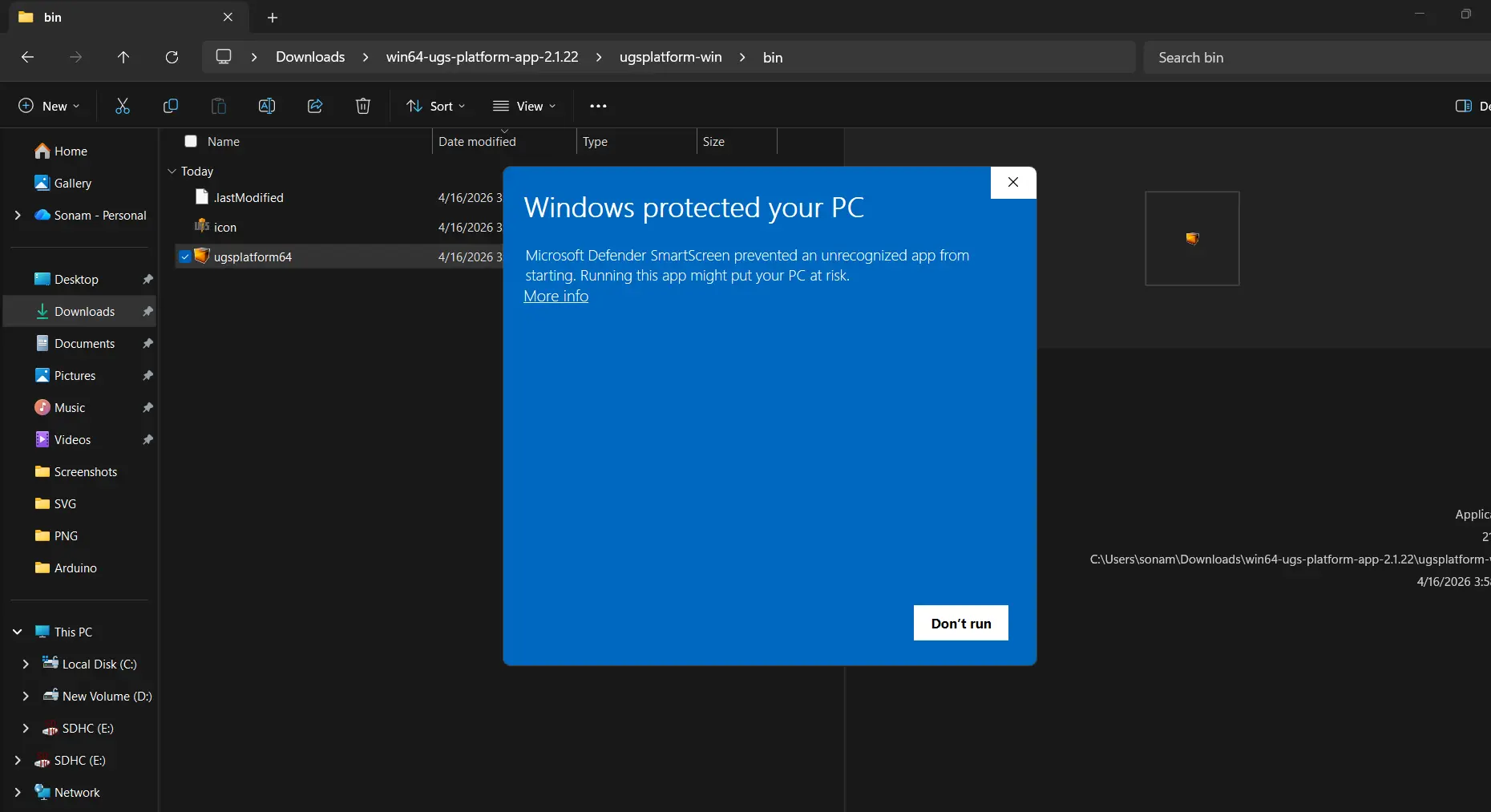
First launch showed a Windows security warning — clicked "More info" then "Run anyway".
I connected UGS to COM17 at 115200 baud. GRBL responded immediately. I used the Machine Control panel to jog X and Y — set feed rate to 1000 mm/min and step size to 10mm and both motors responded correctly to every button press.
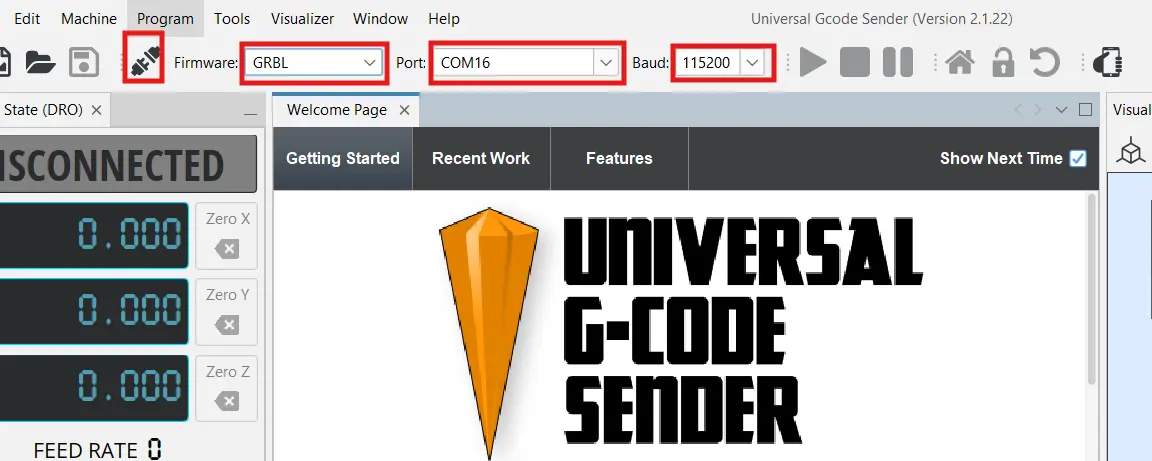
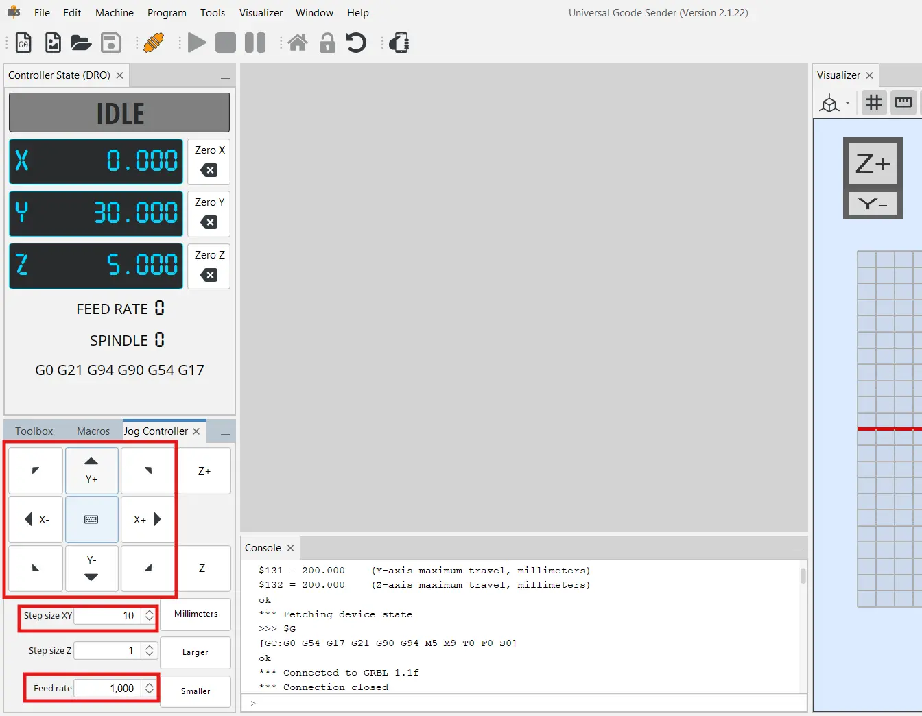
Motors responding to G-code commands through GRBL — that was a big moment. Everything from the PCB traces all the way up to the firmware layer was working.
Setting Up GRBL-Plotter
UGS is great for jogging but to actually send drawing files to the machine I needed something that generates G-code from a design. I initially looked into Inkscape extensions but most of them were built for older Inkscape versions and output Z-axis commands for pen up/down — not the M3/M5 servo commands my setup uses.
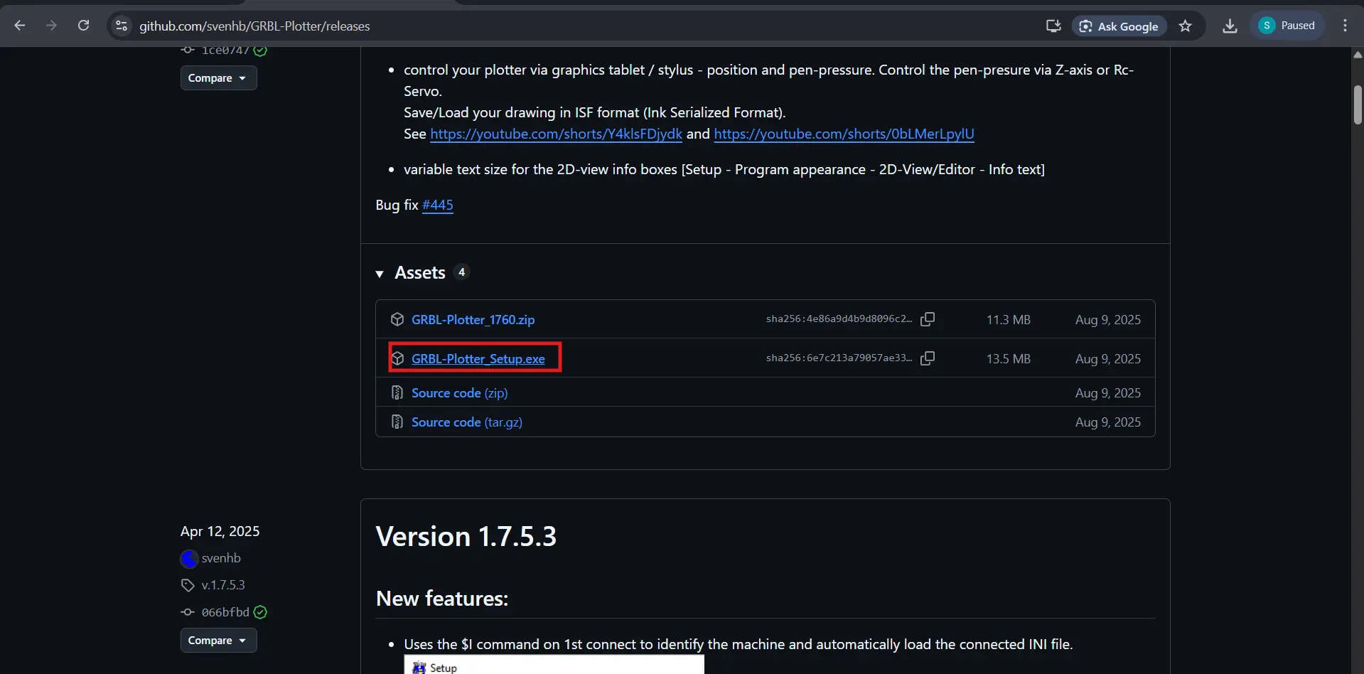
GRBL-Plotter was the better choice — it's an all-in-one tool that imports SVG files directly and has built-in servo pen up/down support. I downloaded it from the GRBL-Plotter GitHub releases page.
After connecting to COM17 at 115200 I went into the setup and configured the servo pen commands. I switched from Z-axis mode to PWM mode and set:
| Setting | Value |
|---|---|
| Pen UP (P90) | S100 |
| Pen DOWN (P92) | S30 |
| XY Feedrate | 2000 mm/min |
| G-code Header | G21; G90; M3 S100 |
| G-code Footer | M3 S100; G0 X0 Y0; M5 |
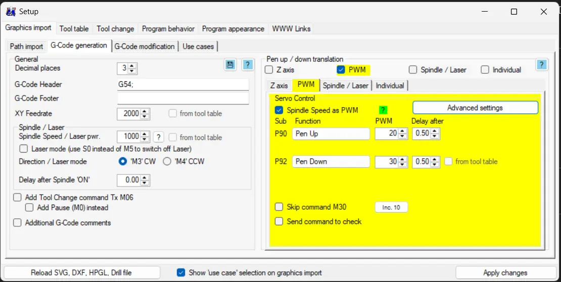
The G-code header lifts the pen before any movement starts and sets millimeter units and absolute positioning. The footer lifts the pen again, returns to home, then turns the servo off. These are important — without them the pen drags across the paper whenever the machine moves between shapes.
I also verified the servo S values by sending commands directly from GRBL-Plotter's console before running any files:
| Command | Result |
|---|---|
| M3 S100 | Pen UP ✅ |
| M3 S30 | Pen DOWN ✅ |
First G-code Test
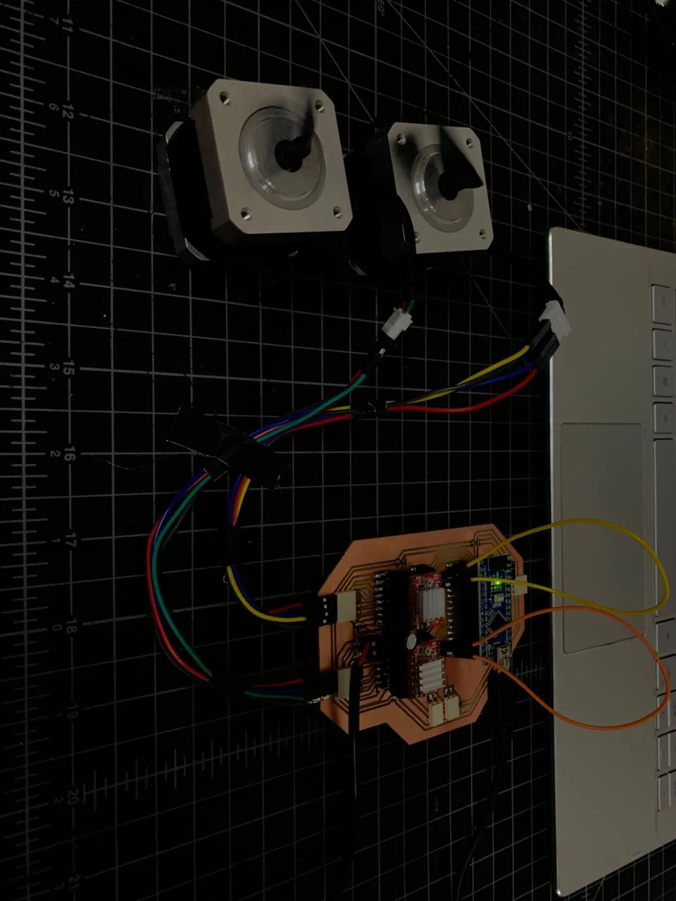
With everything configured I generated a text G-code file using GRBL-Plotter's built-in text tool and ran it to test all components working together end to end — both motors moving on X and Y, servo lifting and lowering the pen at the right moments, all coordinated through GRBL.
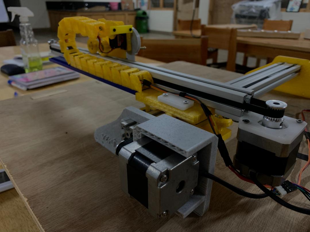
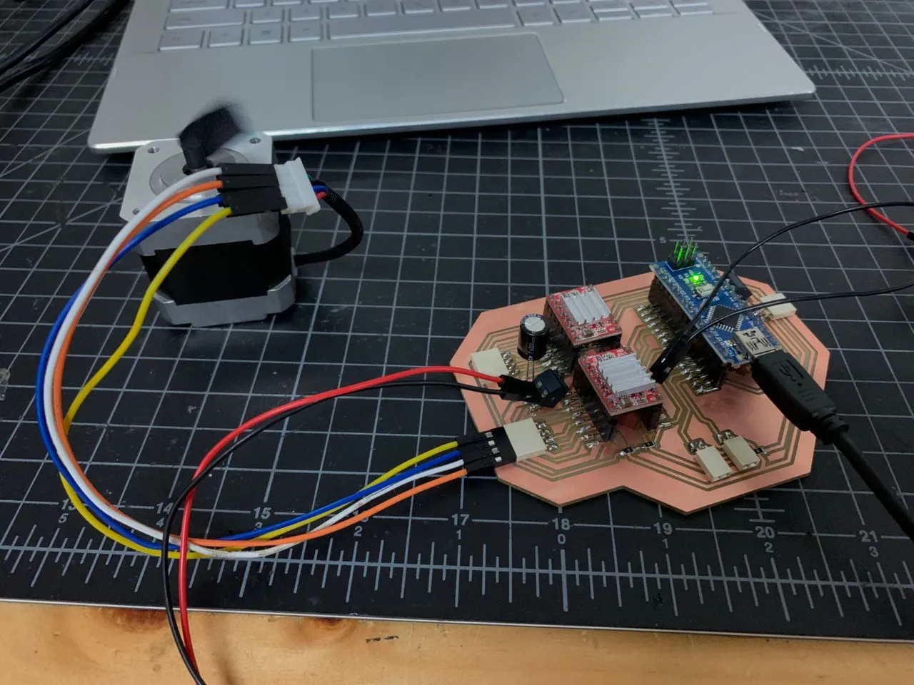
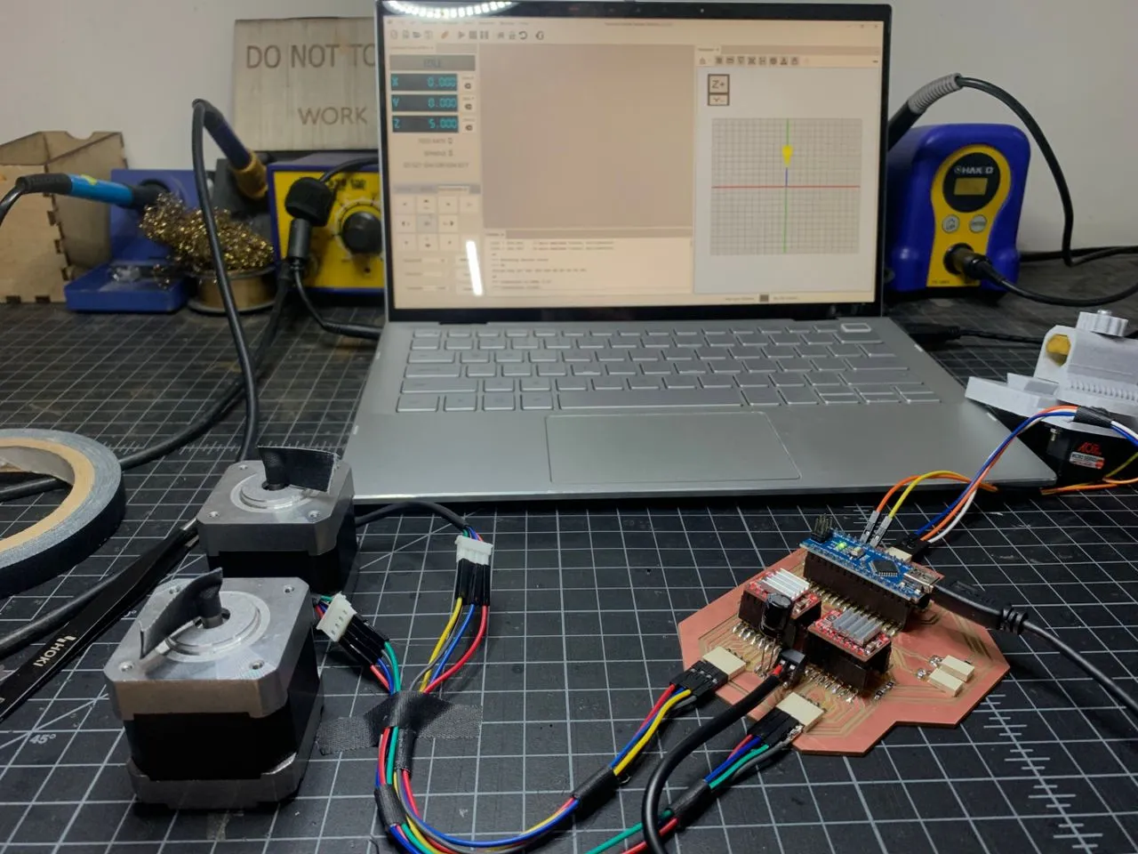
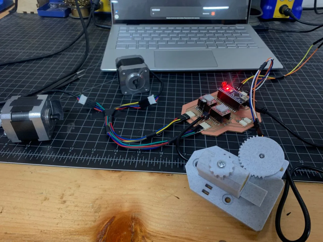
The frame isn't fully assembled yet at the time of writing — I'm running the motors, servo, and PCB off the bench for now — but all the electronics responded exactly as expected to the G-code commands.
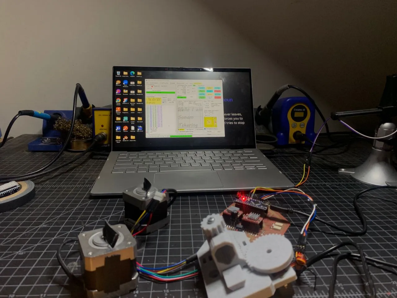
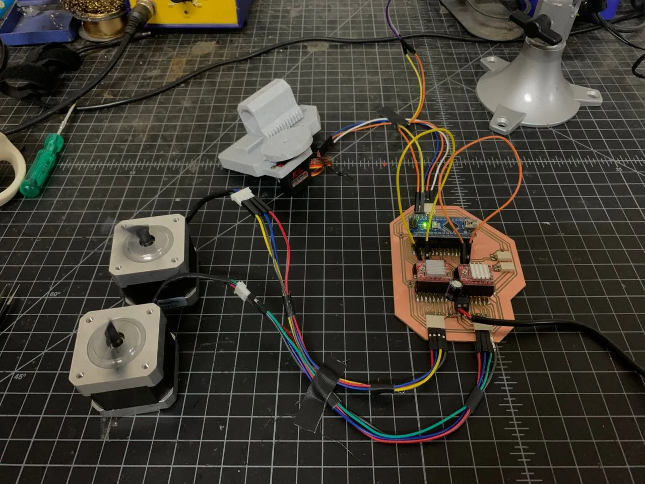
This is the full electronics setup on the bench:
After that I assembled the frame and also I designed and added a drag-chain for the servo wires.
Final Project Results