Vision Voice — Project Development
This page documents everything I've been building, testing, and learning as I work toward the final Vision Voice project. It's not always pretty and it's definitely not always smooth, but that's kind of the point. I'm keeping track of everything here so I can actually see how the project evolves over time.
Week 01 — Concept and Planning
Visualizing the Idea
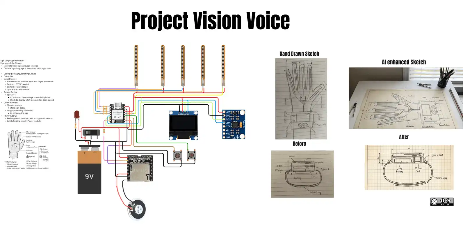
To clearly visualize my final project, I used Canva to jot down the ideas and features of Vision Voice.
Here is the link to my Canva for reference.
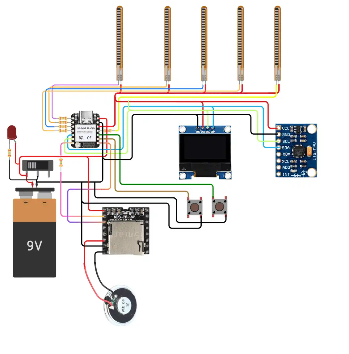
Circuit Draft
Using Canva I also made a draft of the circuit. The circuit is not finalized and I need to rework on it. ^o^
Here is the link to the detailed connection spreadsheet.
Week 02 — Cardboard Prototyping
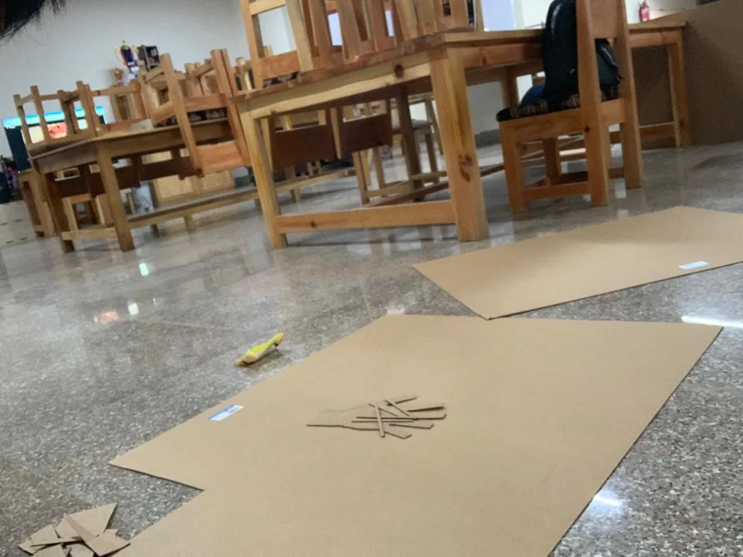
Today our local instructor guided us through the process of cardboard prototyping, which was both fun and interesting. We were given two hours to complete our first prototype for our final projects.
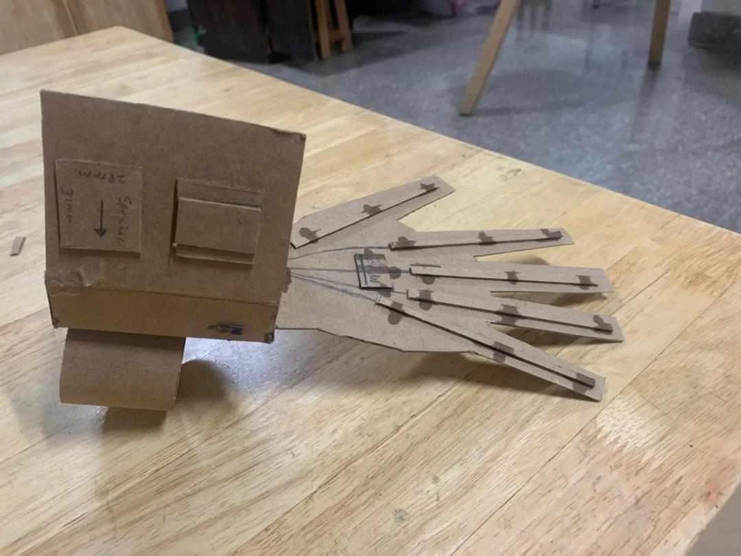
Hero Shot
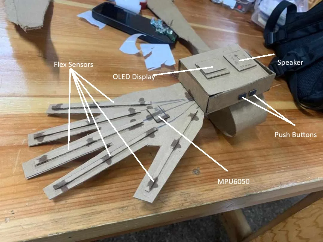
I started by making the glove and attaching the flex sensors.
Next I researched every component to find their specific dimensions — thickness, height, all of that. I carefully drew these dimensions onto the cardboard and cut them out using blades and scissors.
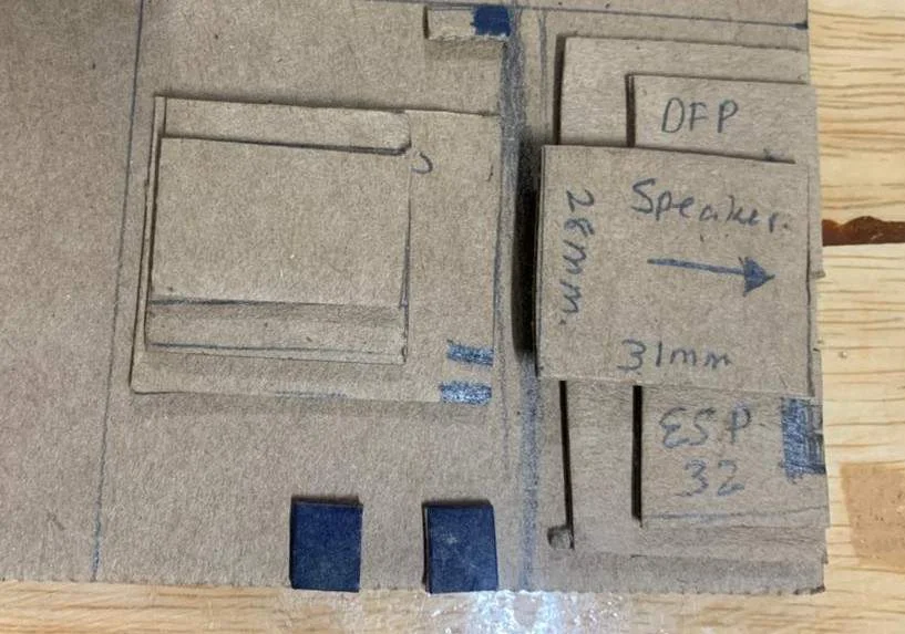
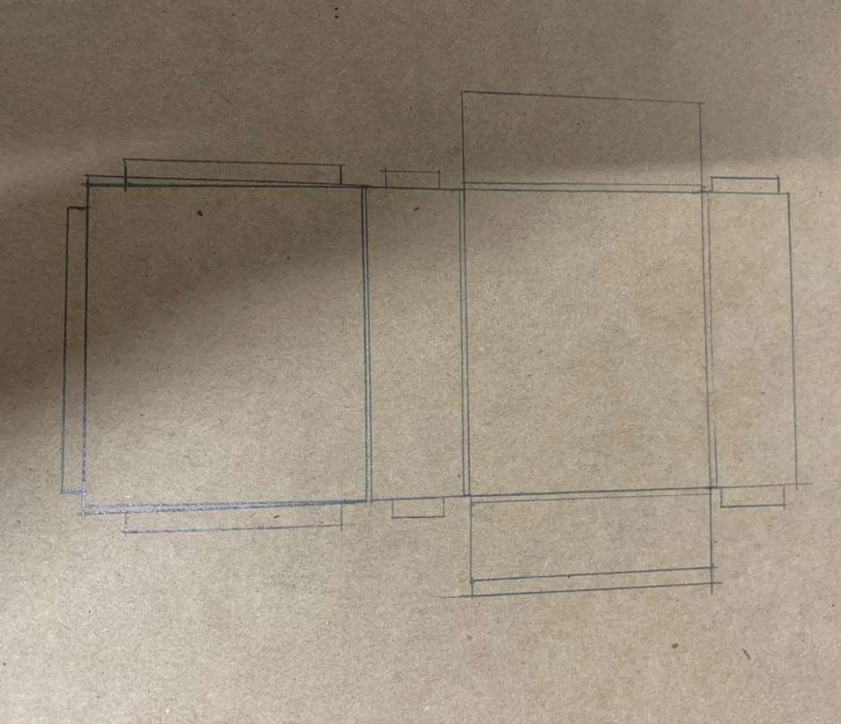
After that I estimated the size of the casing and drew it on the cardboard.
Once the pieces were ready I assembled everything to create the final structure.
Key Takeaways
These are the things I need to work on going forward:
Cloth Glove Fabrication — figuring out how to transition the design from cardboard to actual fabric.
Sensor Integration — determining the best method to securely attach the flex sensors to the cloth glove.
Casing Design and Wire Management — planning the internal layout of the casing to fit the PCB and organize wires neatly.
Accessibility Mechanism — designing a lid system (likely using screws) that allows easy access to the inside for maintenance.
Material Constraints — accounting for the specific thickness of final materials and hardware like screw sizes in the design.
Future Plans
Going forward I plan to make a working prototype with the cardboard and test my programs and connections.
Week 04 — First Electronics Test
Simulations and Prototyping
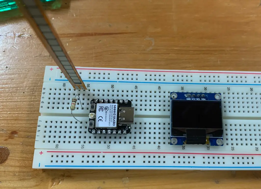
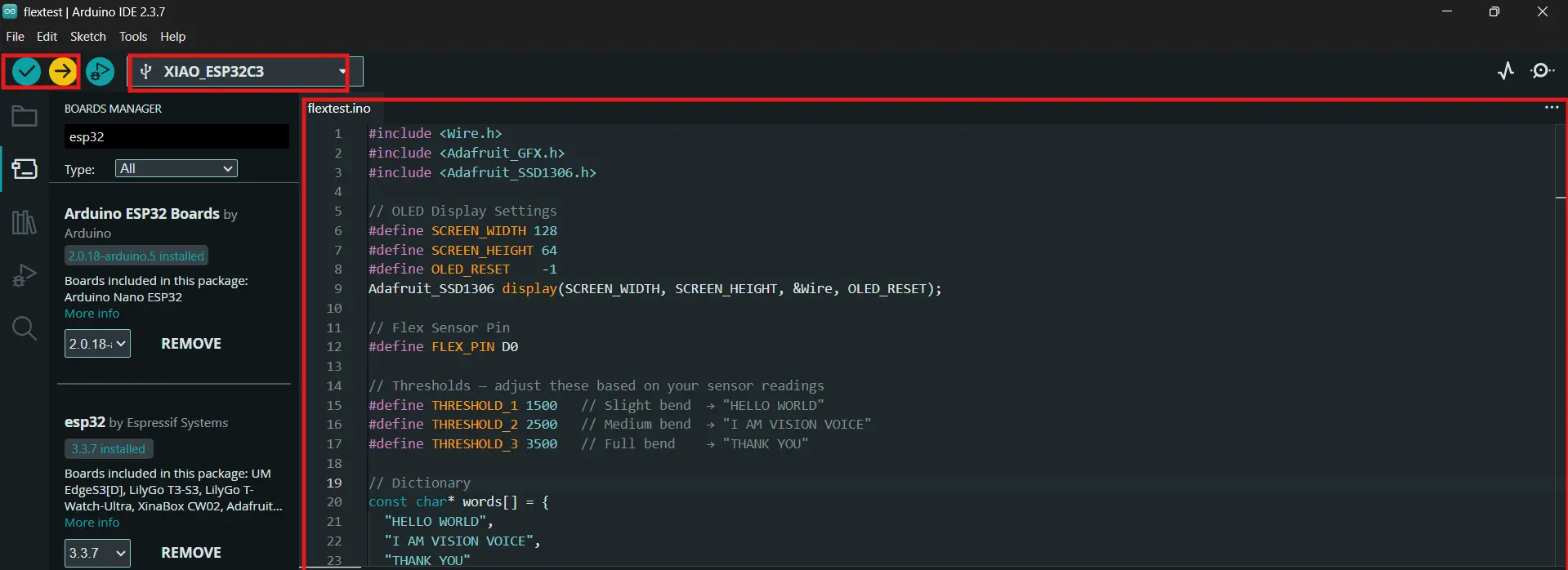
I wanted to make something for my final project. I wanted to use the XIAO ESP32-C3 board and display text when a certain value is reached from the flex sensor. This would help me understand the flex sensor values better, which is a really important part of the whole project.
I gathered all the components and made the circuit. The main purpose was to test the components and get familiar with the circuit.
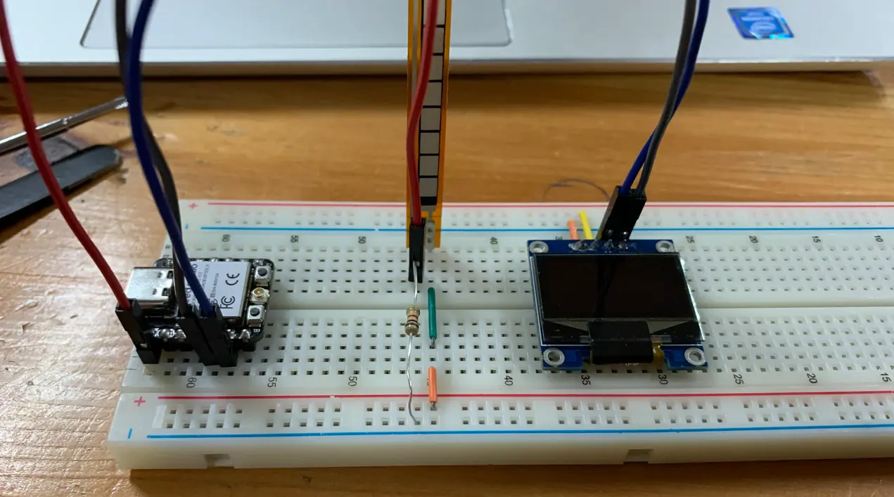
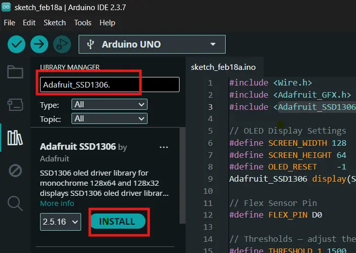
I downloaded the following libraries for the OLED display — Adafruit_GFX.h and Adafruit_SSD1306.h.
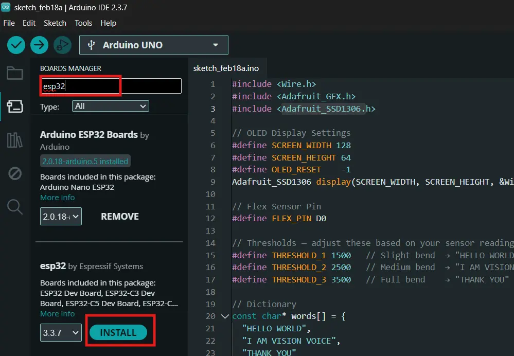
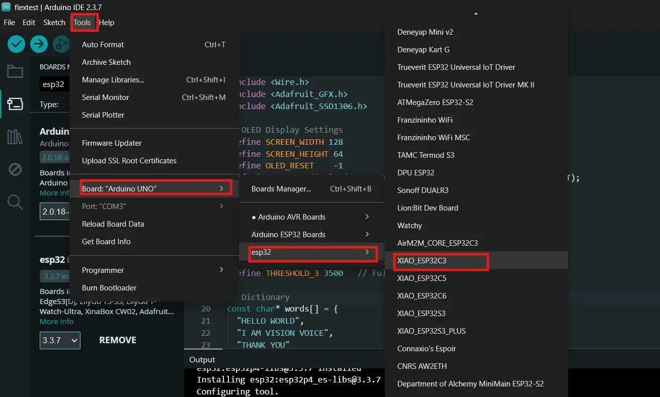
I then added the XIAO ESP32-C3 board to Arduino IDE using this link: https://raw.githubusercontent.com/espressif/arduino-esp32/gh-pages/package_esp32_dev_index.json
I added the link to the preference URL tab then downloaded the ESP32 from the Board Manager.

After installing all the libraries and setting up the board, I uploaded the code.
Code
#include <Wire.h>
#include <Adafruit_GFX.h>
#include <Adafruit_SSD1306.h>

#define SCREEN_WIDTH 128
#define SCREEN_HEIGHT 64
#define OLED_RESET    -1
Adafruit_SSD1306 display(SCREEN_WIDTH, SCREEN_HEIGHT, &Wire, OLED_RESET);

#define FLEX_PIN D0

#define IDLE_MIN    350
#define HELLO_MIN   280
#define VISION_MIN  200
#define THANKS_MIN  110

const char* words[] = {
  "HELLO WORLD",
  "I AM VISION VOICE",
  "THANK YOU"
};

int lastState = -1;

void displayWord(const char* word) {
  display.clearDisplay();
  display.setTextColor(SSD1306_WHITE);
  display.setTextWrap(true);

  int textSize = (strlen(word) > 9) ? 1 : 2;
  display.setTextSize(textSize);

  int16_t x1, y1;
  uint16_t w, h;
  display.getTextBounds(word, 0, 0, &x1, &y1, &w, &h);
  int yPos = (SCREEN_HEIGHT - h) / 2;
  int xPos = (SCREEN_WIDTH - w) / 2;
  if (xPos < 0) xPos = 0;

  display.setCursor(xPos, yPos);
  display.println(word);
  display.display();
}

void displayIdle() {
  display.clearDisplay();
  display.setTextSize(1);
  display.setTextColor(SSD1306_WHITE);
  display.setCursor(20, 28);
  display.println("Bend the sensor...");
  display.display();
}

void setup() {
  Serial.begin(115200);
  pinMode(FLEX_PIN, INPUT);

  if (!display.begin(SSD1306_SWITCHCAPVCC, 0x3C)) {
    Serial.println("SSD1306 allocation failed");
    while (true);
  }

  display.clearDisplay();
  display.setTextSize(2);
  display.setTextColor(SSD1306_WHITE);
  display.setCursor(10, 20);
  display.println("VISION");
  display.setCursor(30, 42);
  display.println("VOICE");
  display.display();
  delay(2000);

  displayIdle();
}

void loop() {
  int flexValue = analogRead(FLEX_PIN);

  Serial.print("Flex Value: ");
  Serial.println(flexValue);

  int currentState = -1;

  if (flexValue >= IDLE_MIN) {
    currentState = -1;
  } else if (flexValue >= HELLO_MIN) {
    currentState = 0;
  } else if (flexValue >= VISION_MIN) {
    currentState = 1;
  } else if (flexValue >= THANKS_MIN) {
    currentState = 2;
  }

  if (currentState != lastState) {
    if (currentState == -1) {
      displayIdle();
    } else {
      displayWord(words[currentState]);
    }
    lastState = currentState;
  }

  delay(100);
}
How the Code Works
The flex sensor gives different analog values depending on how much it's bent. I had to test it a bunch of times using Serial Monitor and note down what values came out at different bend positions. Here are the ranges I ended up with:
| Flex Value Range | Display |
|---|---|
| 350 – 360 | Idle (not bent) |
| 280 – 345 | "HELLO WORLD" |
| 200 – 275 | "I AM VISION VOICE" |
| 110 – 195 | "THANK YOU" |
I used a lastState variable to track what's currently on the display so it only updates when the state actually changes — this prevents flickering and makes the output much smoother.
The displayWord() function automatically sizes the text — shorter phrases get size 2 (big and readable), longer ones drop to size 1 so they fit on the 128x64 screen. It also centers the text using getTextBounds() to calculate the exact position.
Note that the code was written with the help of Claude AI, but I went through it line by line to understand what it was doing.
Result
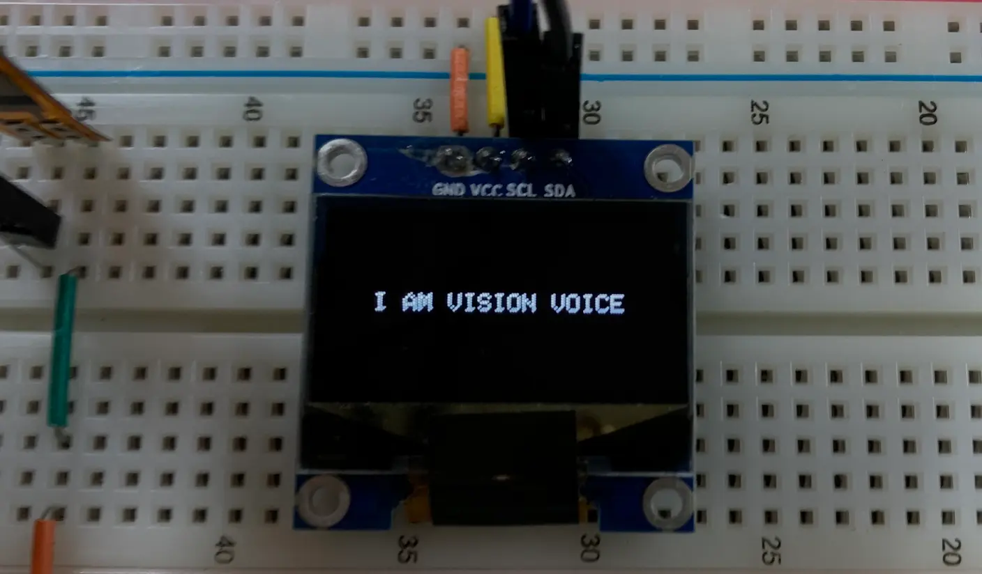
When I bend the flex sensor the text changes to the corresponding phrase. Yayyy! :D
Week 06 — PCB Design
This week I got to work on something directly related to Vision Voice — I designed my own PCB for the project!
I used KiCad to do the whole thing. I started by drawing out the schematic, placing all the components and wiring everything up. Since I was planning to use the XIAO ESP32-S3 but our lab didn't have it available, I went ahead with the ESP32 Wroom 32D instead.
After finishing the schematic and running the Electrical Rules Check, I mp4ed on to PCB routing — which was honestly the hardest part. It took around 10 hours to route all the traces and I ended up using 9 zero-ohm resistors as jumpers to get everything connected cleanly.
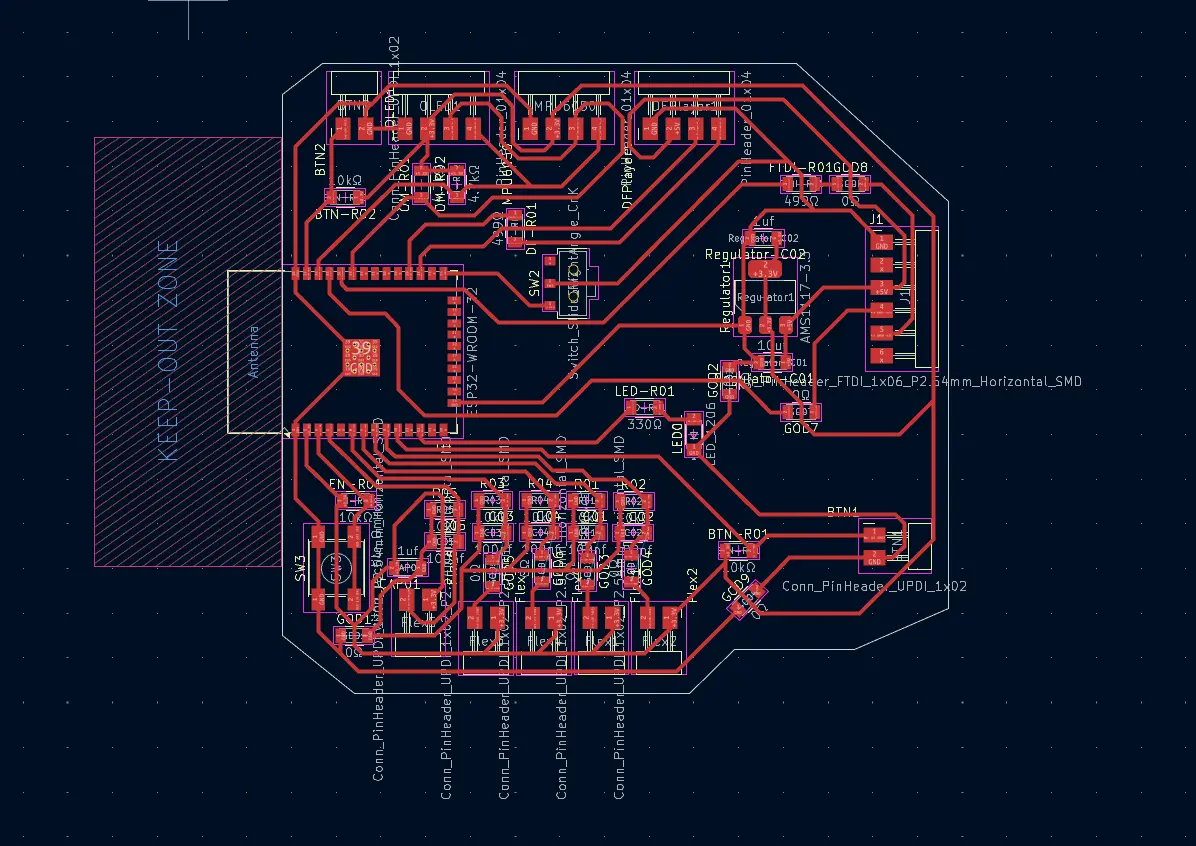
Once the routing was done I exported the PCB as an SVG, processed it in Inkscape to separate the interior and edge cut files, and then used Mods CE to generate the RML toolpaths for milling on the Roland SRM-20.
Here is the link to the full Week 06 documentation for more details.
Week 08 — Electronics Production
This week was all about actually making a PCB — milling it, soldering the components, and programming it. Honestly one of the most humbling weeks so far.
My original plan was to mill the final project board from Week 06, but after the first attempt the traces didn't come out well. I tried to redesign it but couldn't get it to work in time — so the final project board is something I'll have to start from scratch on later.
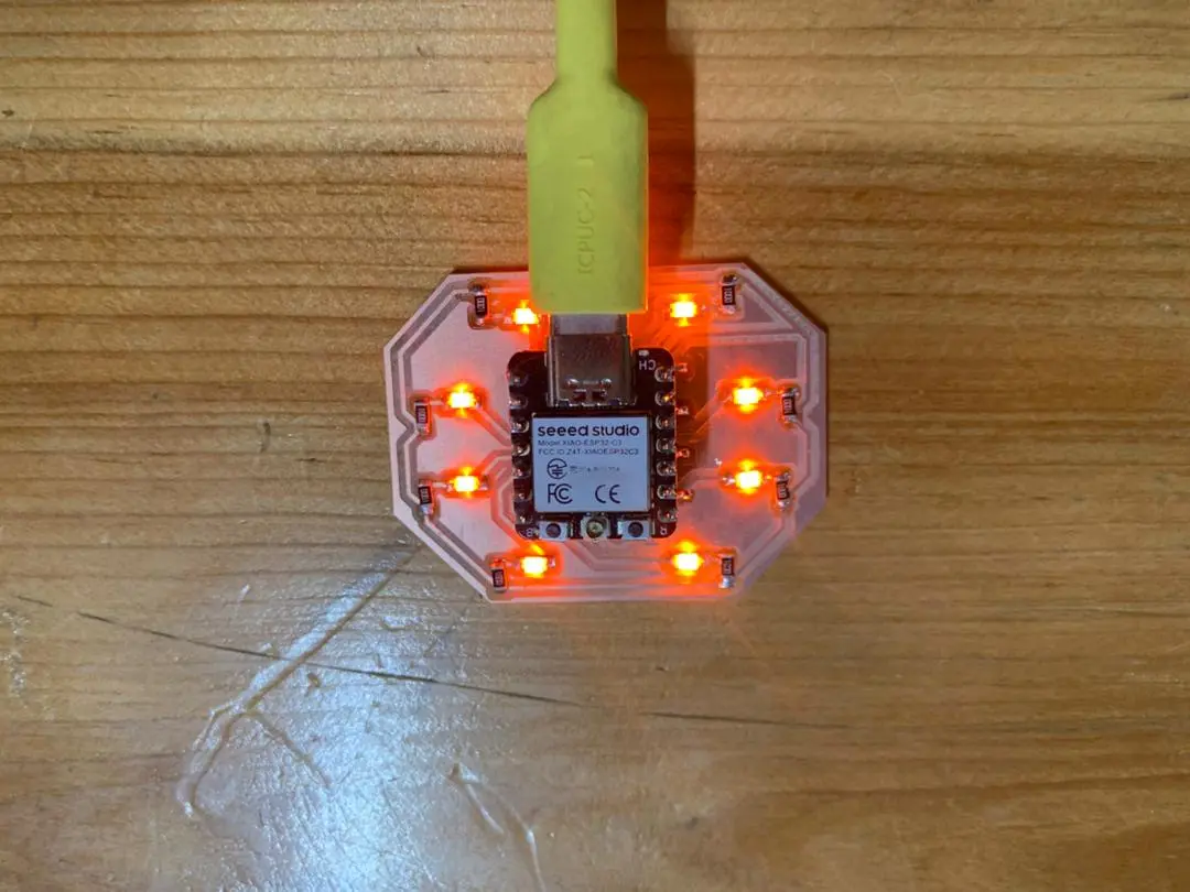
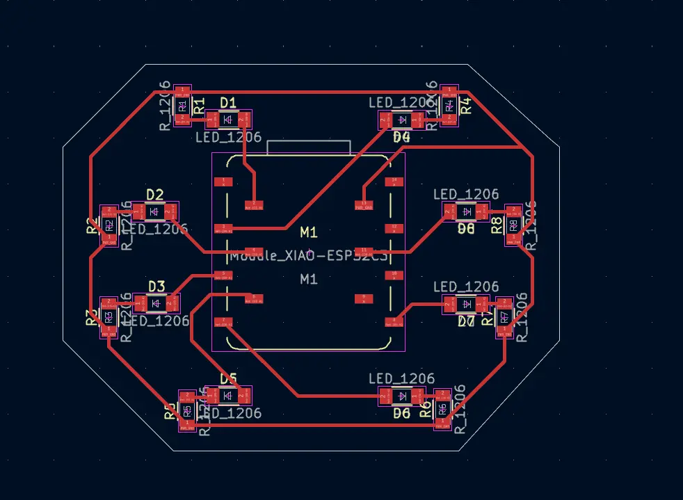
Since I still had the week's assignment to complete I went through 3 design iterations and ended up making a simpler board where I can program LEDs to make patterns. I had only 1 day left at that point so I grinded through the night to design, mill, solder, and program it all in time.
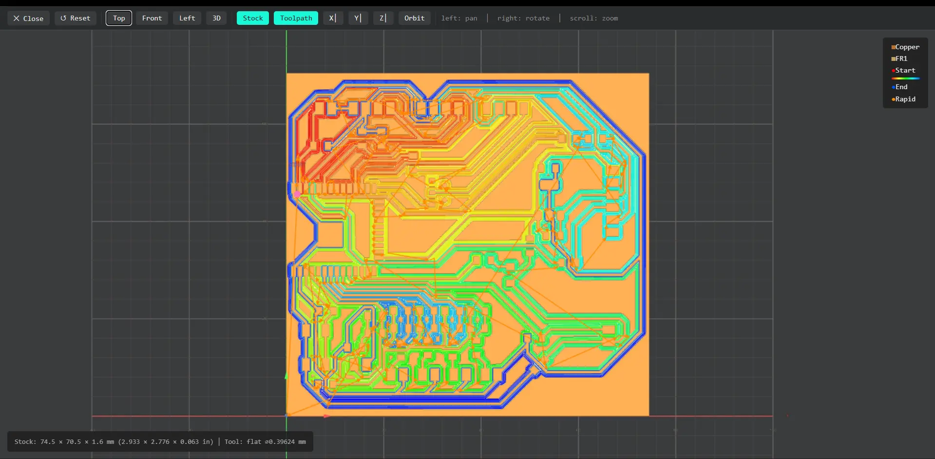
For milling I used the Roland SRM-20. The process involved exporting the design from KiCad as an SVG, preparing it in Inkscape, generating the RML toolpath in Mods CE, and then running it on the machine.
After milling I gathered all the components and soldered them onto the board. The soldering was actually the part I enjoyed most and it came out really clean!
For programming I used Arduino IDE with the XIAO ESP32-C3 and wrote the LED pattern code with the help of Claude AI — though I made sure to go through it line by line so I actually understood what it was doing.
Here is the link to the full Week 08 documentation for more details.
Component Testing — Vision Voice Hardware
While I was working on the hardware I started thinking about how Vision Voice is actually going to tell gestures apart. My early tests in Week 04 used fixed threshold ranges for a single flex sensor which worked fine for 3 phrases, but for ASL gestures with 5 fingers that approach is going to fall apart fast. Too many gestures look similar and hardcoded ranges just won't cut it.
So I did some research and landed on using a machine learning algorithm called kNN (k-Nearest Neighbors). Instead of hardcoding thresholds, I collect a bunch of real sensor readings for each gesture, store them as training data, and let the algorithm figure out the boundaries itself. When a new reading comes in it finds the closest match in the training data and says "that looks like this gesture."

This Image is Generated by Claude AI Click here to view the prompt.
Each gesture gets represented as 8 numbers — 5 flex sensor values (one per finger via the ADS1115 modules) and 3 accelerometer values from the MPU6050. Together those 8 numbers describe both the shape of the hand and how it's oriented in space, which should be enough to tell ASL gestures apart reliably.
For training I decided to go with a hybrid approach which is, collect data and train the model on my PC using Python, then export the trained model as a lookup table and flash it onto the XIAO so the glove runs fully standalone with no WiFi or phone needed. But before any of that can happen every single component needs to be confirmed working and reading clean reliable data. So I went through each part one by one and then slowly combined them. Here's how that went.
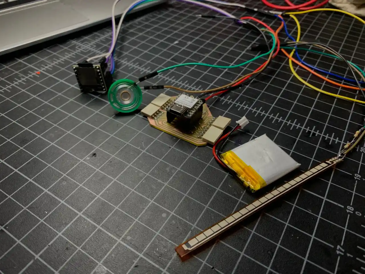
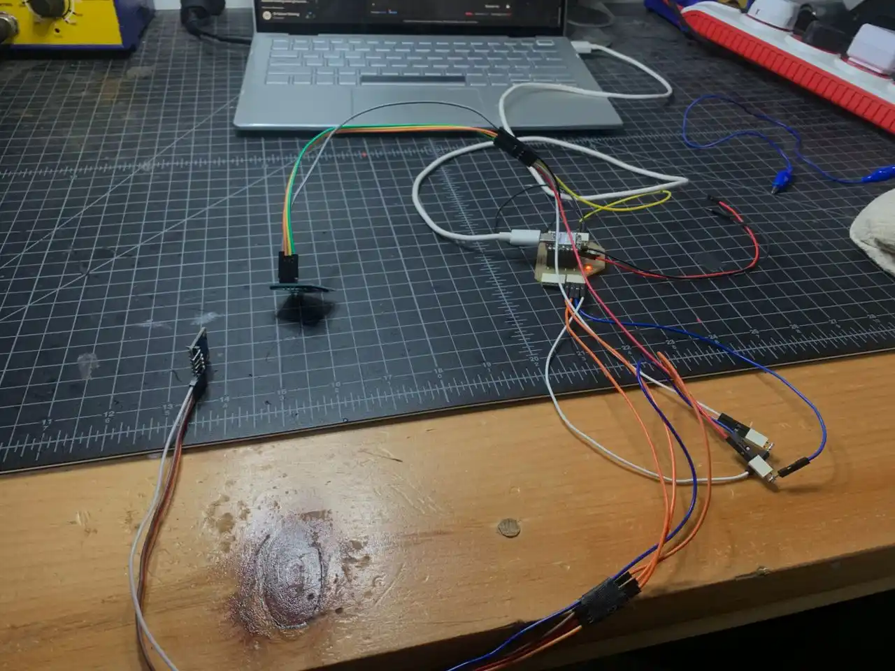
Test 1 — DFPlayer Mini + Flex Sensor + LiPo Battery
The first thing I wanted to test was the audio system because that's one of the most important parts of Vision Voice. If the DFPlayer doesn't work, the whole "voice" part falls apart.
Components
XIAO ESP32-C3, DFPlayer Mini, speaker, flex sensor, 47kΩ resistor, 1kΩ resistor, LiPo battery 3.7V, SD card.
Wiring
The DFPlayer communicates over UART so I connected it to the XIAO's hardware serial pins — D6 as TX and D7 as RX. The DFPlayer's RX pin needs a 1kΩ resistor in series to protect it. TX goes direct. The flex sensor uses a voltage divider with a 47kΩ pull-down resistor to A0.
| Component | Pin | XIAO ESP32-C3 |
|---|---|---|
| DFPlayer RX | → | D6 via 1kΩ |
| DFPlayer TX | → | D7 direct |
| DFPlayer VCC | → | LiPo positive (direct) |
| DFPlayer GND | → | GND |
| Speaker | → | SPK_1 + SPK_2 |
| Flex sensor signal | → | A0 |
| Flex sensor other leg | → | 47kΩ to GND |
One thing I ran into was that DFPlayer VCC can't go to the XIAO's 5V pin when running on battery. The 5V pin only outputs 5V when USB is connected — on battery it drops to whatever the LiPo is at and the DFPlayer stops responding. The fix was wiring DFPlayer VCC directly to the LiPo positive, bypassing the XIAO's 5V pin entirely. After that it worked fine on battery.
The SD card also needs to be formatted as FAT32 with audio files inside a folder called mp3. Files need to be named 0001.mp3, 0002.mp3 and so on. I had the format wrong at first and the DFPlayer just kept saying not found.
Calibrating the Flex Sensor
Before writing the full code I just printed raw values from the flex sensor to Serial Monitor to figure out the thresholds. I bent and straightened my finger slowly and watched the numbers:
Flex value: 2653   ← open hand (resting)
Flex value: 2651
Flex value: 2173   ← starting to close
Flex value: 1533
Flex value: 1053   ← fully closed fist
Flex value: 1007
Flex value: 1660   ← opening again
Flex value: 2490
Flex value: 2601   ← back to open
That's a really clean range — almost 1600 points of difference between open and closed. So I set the thresholds at:
| Gesture | Value | Threshold |
|---|---|---|
| OPEN hand | ~2650 | above 2000 |
| CLOSED fist | ~1000 | below 1400 |
| MID / transitioning | in between | 1400 to 2000 |
The gap between 1400 and 2000 is a dead zone so it doesn't false trigger when I'm halfway through a gesture.
Code
I used the DFRobotDFPlayerMini library. One thing worth noting is that SoftwareSerial doesn't exist on the ESP32, so I had to switch to HardwareSerial instead. That threw a compilation error at first but switching it fixed everything.
#include <HardwareSerial.h>
#include <DFRobotDFPlayerMini.h>

HardwareSerial mySerial(1);
DFRobotDFPlayerMini myDFPlayer;

const int FLEX_PIN = A0;
const int THRESHOLD_OPEN   = 2000;
const int THRESHOLD_CLOSED = 1400;

bool isPlaying = false;
int currentTrack = 1;
const int TOTAL_TRACKS = 3;

void setup() {
  Serial.begin(115200);
  mySerial.begin(9600, SERIAL_8N1, D7, D6);

  if (!myDFPlayer.begin(mySerial)) {
    Serial.println("DFPlayer not found!");
    while (true);
  }
  myDFPlayer.volume(25);
}

void loop() {
  int val = analogRead(FLEX_PIN);

  if (val < THRESHOLD_CLOSED) {
    if (!isPlaying) {
      myDFPlayer.play(currentTrack);
      currentTrack++;
      if (currentTrack > TOTAL_TRACKS) currentTrack = 1;
      isPlaying = true;
    }
  } else if (val > THRESHOLD_OPEN) {
    if (isPlaying) {
      myDFPlayer.stop();
      isPlaying = false;
    }
  }
  delay(200);
}
The isPlaying flag is important — without it the code spams play() every 200ms while my fist is closed and the DFPlayer gets confused and skips tracks.
Result
Closing my fist plays the audio, opening my hand stops it. I had 3 files on the SD card and each fist close cycles to the next track. Everything worked on battery too after fixing the VCC wiring. The audio system for Vision Voice is confirmed working yay!! :D
Test 2 — MPU6050 + OLED SSD1306
After the audio system I mp4ed on to the sensor and display side. The MPU6050 gives me hand orientation data (accel X/Y/Z) which is part of the 8 features I'll use for gesture recognition later. The OLED is what shows the predicted gesture text to the person reading.
Components
XIAO ESP32-C3, MPU6050, OLED SSD1306 0.96".
Wiring
Both the MPU6050 and the OLED use I2C so they share the same two pins — SDA on D4 and SCL on D5. They just need different I2C addresses so they don't clash with each other.
| Component | SDA | SCL | VCC | GND |
|---|---|---|---|---|
| OLED SSD1306 | D4 | D5 | 3.3V | GND |
| MPU6050 | D4 | D5 | 3.3V | GND |
Before assuming the default addresses I scanned the I2C bus first to confirm:
Good — defaults confirmed, no address conflicts.
Libraries
Adafruit MPU6050, Adafruit SSD1306, Adafruit GFX Library, Adafruit Unified Sensor — all installed through the Arduino Library Manager.
Result
The OLED showed live accelerometer values and responded correctly when I tilted the board. Ay reads around 9.8 when flat which is grmp4ty, and the values shift as expected when I rotate in different directions:
Ax:-0.01 Ay:-8.73 Az:-4.65 | Gx:-0.26 Gy:-0.02 Gz:-0.25
Ax:0.04  Ay:-8.72 Az:-4.70 | Gx:-0.26 Gy:-0.02 Gz:-0.25
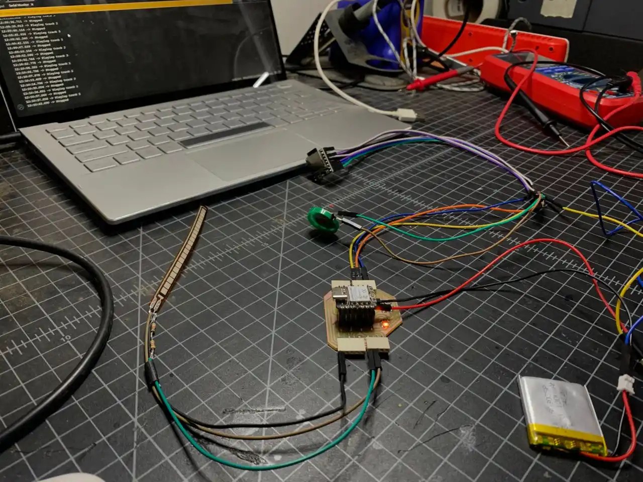
Test 3 — All Components Together (Without Button)
Once I confirmed everything worked individually I put it all together — flex sensor, MPU6050, OLED, DFPlayer, speaker, and LiPo all running on one XIAO at the same time.
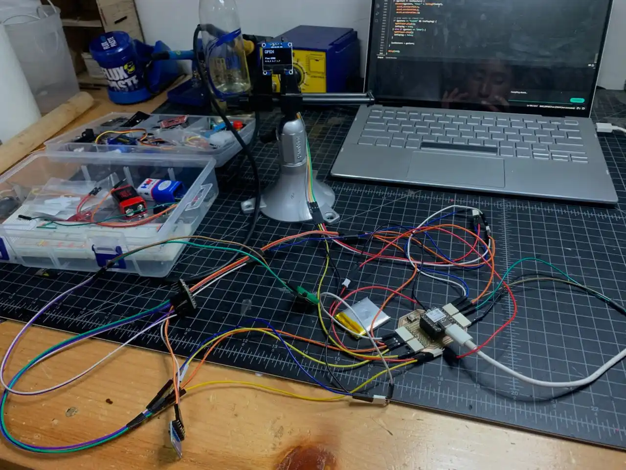
The OLED shows the current gesture in big text, the flex value, and the live accel X/Y/Z below it. The display updates every 200ms so the accel values are always fresh even when the gesture isn't changing. The DFPlayer triggers automatically when I close my fist.
One issue I ran into — the accel values on the OLED were only updating when the gesture changed. That was because I was calling showOLED() only inside the if (gesture != lastGesture) block. The fix was mp4ing the OLED update outside that block so it refreshes every loop, while keeping the DFPlayer trigger inside the gesture change block so audio doesn't spam.
The serial output looked like this with everything running:
Flex:2622 | Gesture:OPEN | Ax:1.04 Ay:9.82 Az:-1.34
Flex:2623 | Gesture:OPEN | Ax:1.05 Ay:9.82 Az:-1.38
Flex:2622 | Gesture:OPEN | Ax:-2.83 Ay:-6.51 Az:6.65
Flex:2621 | Gesture:OPEN | Ax:9.90 Ay:1.61 Az:0.32
You can see the accel values changing as I was mp4ing the board around while the gesture stayed OPEN. That's exactly the kind of data I'll be collecting for the kNN training later.
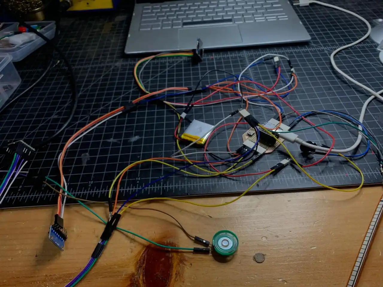
Test 4 — Full System with Button
The last thing to add was the push button on D1. In Vision Voice the button does two things — a short press to manually trigger audio for the current detected gesture, and a long press held for 2 seconds to calibrate.
The button wiring is simple — one leg to D1, other leg to GND. No external resistor needed because I use the XIAO's internal pull-up resistor in the code.
What the Final Combined Sketch Does
- Boots with "VISION VOICE" splash screen on OLED
- Shows a clear error on OLED if any component fails on startup
- Live gesture detection from flex sensor (OPEN / MID / CLOSED)
- Live accel X/Y/Z updating on OLED every 200ms
- Auto plays audio when fist closes
- Short button press triggers audio manually
- Long button press (2 seconds) shows calibrate screen
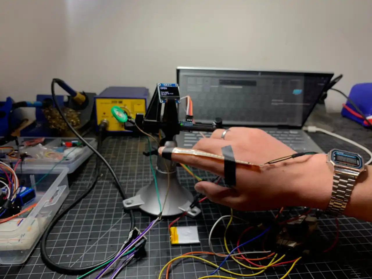
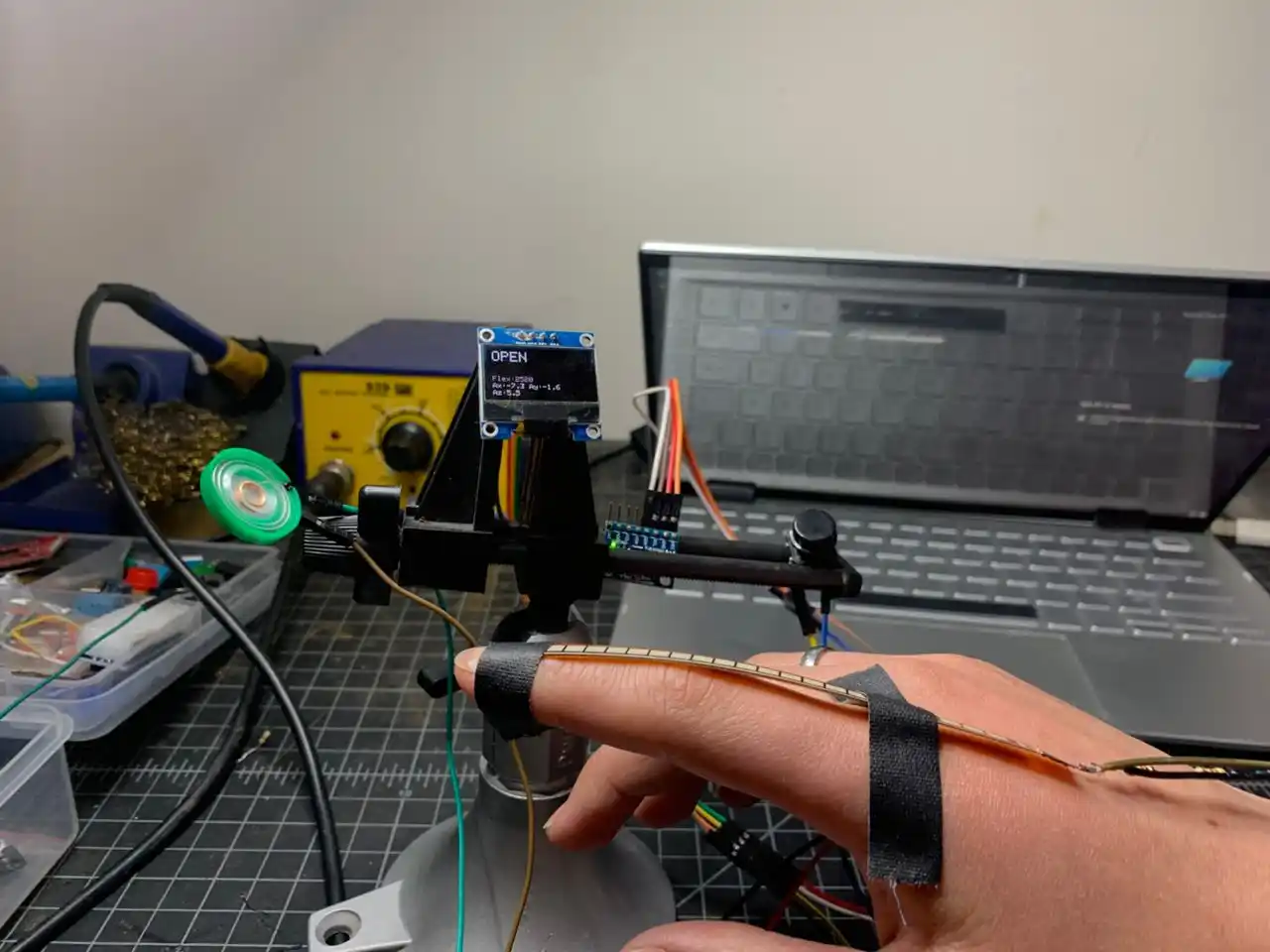
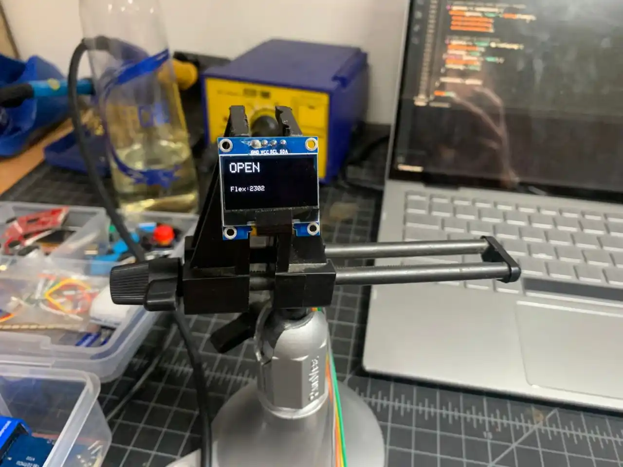
The OLED is showing "OPEN" with the live flex value and accel values while I hold the flex sensor on my finger. That's basically Vision Voice working in prototype form with one finger sensor. When the ADS1115 modules arrive I'll scale this up to all 5 fingers.
Full Combined Code
#include <Wire.h>
#include <HardwareSerial.h>
#include <Adafruit_GFX.h>
#include <Adafruit_SSD1306.h>
#include <Adafruit_MPU6050.h>
#include <Adafruit_Sensor.h>
#include <DFRobotDFPlayerMini.h>

#define SCREEN_WIDTH 128
#define SCREEN_HEIGHT 64
#define OLED_RESET -1
Adafruit_SSD1306 display(SCREEN_WIDTH, SCREEN_HEIGHT, &Wire, OLED_RESET);
Adafruit_MPU6050 mpu;

HardwareSerial mySerial(1);
DFRobotDFPlayerMini myDFPlayer;

const int FLEX_PIN = A0;
const int BUTTON_PIN = D1;
const int THRESHOLD_OPEN   = 2000;
const int THRESHOLD_CLOSED = 1400;

String lastGesture = "";
bool isPlaying = false;
unsigned long pressStart = 0;
bool buttonHeld = false;

void showOLED(String line1, String line2, float ax, float ay, float az) {
  display.clearDisplay();
  display.setTextColor(SSD1306_WHITE);
  display.setTextSize(2);
  display.setCursor(0, 0);
  display.println(line1);
  display.setTextSize(1);
  display.setCursor(0, 36);
  display.println(line2);
  display.setCursor(0, 46);
  display.print("Ax:");
  display.print(ax, 1);
  display.print(" Ay:");
  display.println(ay, 1);
  display.setCursor(0, 56);
  display.print("Az:");
  display.println(az, 1);
  display.display();
}

void showMessage(String line1, String line2) {
  display.clearDisplay();
  display.setTextColor(SSD1306_WHITE);
  display.setTextSize(2);
  display.setCursor(0, 10);
  display.println(line1);
  display.setTextSize(1);
  display.setCursor(0, 48);
  display.println(line2);
  display.display();
}

void setup() {
  Serial.begin(115200);
  Wire.begin(D4, D5);
  pinMode(BUTTON_PIN, INPUT_PULLUP);

  if (!display.begin(SSD1306_SWITCHCAPVCC, 0x3C)) {
    Serial.println("OLED not found!");
    while (true);
  }

  display.clearDisplay();
  display.setTextSize(2);
  display.setTextColor(SSD1306_WHITE);
  display.setCursor(10, 10);
  display.println("VISION");
  display.setCursor(10, 36);
  display.println("VOICE");
  display.display();
  delay(2000);

  if (!mpu.begin()) {
    Serial.println("MPU6050 not found!");
    showMessage("ERROR", "MPU6050 fail!");
    while (true);
  }
  mpu.setAccelerometerRange(MPU6050_RANGE_8_G);
  mpu.setGyroRange(MPU6050_RANGE_500_DEG);
  mpu.setFilterBandwidth(MPU6050_BAND_21_HZ);
  Serial.println("MPU6050 ready!");

  mySerial.begin(9600, SERIAL_8N1, D7, D6);
  if (!myDFPlayer.begin(mySerial)) {
    Serial.println("DFPlayer not found!");
    showMessage("ERROR", "DFPlayer fail!");
    while (true);
  }
  myDFPlayer.volume(25);
  Serial.println("DFPlayer ready!");

  showMessage("READY!", "Press to speak");
  delay(1500);
}

void loop() {
  int flexVal = analogRead(FLEX_PIN);

  sensors_event_t accel, gyro, temp;
  mpu.getEvent(&accel, &gyro, &temp);

  String gesture = "";
  if (flexVal < THRESHOLD_CLOSED) {
    gesture = "CLOSED";
  } else if (flexVal > THRESHOLD_OPEN) {
    gesture = "OPEN";
  } else {
    gesture = "MID";
  }

  Serial.printf("Flex:%d | Gesture:%s | Ax:%.2f Ay:%.2f Az:%.2f\n",
    flexVal, gesture.c_str(),
    accel.acceleration.x,
    accel.acceleration.y,
    accel.acceleration.z);

  showOLED(gesture, "Flex:" + String(flexVal),
    accel.acceleration.x,
    accel.acceleration.y,
    accel.acceleration.z);

  if (gesture != lastGesture) {
    if (gesture == "CLOSED" && !isPlaying) {
      myDFPlayer.play(1);
      isPlaying = true;
    } else if (gesture == "OPEN") {
      myDFPlayer.stop();
      isPlaying = false;
    }
    lastGesture = gesture;
  }

  int btnState = digitalRead(BUTTON_PIN);

  if (btnState == LOW) {
    if (!buttonHeld) {
      pressStart = millis();
      buttonHeld = true;
    }
    if (millis() - pressStart >= 2000) {
      Serial.println("LONG PRESS → CALIBRATE");
      showMessage("CALIBRATE", "Resetting...");
      delay(1500);
      buttonHeld = false;
    }
  } else {
    if (buttonHeld) {
      unsigned long pressDuration = millis() - pressStart;
      if (pressDuration < 2000) {
        Serial.println("SHORT PRESS → SPEAK");
        showMessage("SPEAK!", gesture + " detected");
        myDFPlayer.play(1);
        isPlaying = true;
        delay(1500);
      }
      buttonHeld = false;
    }
  }

  delay(50);
}
Component Test Summary
| Component | Status |
|---|---|
| Flex sensor (1x on A0) | ✅ calibrated, thresholds confirmed |
| MPU6050 accel X/Y/Z | ✅ live values, responds to tilt |
| OLED SSD1306 | ✅ splash screen and live data working |
| DFPlayer Mini + SD card | ✅ plays and cycles through tracks |
| LiPo battery | ✅ direct wired to BAT pin |
| Button short press | ✅ triggers audio manually |
| Button long press | ✅ shows calibrate screen |
| All components together | ✅ full combined sketch working |
What's Next
I'm still waiting for the ADS1115 ADC modules to arrive. Those are needed to read all 5 flex sensors at the same time since the XIAO only has one analog input pin. Once those arrive the plan is:
testing all 5 flex sensors together via both ADS1115 modules (I2C 0x48 and 0x49), confirming there are no I2C address conflicts with the OLED and MPU6050 already on the bus, then mp4ing into collecting training data for the kNN gesture model, and finally training and deploying the gesture recognition system using the hybrid approach — train on PC with Python sklearn, export weights, flash to XIAO so it runs fully standalone.
Final Project PCB Design
While waiting for the ADS1115 modules, I went ahead and started designing the final PCB for Vision Voice. The goal was to create a compact board that can fit inside the glove's wrist casing and connect all the components together cleanly.
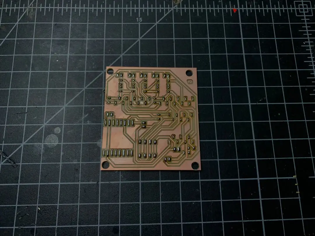
Here is the Hero shot of the PCB!!
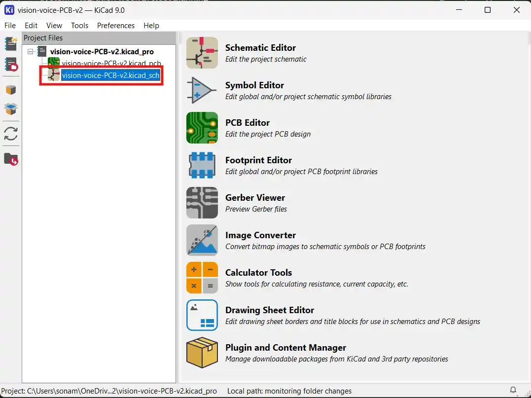
For the designing as usual I used KiCad. I first made a project folder for the PCB.
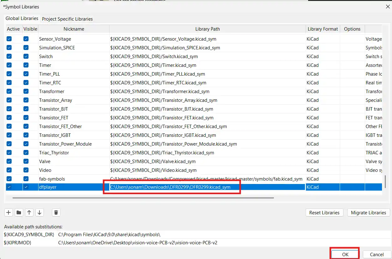
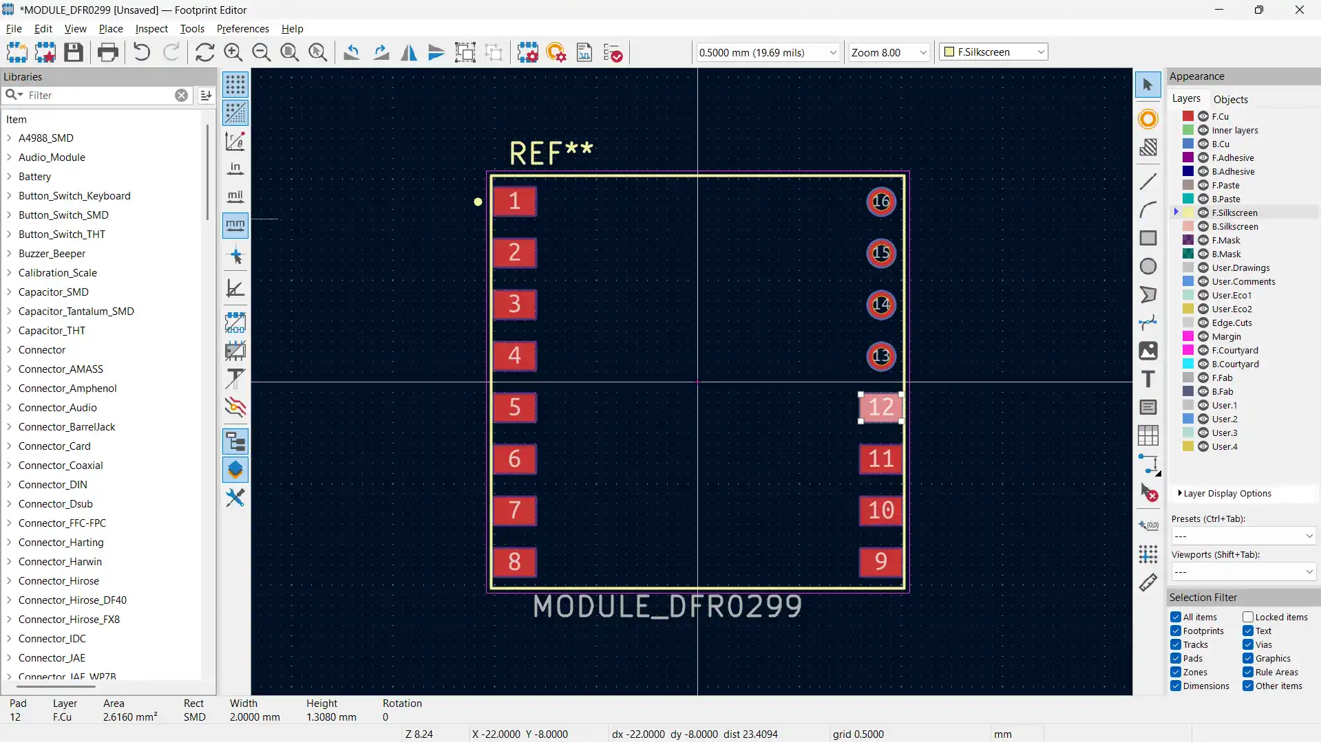
Then I started by getting the symbols and footprints for all the components that I needed for the PCB. I didn't have the symbol and footprint for the DFPlayer Mini so I had to make it myself using the footprint editor.
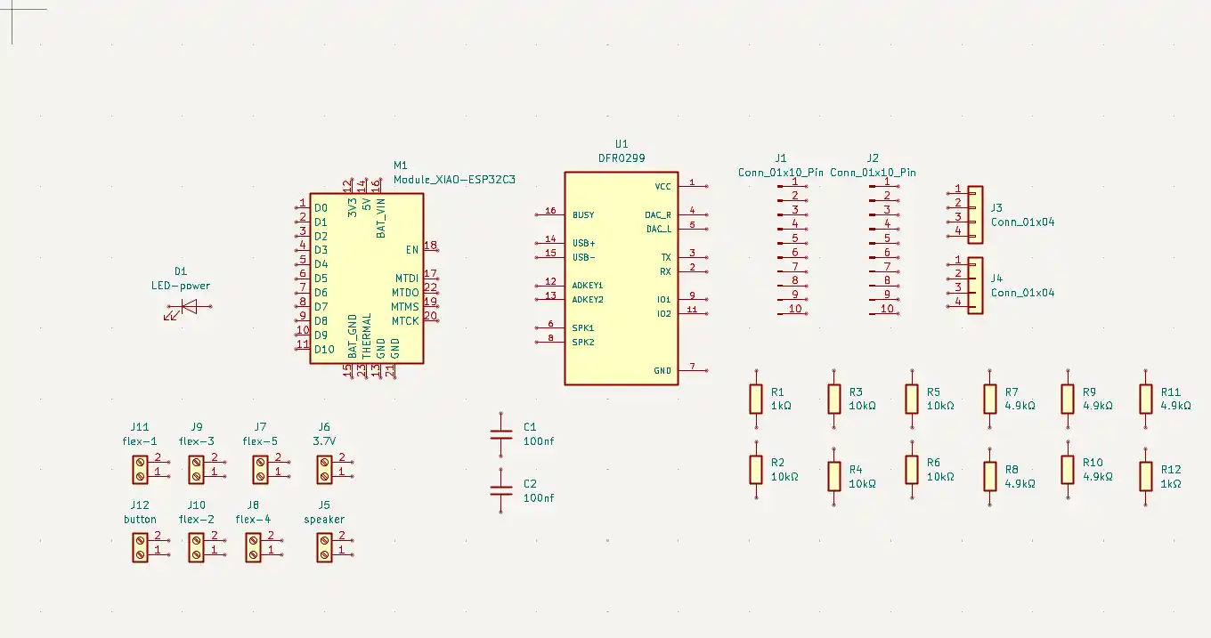
After that I added all the components to the schematic.
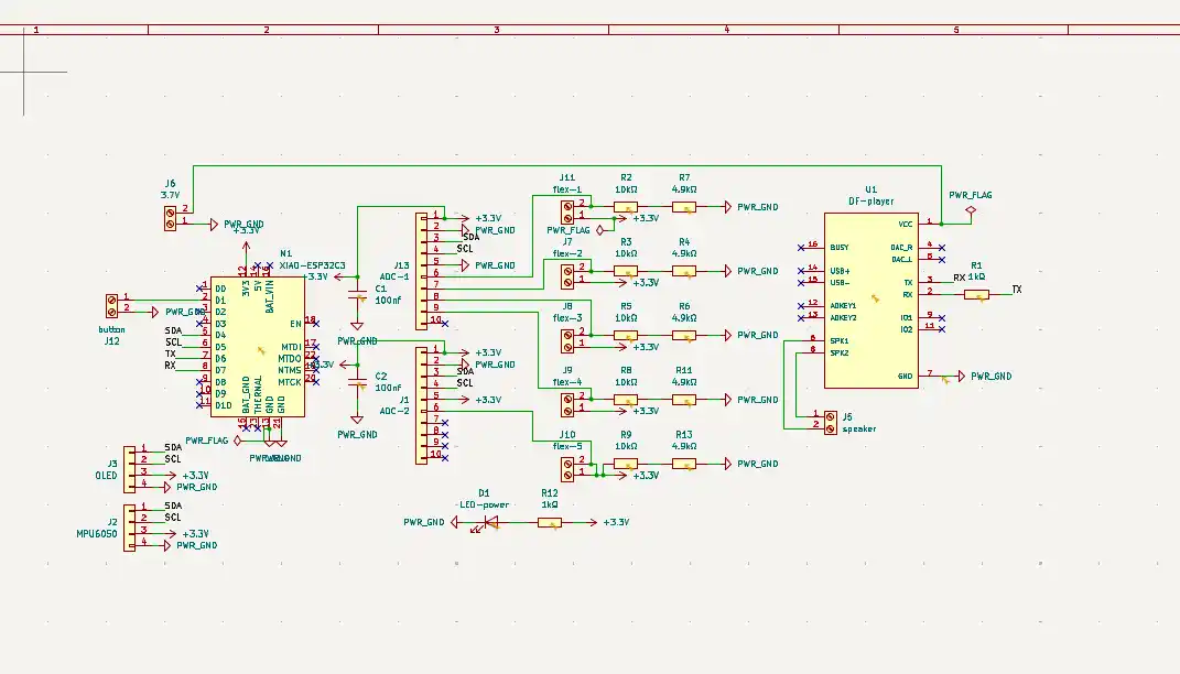
I then wired up all the components together. I used the net labels to make the wiring cleaner and easier to read.
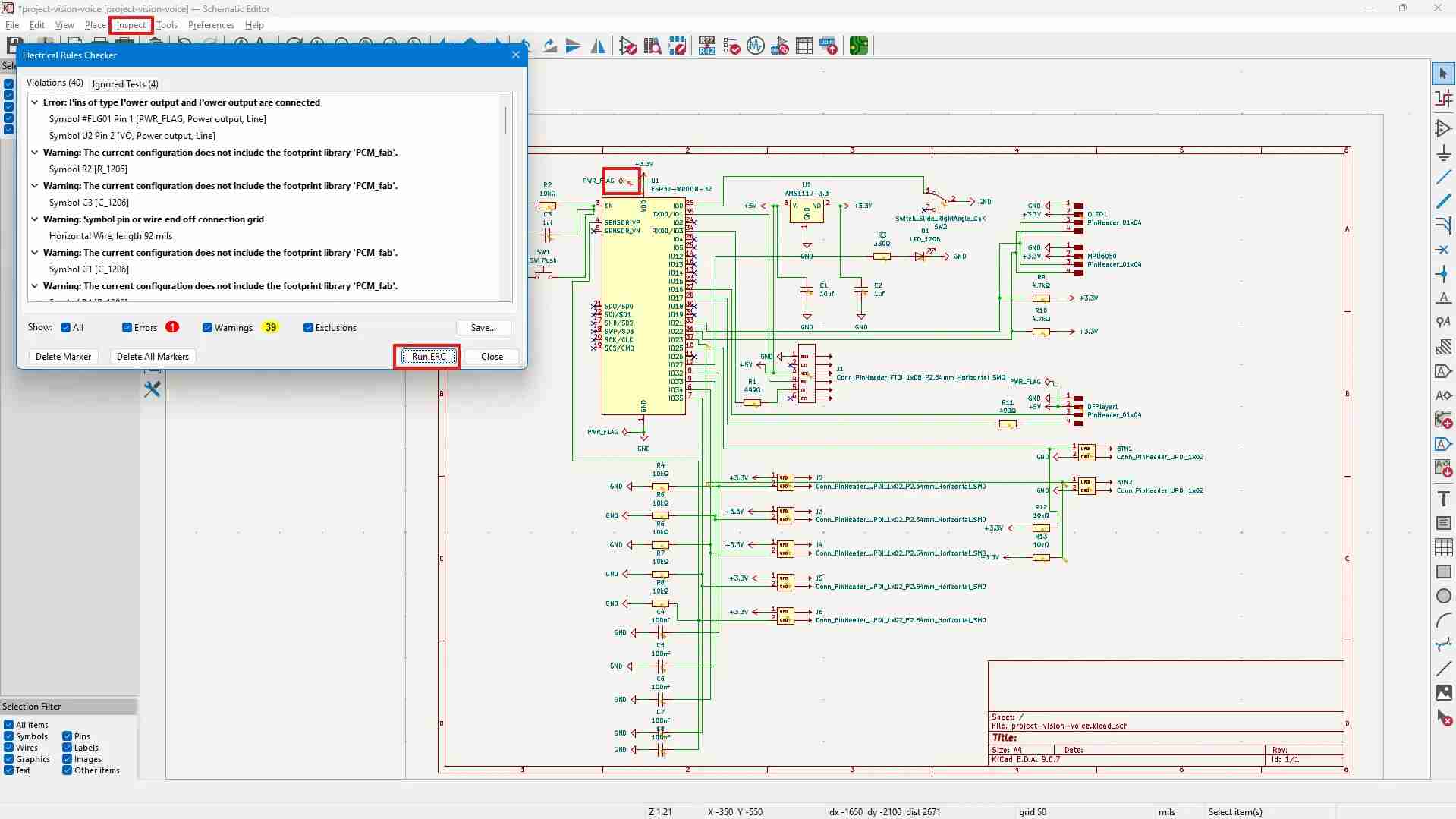
Using the ERC tool, I checked if there were any errors in the schematic and fixed them. Here is the result of the ERC check:
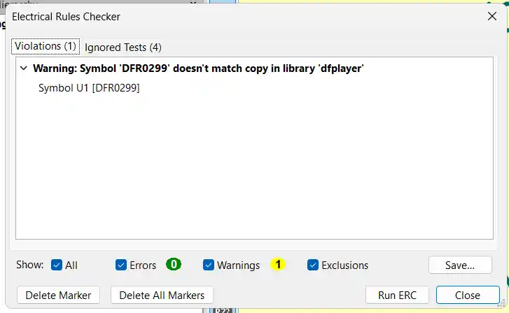
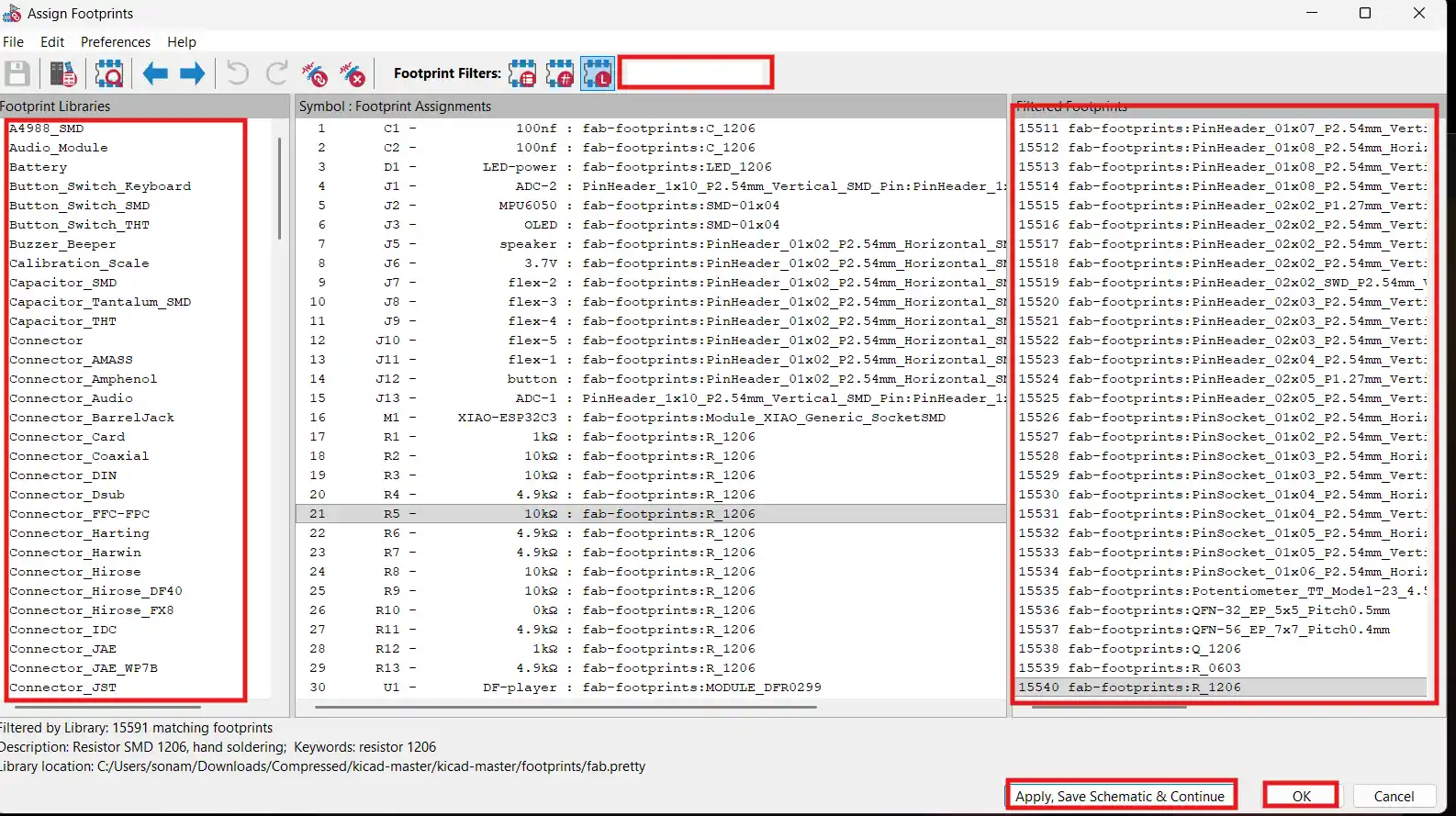
I used the assign footprints tool to assign the footprints to the symbols. I made sure to assign the correct footprint to each symbol, especially for the components that have multiple footprints like the resistors and capacitors.
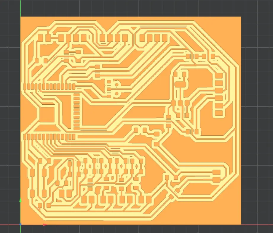
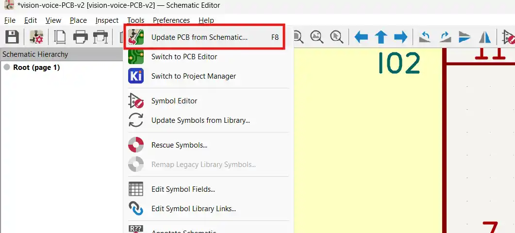
Then I pressed the update PCB from schematic button to transfer the schematic to the PCB layout.
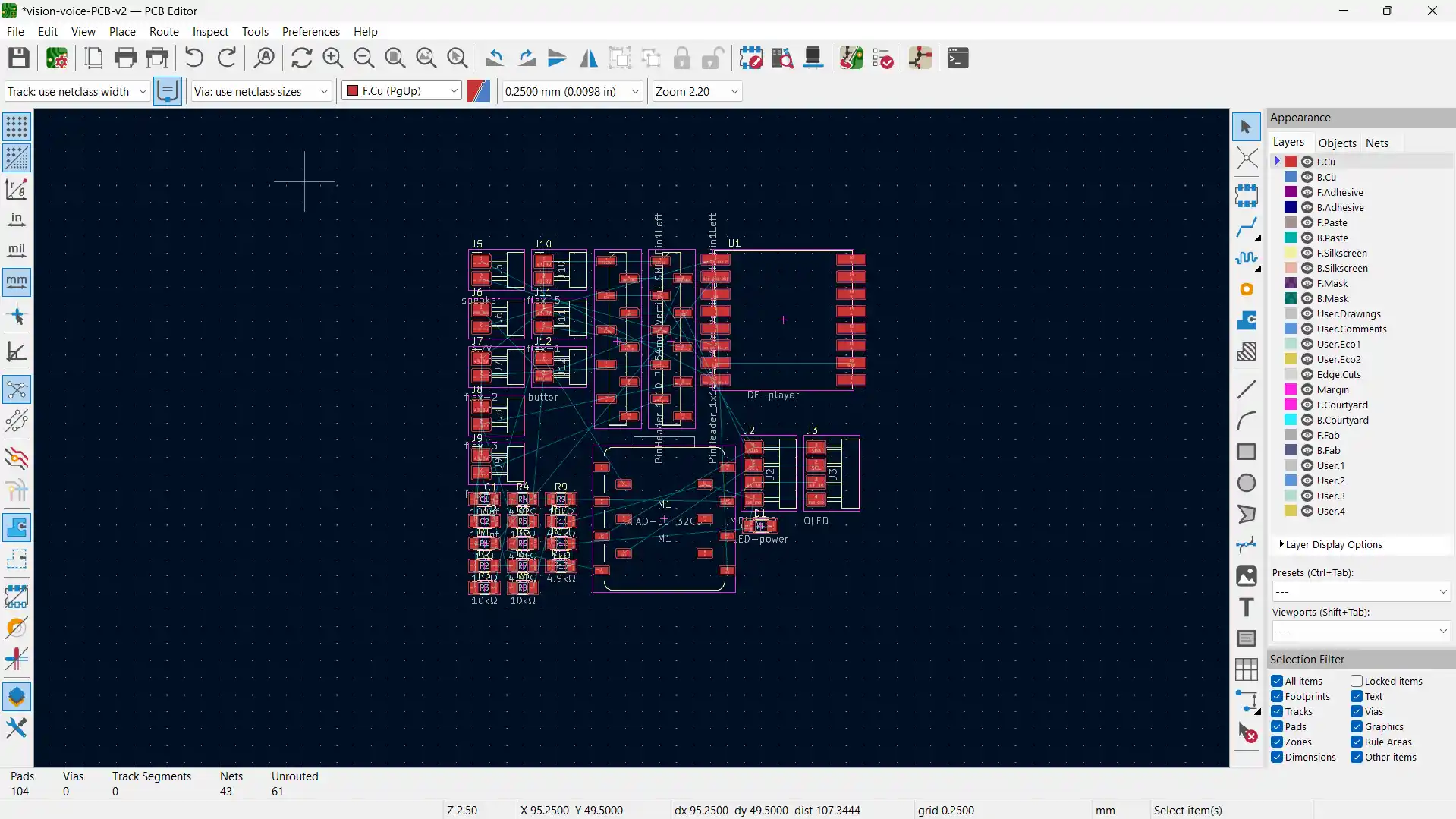
This is the unrouted PCB layout. As you can see, all the components are placed on the PCB but they are not connected yet.
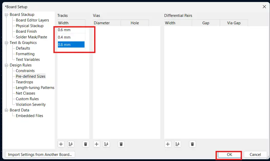
Before I started routing the PCB, I set up the trace sizes and here are the settings that I used:
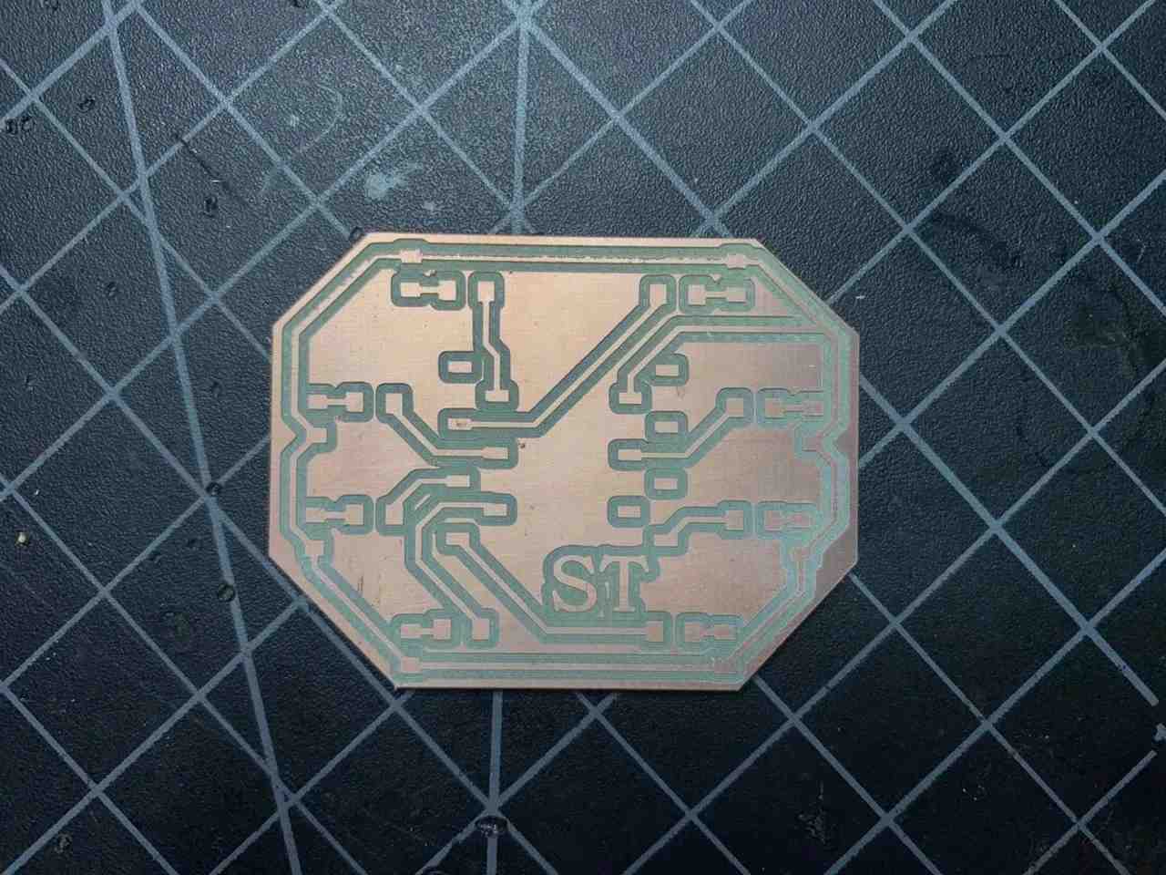
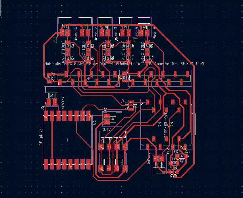
Then, after thoughtful minutes of routing, I finally got the PCB fully routed. FunFact!: I used ONLY 1 zero-ohm resistor and I feel so proud of myself for that!
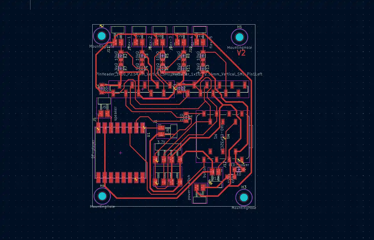
And here is the finished PCB design with the edge cut:
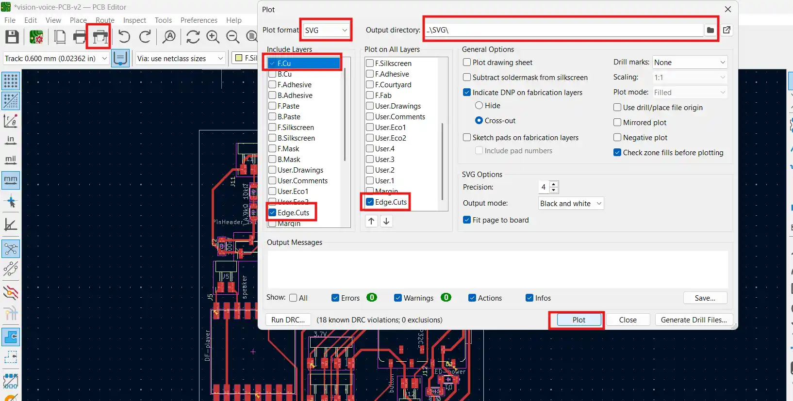
After that I exported the PCB design as an SVG file and here are the settings I used:
I then imported the SVG file to Inkscape to improve the quality (DPI) and to separate the interior and edge cut files.
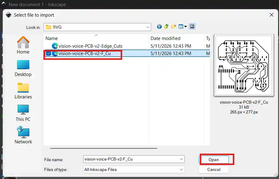
Here are the settings I used for the export in Inkscape:

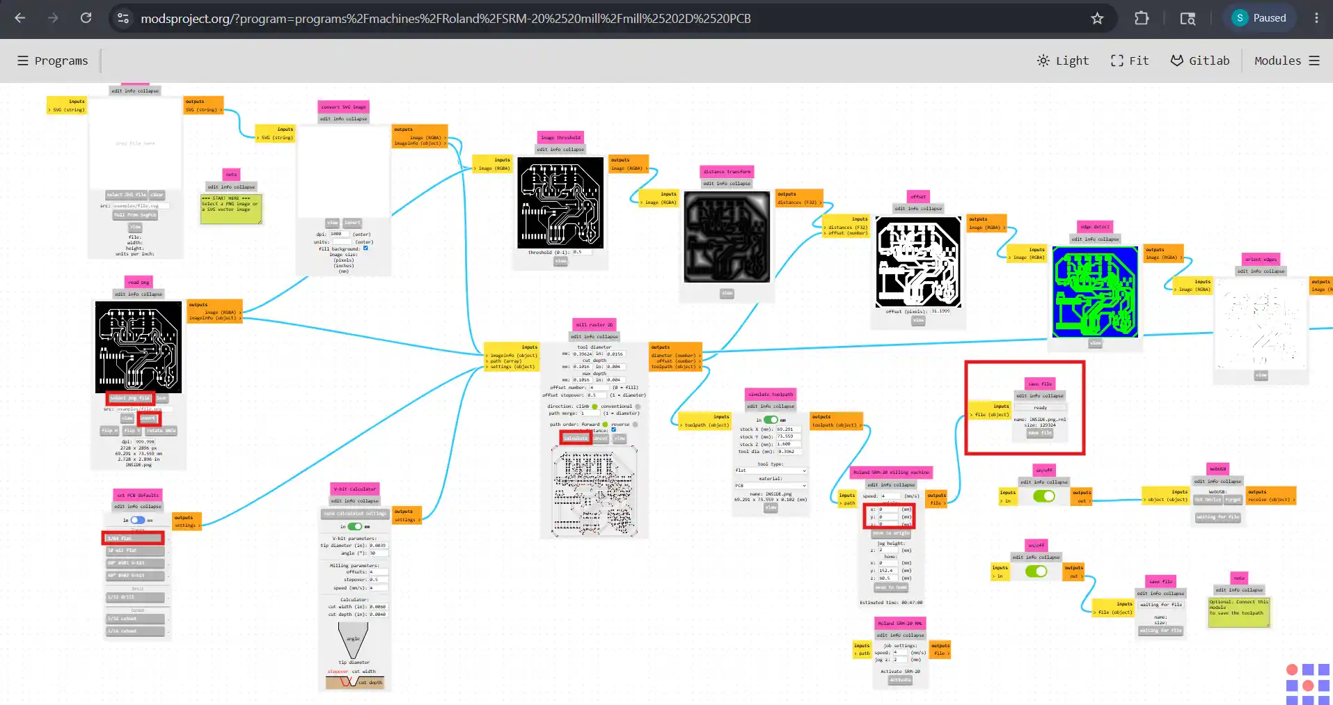
Using the Mods CE software, I generated the RML toolpaths for milling the PCB on the Roland SRM-20. Here are the settings I used for the Mods CE. For more detailed documentation on the PCB design and production process, check the full Week 06 documentation.
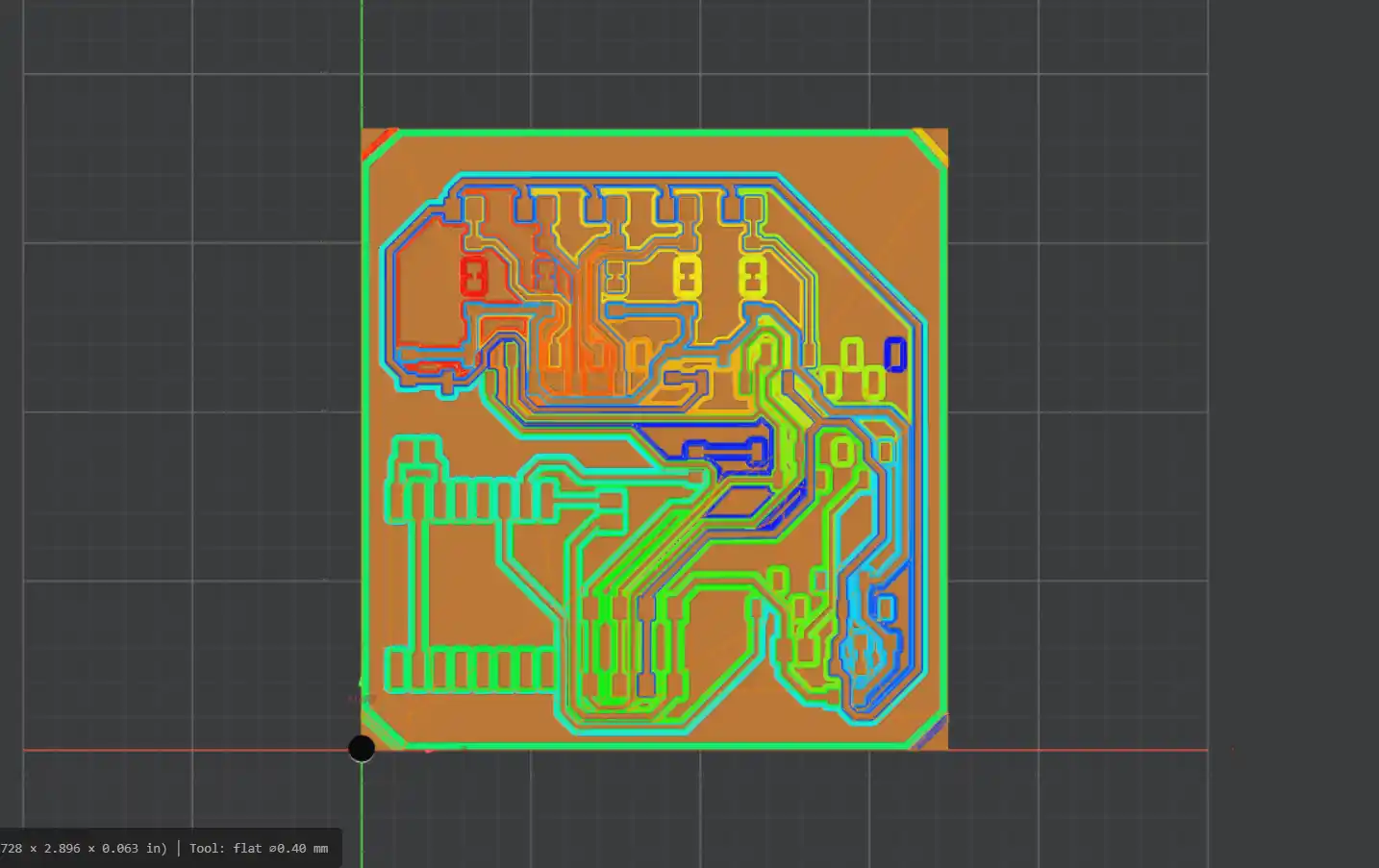
Here is the toolpath generated for the PCB:
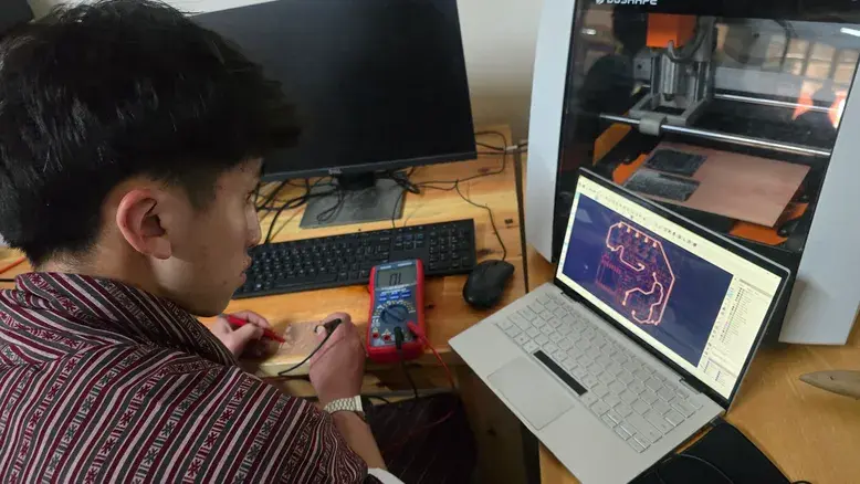
Then I turned on the Roland SRM-20, loaded the PCB material, and ran the toolpath to mill the PCB.
Right after milling the PCB, I cleaned it and, using a multimeter, I checked the continuity of the traces to make sure that they are properly connected and that there are no shorts.
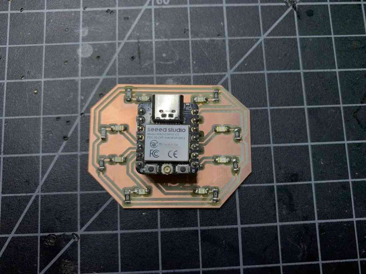
After milling the board, I soldered the trace pads and got ready for soldering the components.
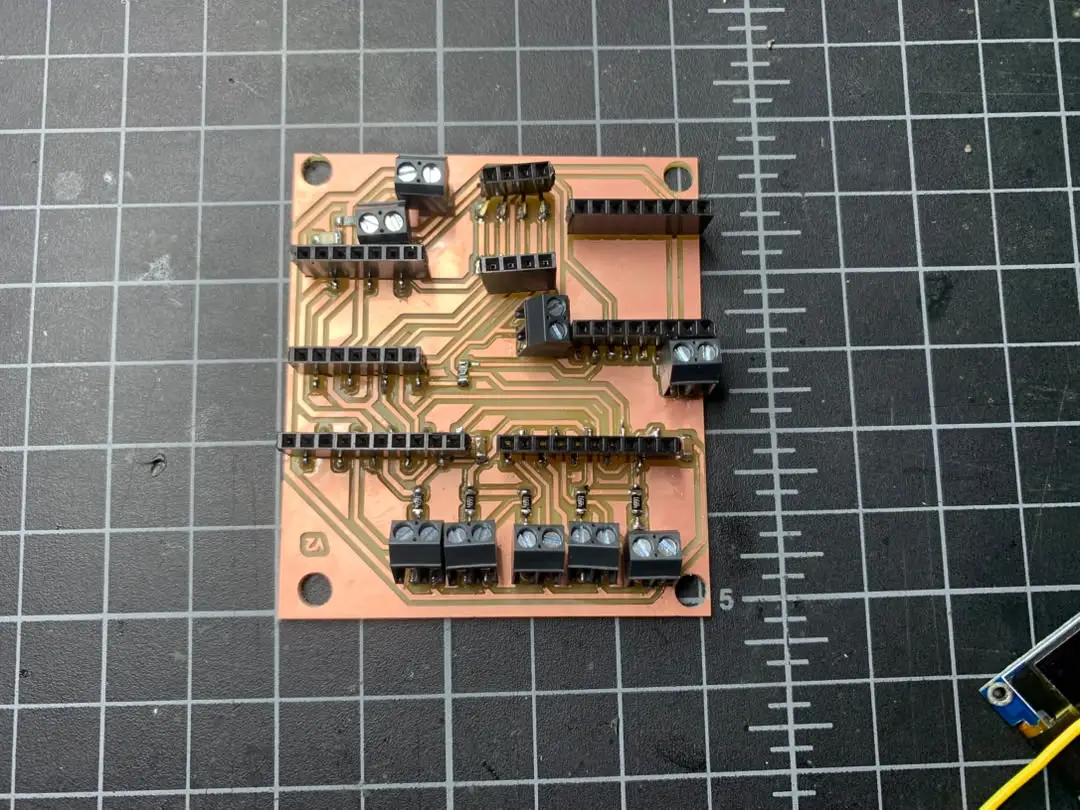
Here is the final board after soldering all the components:
ADS1115 Modules Arrive
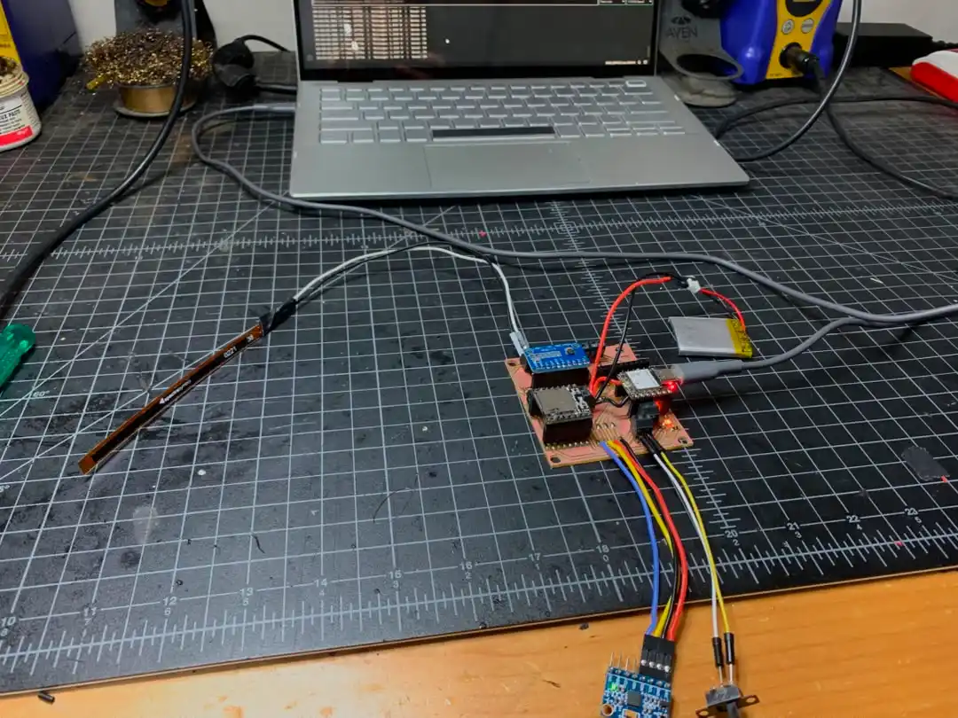
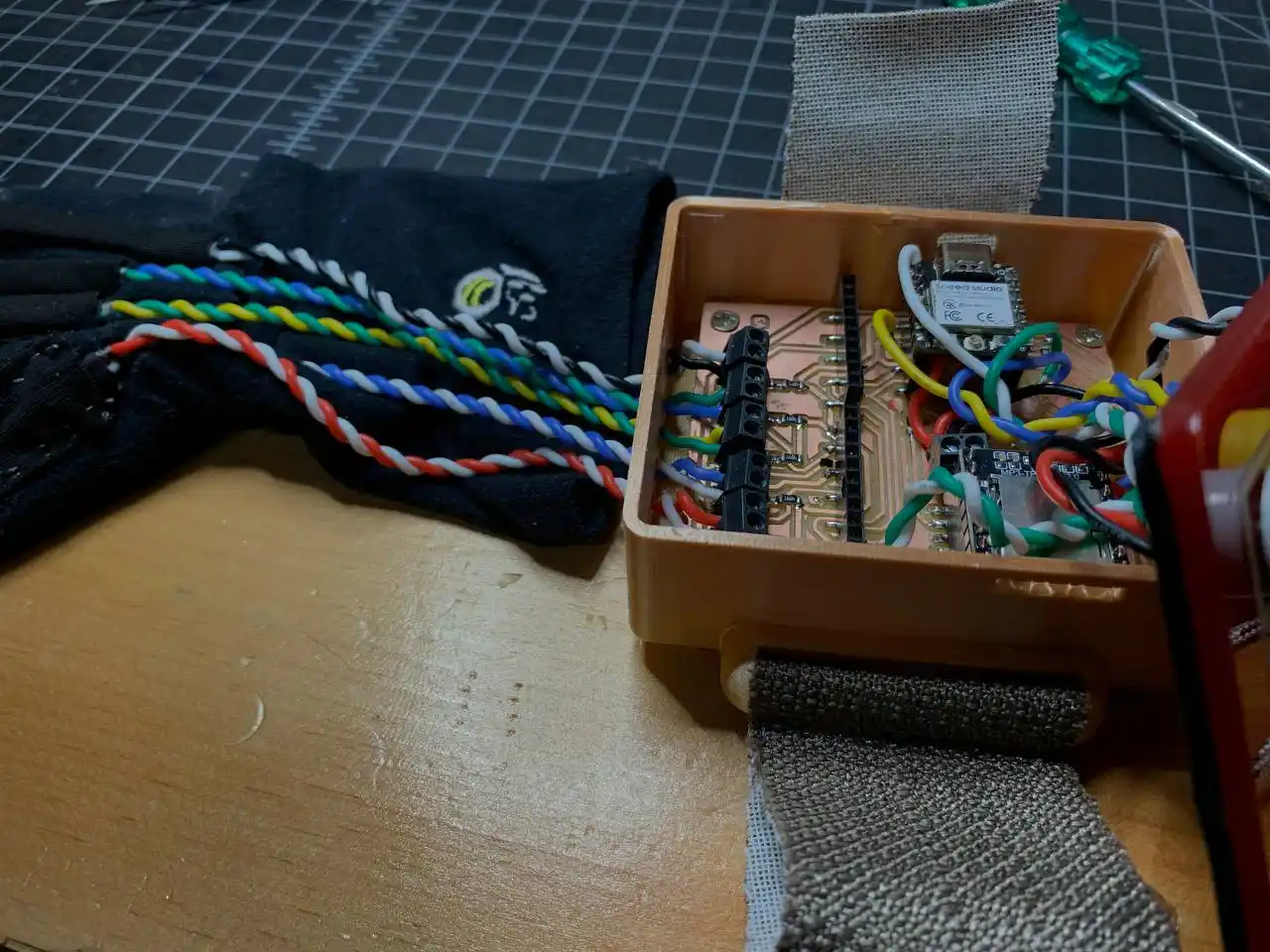
The ADS1115 modules arrived and I got them set up and working with the PCB I produced. I connected the ADS1115 modules to the I2C bus and made sure that they were working properly by reading the values from the flex sensors and displaying them on the serial monitor. Here is the setup of the PCB with the ADS1115 modules connected:
Here is the code that I used to test the ADS1115 modules with the flex sensors:
#include <Wire.h>
#include <Adafruit_ADS1X15.h>

Adafruit_ADS1115 ads1;

const int numSamples = 5;  // ← this is fine as a global constant

void setup() {
  Serial.begin(115200);
  Wire.begin(D4, D5);

  if (!ads1.begin(0x49)) {
    Serial.println("ADS1115 at 0x48 not found! Check wiring.");
    while (true);
  }

  ads1.setGain(GAIN_ONE);
  Serial.println("ADS1115 ready at 0x48");
  Serial.println("----------------------------------------");
}

void loop() {
 // mp4ing average
  long sum = 0;
  for (int i = 0; i < numSamples; i++) {
    sum += ads1.readADC_SingleEnded(0);
  }
  int16_t raw = sum / numSamples;

  float voltage = ads1.computeVolts(raw);

  Serial.print("Raw: ");
  Serial.print(raw);
  Serial.print("  |  Voltage: ");
  Serial.print(voltage, 3);
  Serial.print(" V");

  if (raw < 100) {
    Serial.print("  ⚠ Near zero — check wiring!");
  } else {
    int bend = map(raw, 14850, 9100, 0, 100);
    bend = constrain(bend, 0, 100);
    Serial.print("  |  Bend: ");
    Serial.print(bend);
    Serial.print("%");
  }

  Serial.println();
  delay(200);
}
After testing the ADS1115 modules with one flex sensor, I connected all 5 flex sensors to both ADS1115 modules and tested them together. Here is the setup of the PCB with all 5 flex sensors connected to the ADS1115 modules:
For the code I used the same one as above.
Project Planning
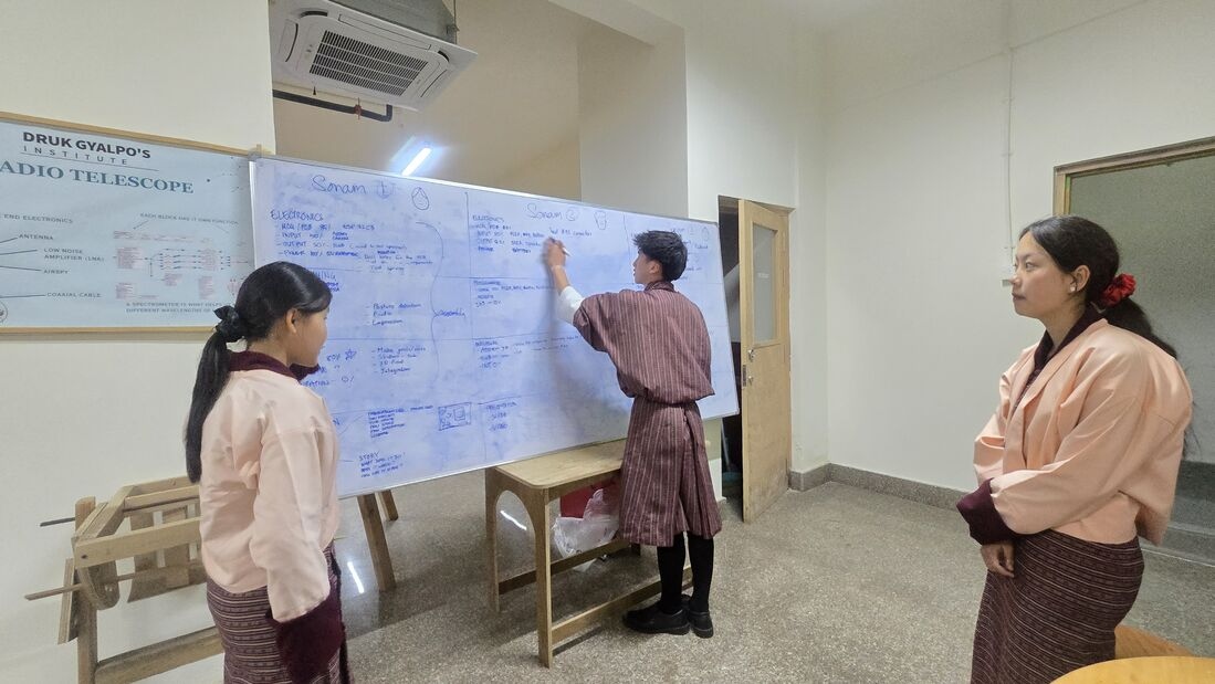
It's been some time since I last checked on what things are left to do for the project, so my two other friends and I, who are also working on our own projects, had a meeting to discuss our progress and to plan the next steps. We discussed the current state of the project, what we have accomplished so far, and what the next steps are that we need to take to complete the project. We also discussed any challenges that we were facing and how we could overcome them.
Final Enclosure Design
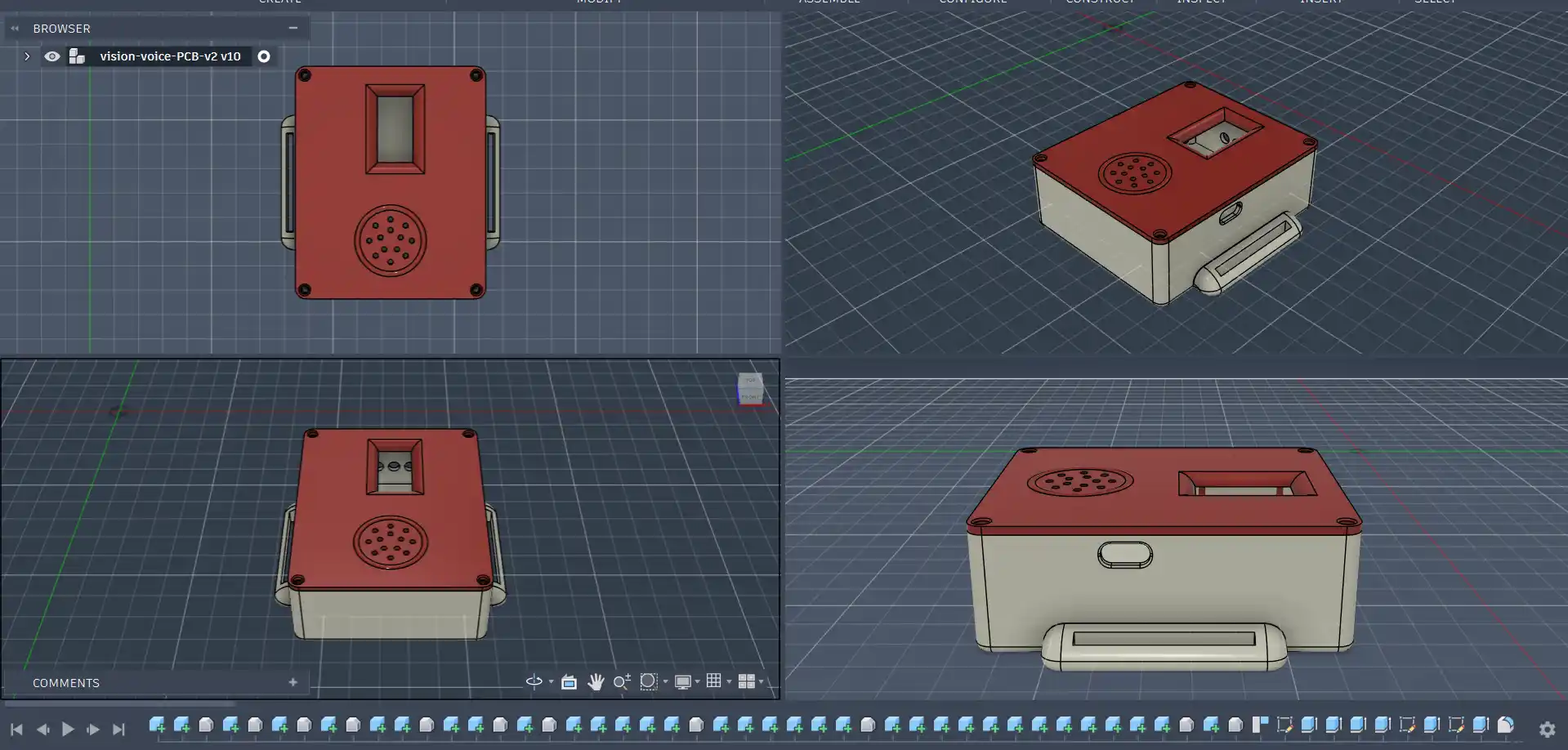
After testing all the components together and confirming that they were working properly, I started designing the final enclosure for the glove. I used Fusion 360 to design the enclosure and I made sure that it is compact and can fit all the components inside it. I also made sure that the enclosure has enough ventilation for the components to prevent overheating.
Here is the final enclosure design that I came up with:
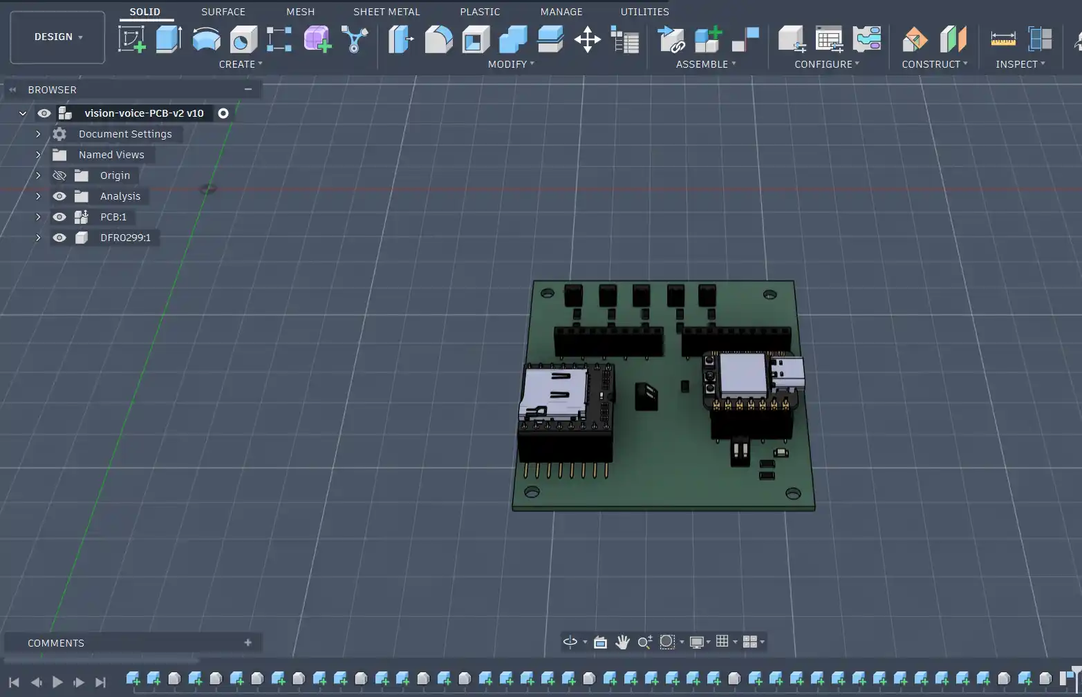
First, I started with exporting the STEP file of the PCB model. To get the STEP file, in KiCad I used the export as model tool to export the PCB design as a STEP file. Here are the settings I used for the export:

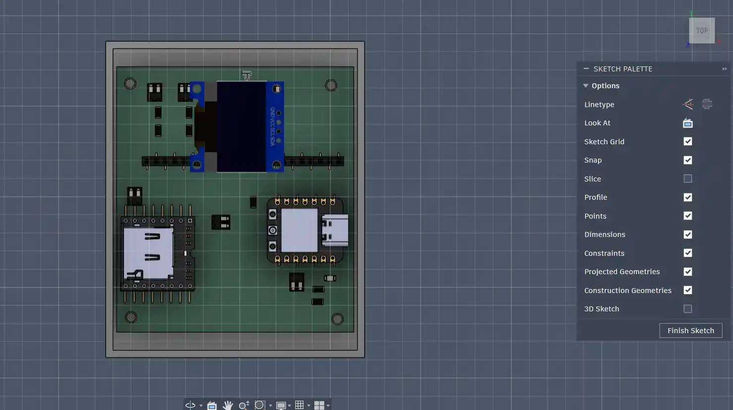
Then I imported the STEP file into Fusion 360 and here is the PCB model:
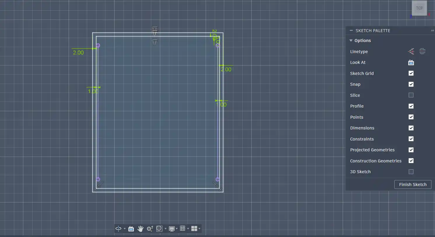
After getting the PCB model, I sketched the base of the enclosure:
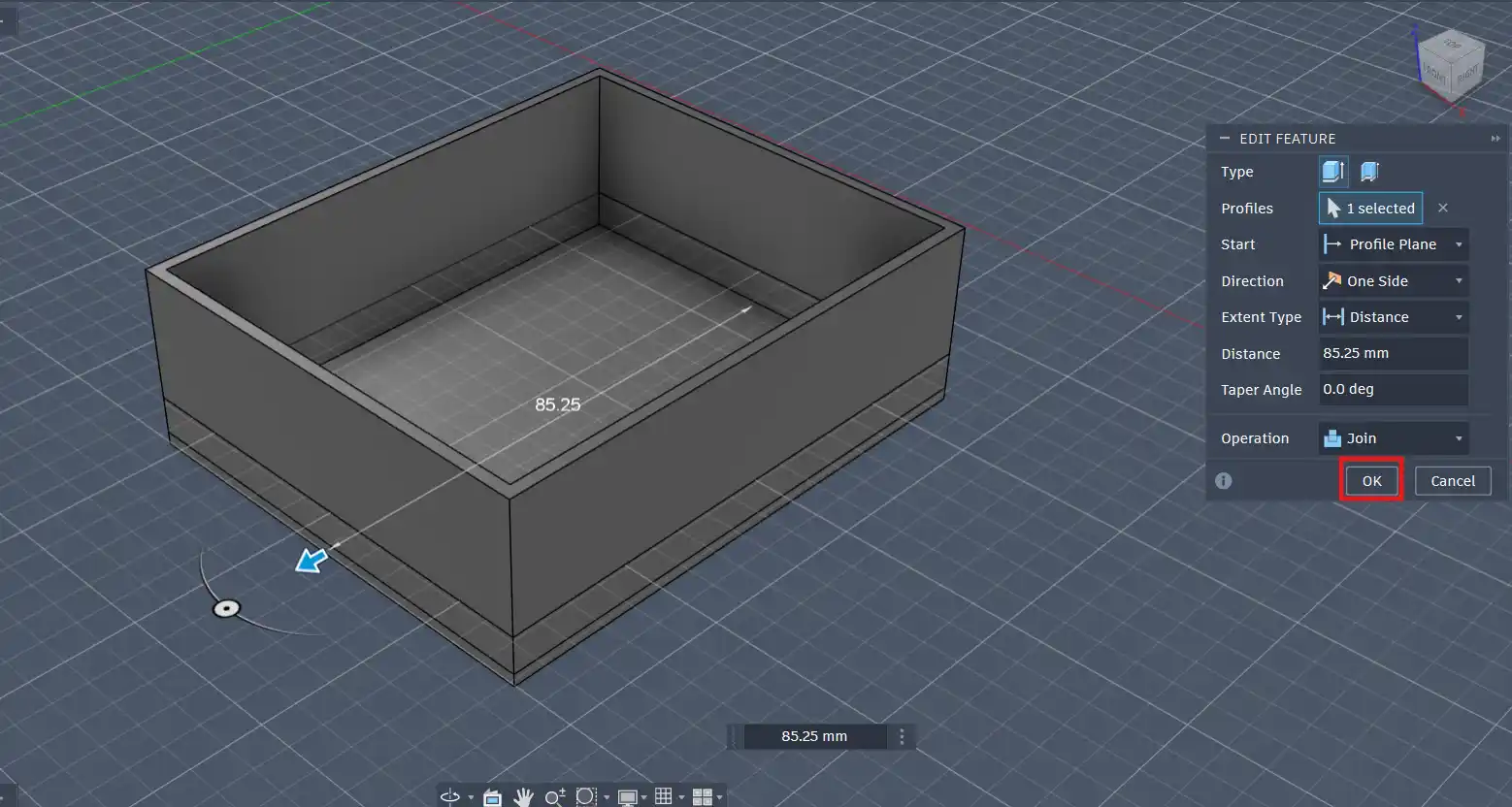
Then, using the extrude tool, I extruded the base to give it thickness:
I then made circles for the screws for the PCB to be attached to the enclosure like this:
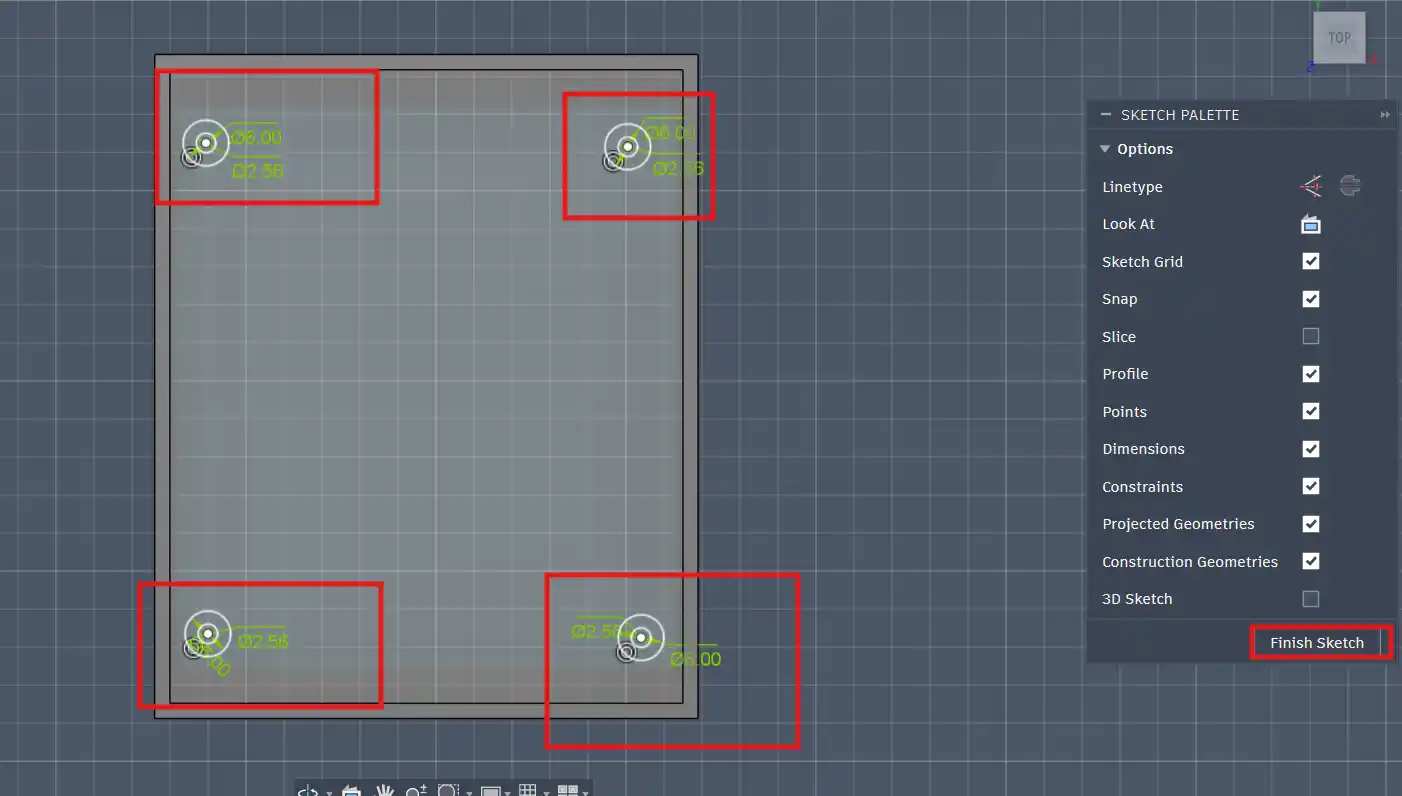
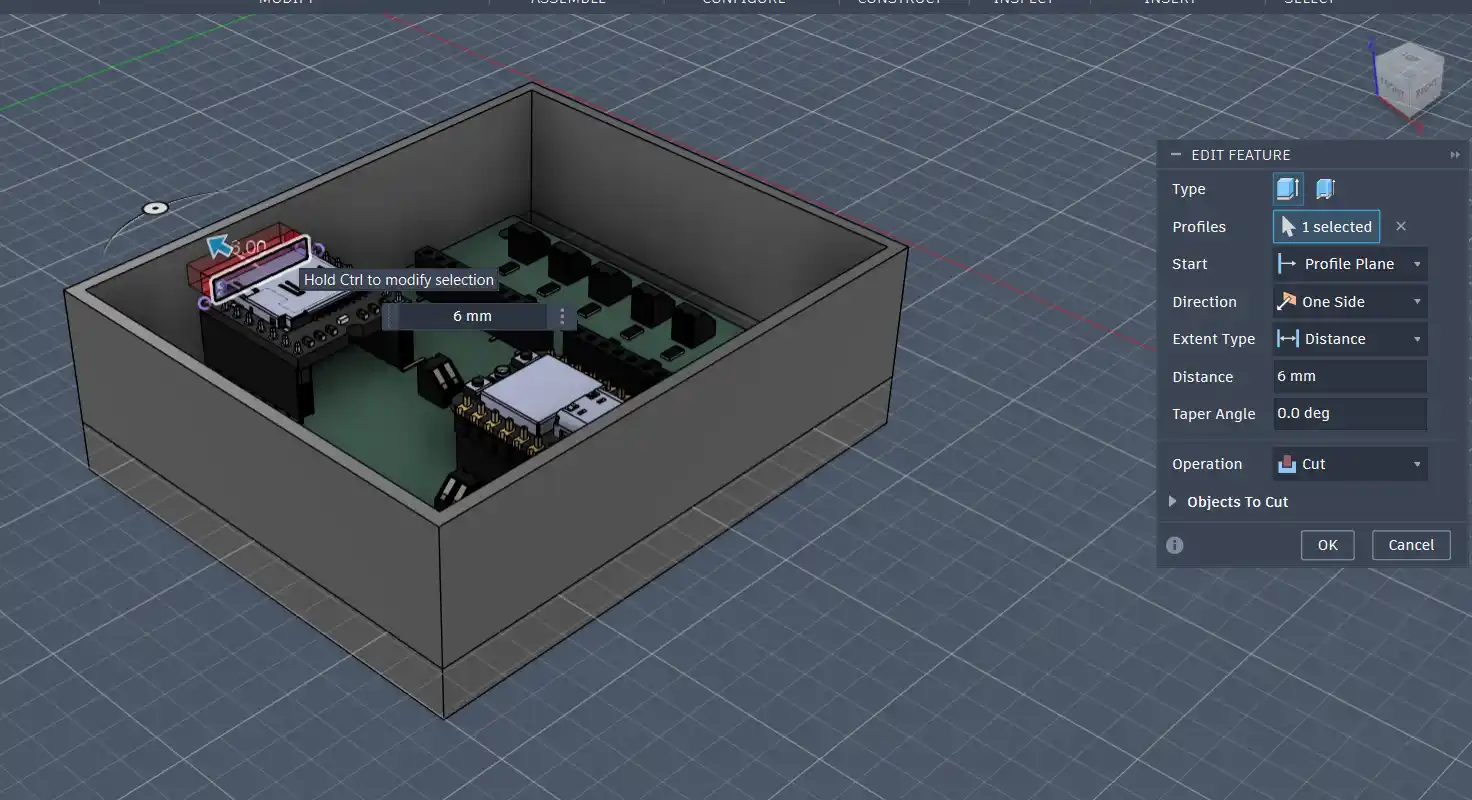
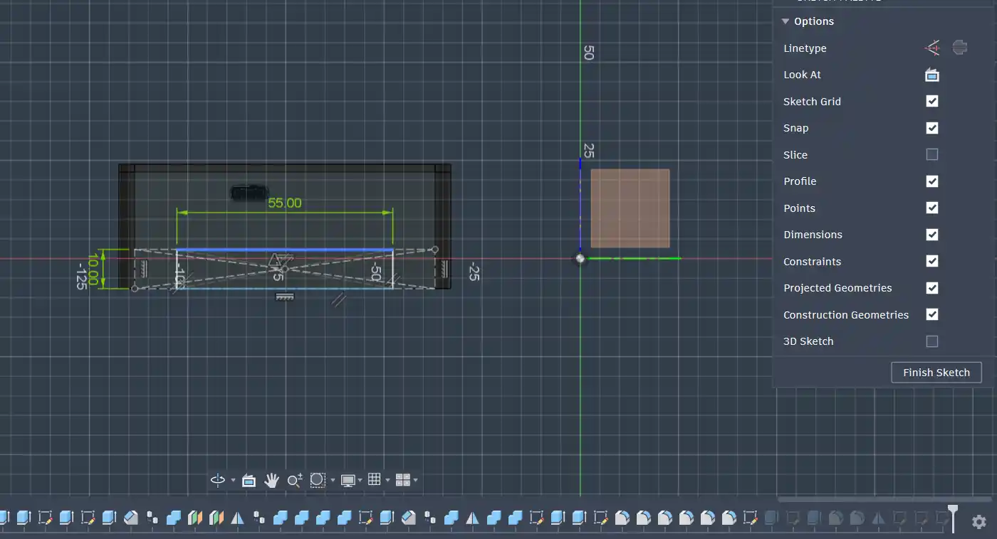
Then I used the extrude tool to extrude the holes for the screws. After that I made 2 sketches for the slot of the SD card and the hole for the USB-C cable:
After making the sketches, I extruded the holes for the SD card and the USB-C cable:
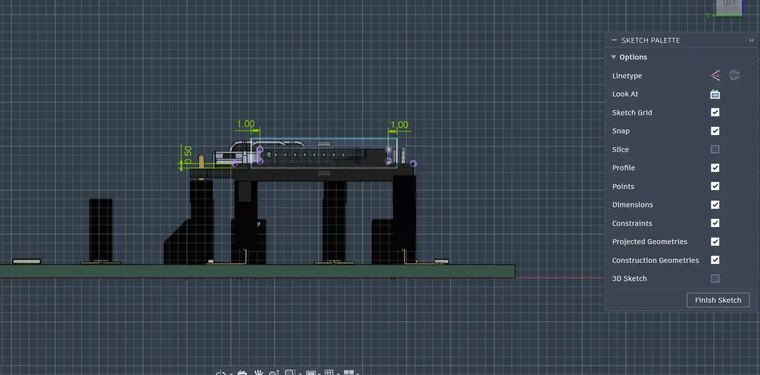
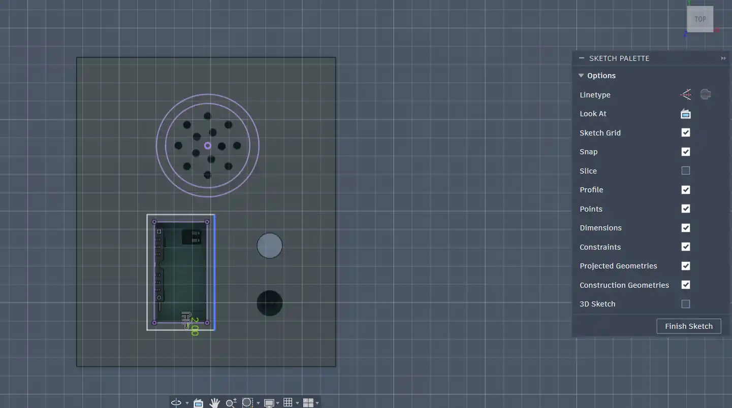
I then placed the OLED and the speaker on top of the lid and sketched holes for them.
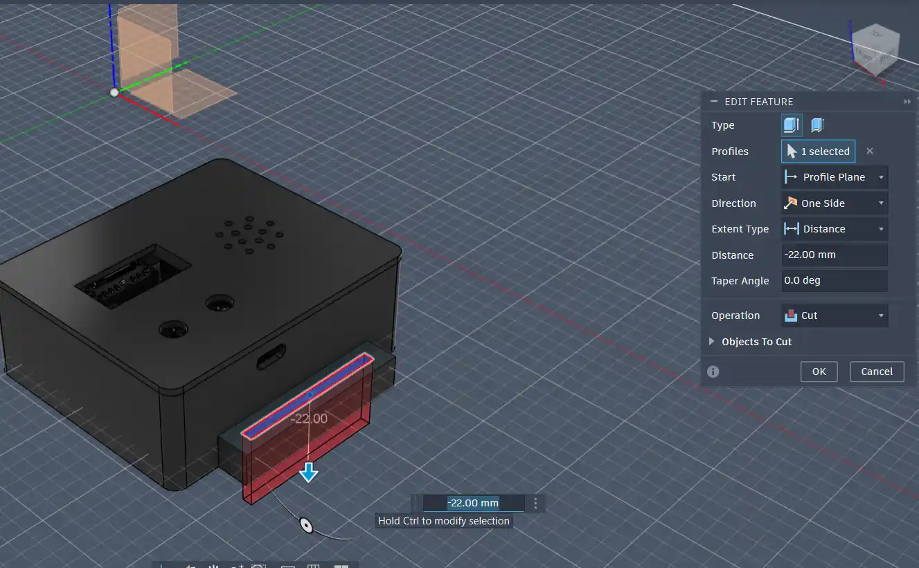
Then for the handles, I sketched rectangles on the sides of the enclosure and extruded them to give them thickness:
After that I again used the extrude tool to cut the holes for the handles:
Finally, I added fillets to the edges of the enclosure to give it a smoother look:
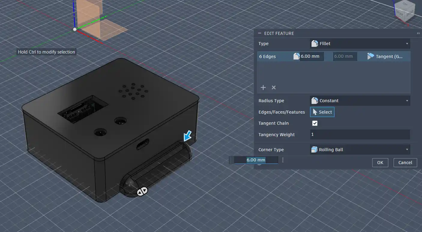
Here is the final enclosure design again:
After that, using the Prusa Slicer, I made the G-code of the design and got into printing the model.
This is the final printed enclosure:
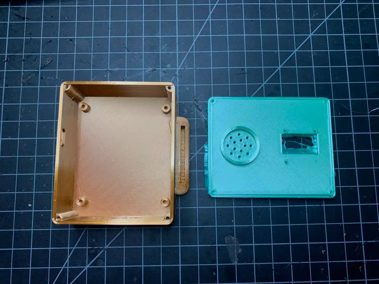
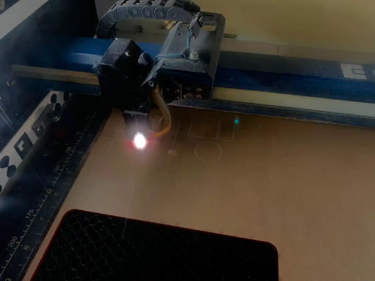
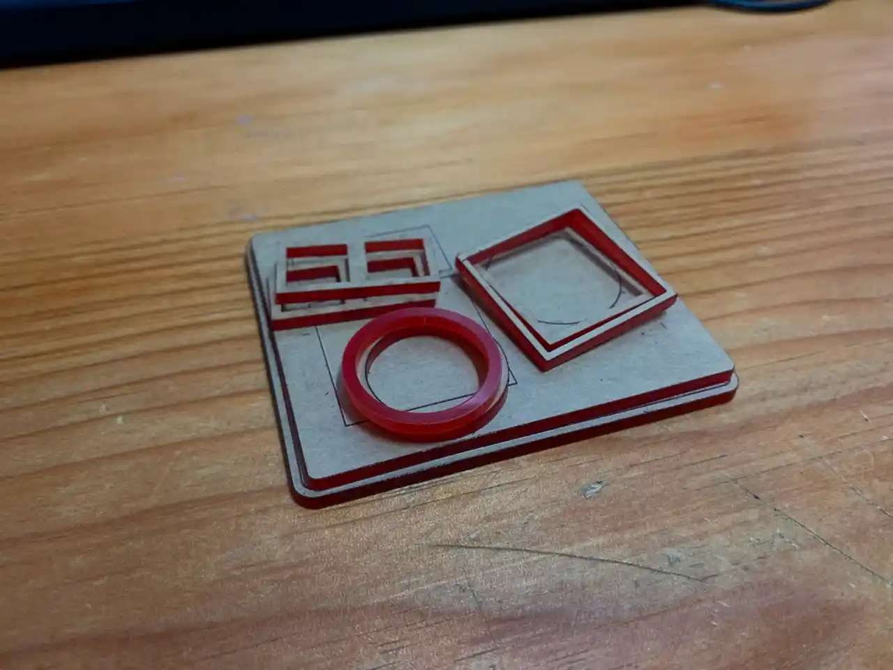
I wanted the lid to be a bit tight and it was also thin, so I switched to making the lid with a laser cutter. I used the sketches from the above design and laser cut the lid on acrylic and here is the result:
1st Prototype Assembly and Testing
I assembled the first prototype of the glove using the PCB that I milled and soldered, the enclosure that I designed and printed, and all the components that I tested together. I made sure to connect everything properly and to test the functionality of the glove after assembling it.
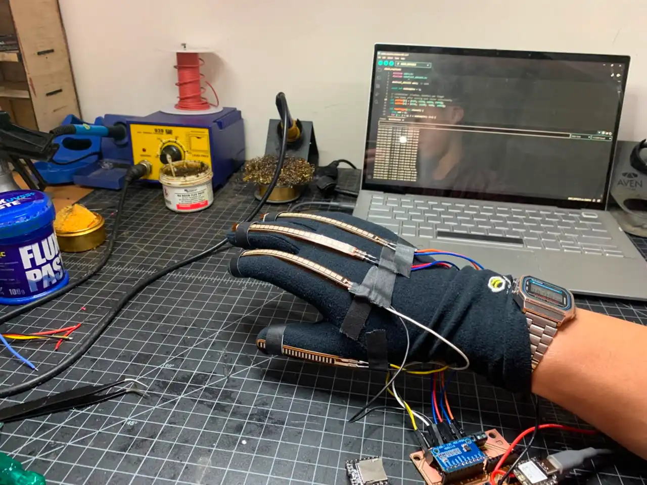
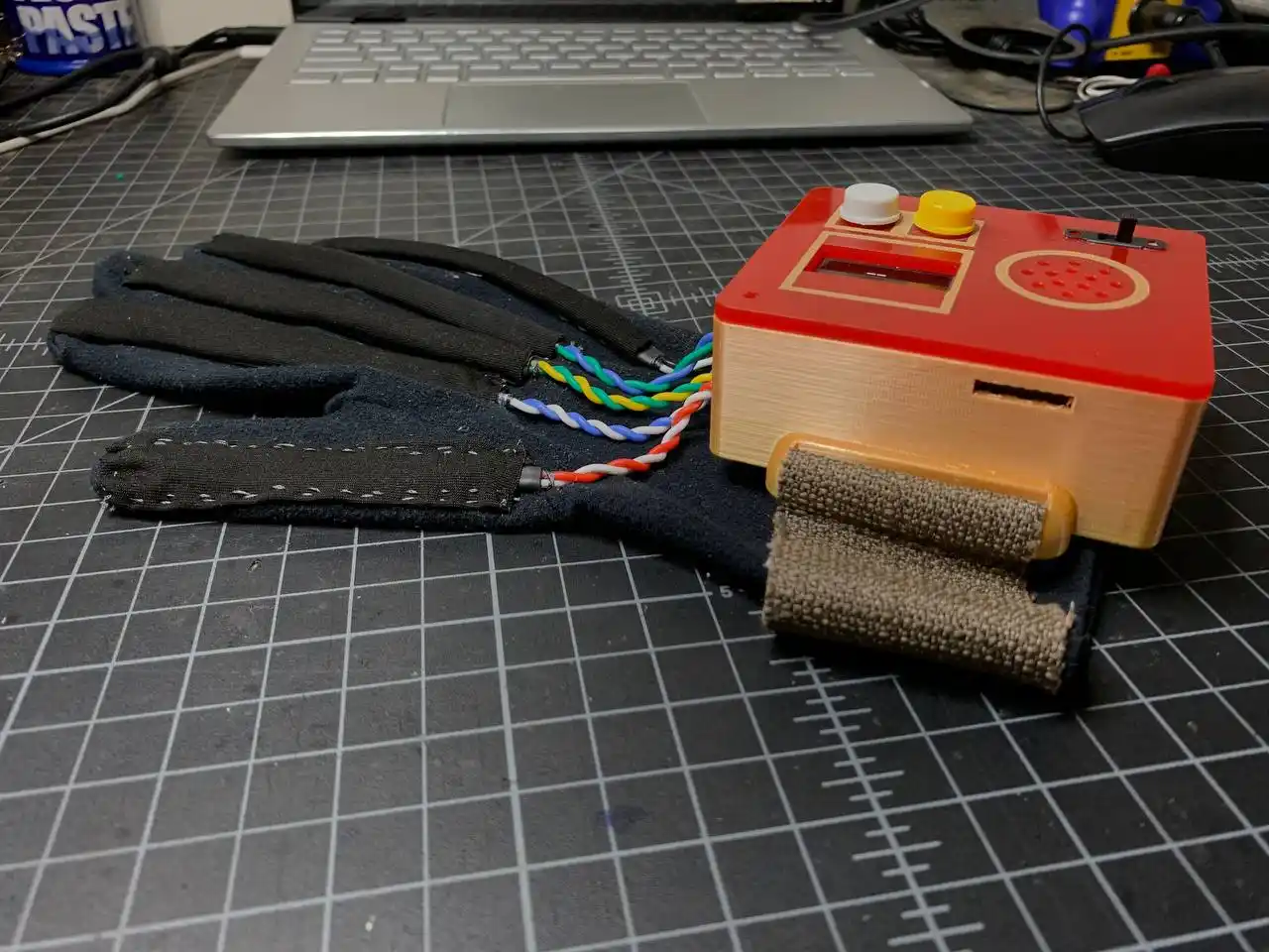
Here is the first prototype of the glove:
I was able to capture and sign some of the ASL gestures, but the wires from the flex sensors looked a bit messy and I also needed to sew the flex sensors to the glove and make a wristband for the enclosure to be able to wear the glove.
Sewing the Flex Sensors and Making a Wristband
After the first prototype assembly and testing, I realized there were some improvements that I needed to make to the glove, so below are the changes that I made:
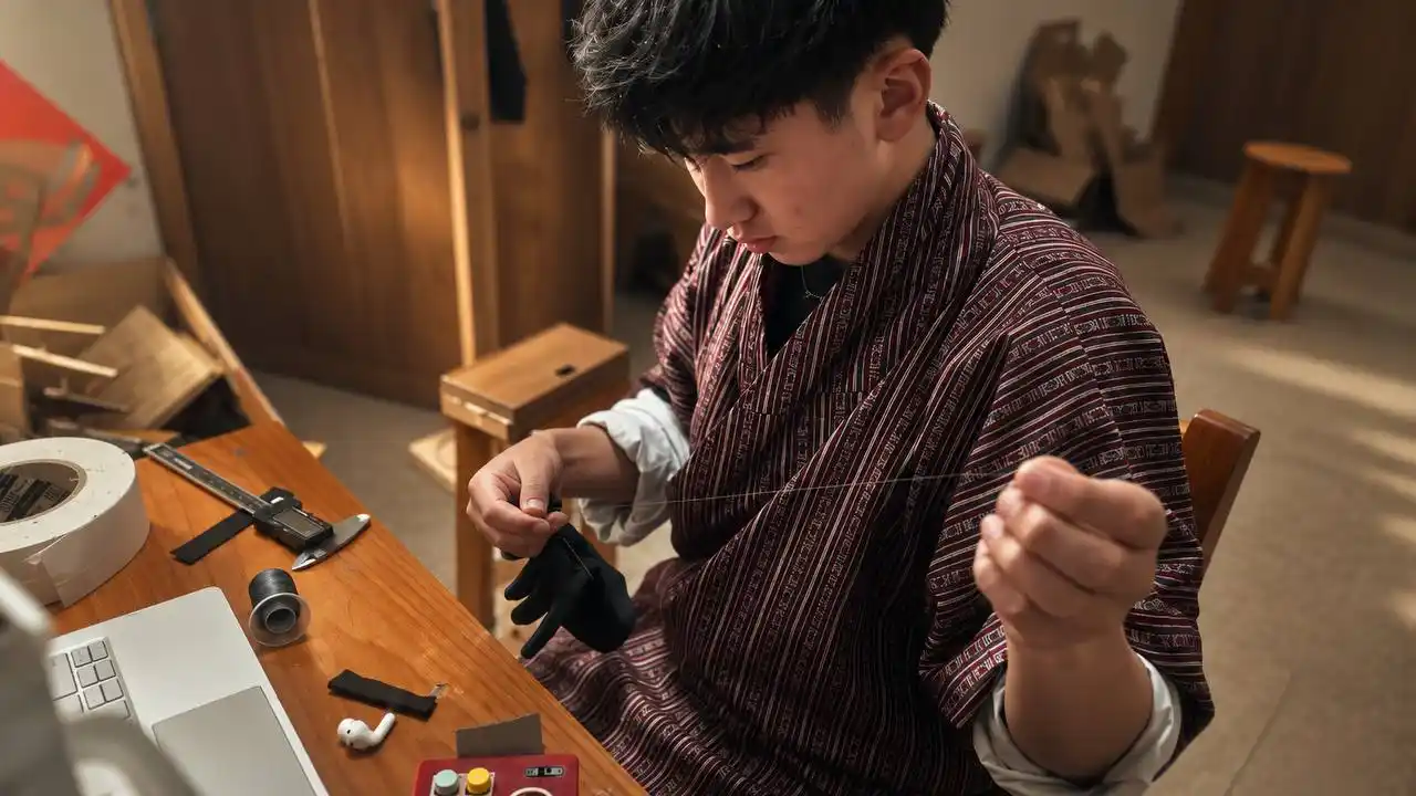
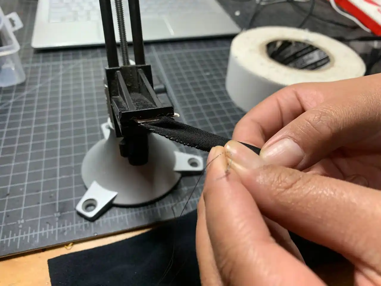
Firstly I sewed the flex sensors to the glove to make sure that they were properly attached. While sewing, I had a lot of fun finding the needle hole ^_^.
I also made sure to make the slots for the flex sensors.
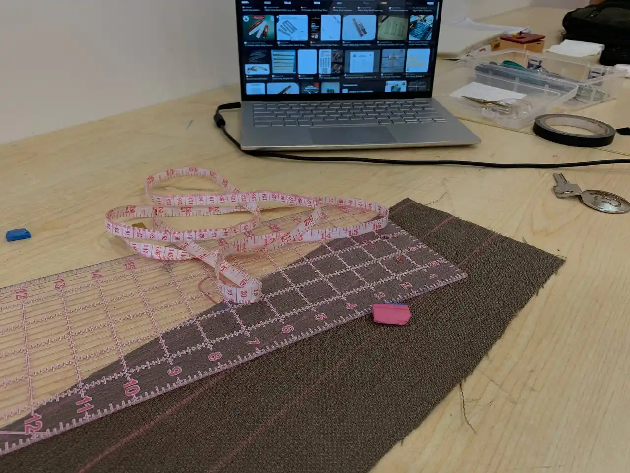
After sewing the slots for the flex sensors, I started to measure and cut the fabric for the wristband. ^_^ I had a very hard time figuring out how to make the wristband adjustable as I didn't have any idea about making it adjustable.
But after some research, I found out that I could use Velcro to make it adjustable.
I carefully sewed the band to the enclosure and made sure that it was securely attached, but I soon realized that the band was not able to adjust, so I cut the band, redesigned it, and sewed it again to make it adjustable using Velcro.
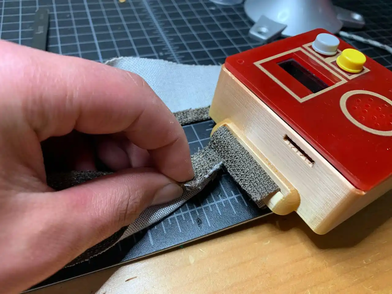
Here is the final design of the wristband after making it adjustable using Velcro:
Taking Care of the Flex Wires! ^_^
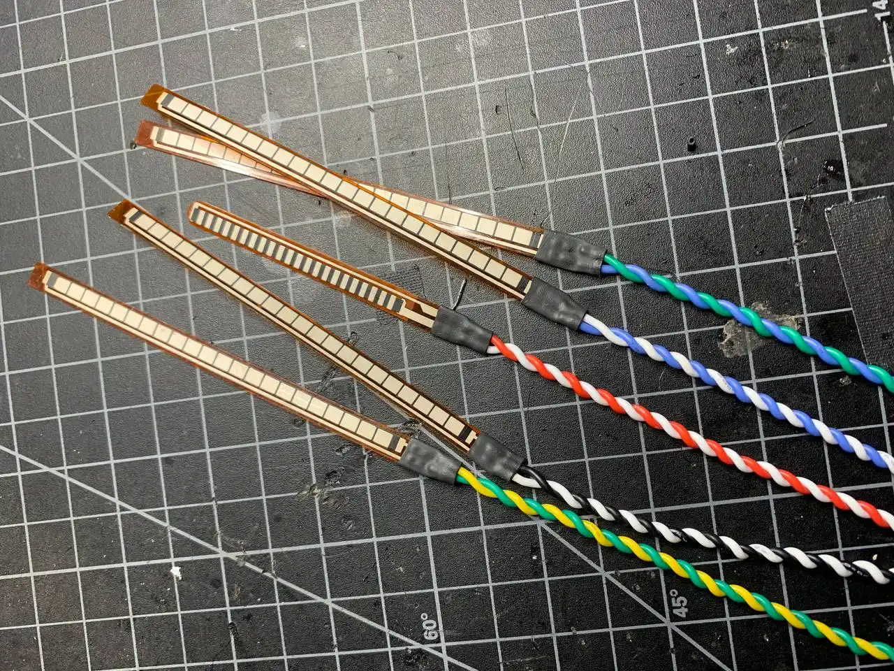
After sewing the slots and the wristband, I used silicone-insulated wires for the flex sensors to make sure that they were flexible and neatly braided.
Here are the flex sensors after making the wires neat and flexible:
After that I connected the flex sensors to the PCB and made sure that everything was working properly.
I found a problem in the programming, as while capturing the letters it was taking a lot of time, so I had to change the code to make it faster - I have put all the versions of programs that I used for the glove at the end of this documentation.
Final Prototype Assembly and Testing
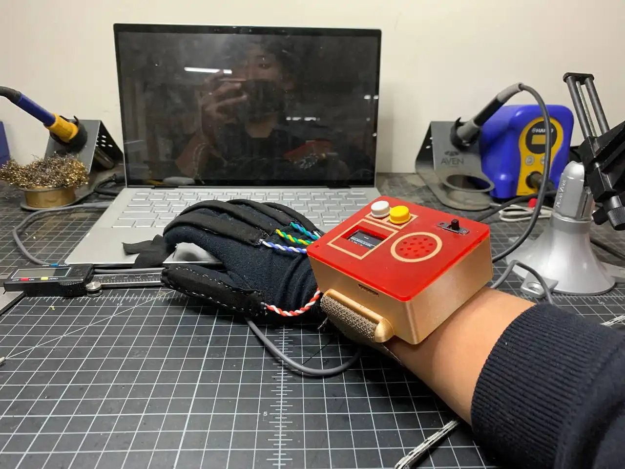
After beautifying the glove, here is the final result:
I'm really happy with how the glove turned out. It looks really neat and the wires are not messy at all. I then tested the glove and I was able to capture and sign some letters.
Here is the video of the testing:
Surprise!! I was able to sign "ILY" which is a common expression in ASL that stands for "I Love You". It's a combination of the letters I, L, and Y.
The glove looked really good and below are some photos of the glove:
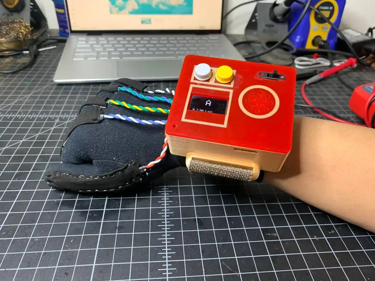 -photo of the glove signing the letter "A"
I was able to capture around 15 letters and I feel very happy with the result. Yayyy! :D
Reflecting on the Project Development Process
Building the Vision Voice glove was a really fun, challenging, and rewarding experience. Through the process of planning, designing, testing, and iterating on the glove, I learned a lot about electronics, programming, PCB design, and 3D modeling.
One of the biggest challenges I faced was sewing and designing the enclosure for the glove, as for the sewing I had no prior experience (I suffered a lot ^_^). For the enclosure design, I really struggled with making it compact enough to fit all the components inside it and also making it look good. But after a lot of trial and error, I was able to come up with a design that I am really happy with.
This project also taught me a lot about carefully planning, testing, and iterating on the design. I had to test each component individually before integrating them together, and even after integrating them, I had to make a lot of adjustments and improvements to get everything working properly.
Moreover, I had a lot of fun while building the glove as I was able to learn new skills and apply them in a creative way. I would rate this experience an 11/10 because it was really enjoyable and I am really proud of the final result. I am excited to continue working on this project and to see how it can be further improved and developed in the future.
^_^ I hope you enjoyed this project as much as I did.
Files for the Glove
Code for the Glove
Click here to access the code versions.
Enclosure Design
Click here to access the enclosure design.
Thank you for reading! See you next time! ^-^