2. Input Device with My PCB
2.2. Input Device - HC-SR04 Ultrasonic Sensor
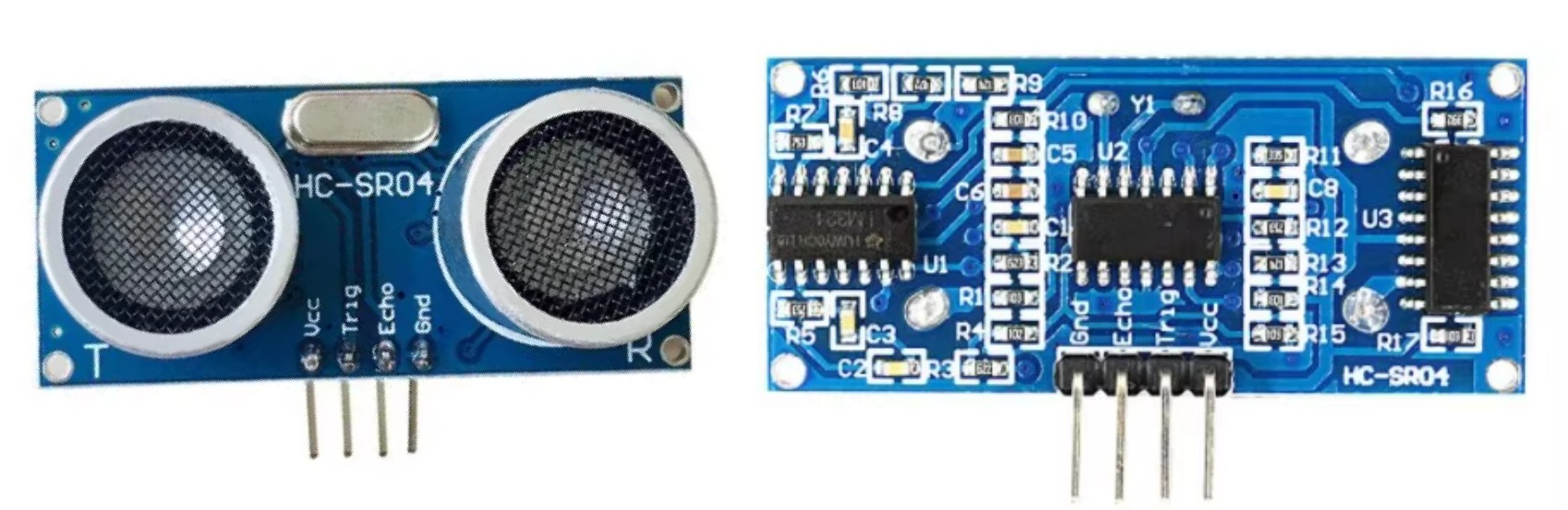
2.2.1 HC-SR04
The HC-SR04 Ultrasonic Distance Sensor is a widely-used, low-cost non-contact ranging module that measures distance by emitting ultrasonic waves.
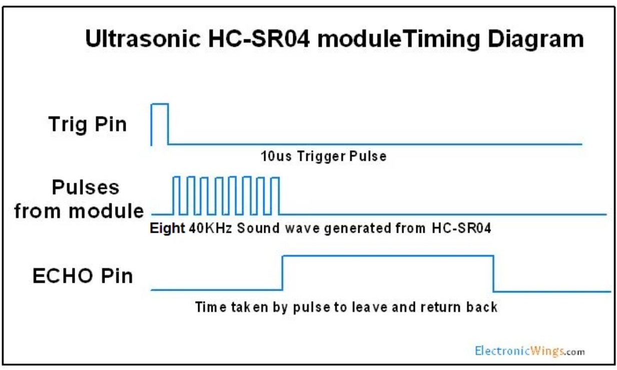
2.2.2 Working Principle
The HC-SR04 operates on time-of-flight (ToF) principle:
- Trigger: Send 10μs pulse to Trig pin → module emits 8 bursts of 40kHz ultrasonic waves
- Echo: Sound waves hit obstacle and reflect back → Echo pin outputs high-level pulse proportional to distance
- Calculate: Measure pulse duration, then apply formula:
Distance Formula: d = (t × 340) / 2
Where:
d= distance in meterst= time in seconds340= speed of sound in m/s
It is popular in robotics, automation, and DIY electronics projects for obstacle detection, distance measurement, and proximity sensing.
HC-SR04 Ultrasonic Sensor Guide
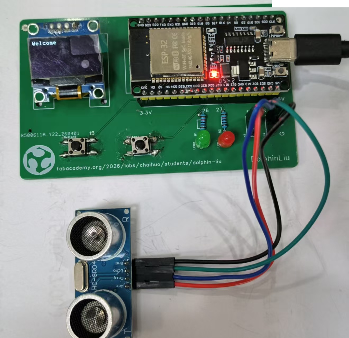
2.2.3 Connect HC-SR04 to my PCB.
I connect the 4pin HC-SR04 PCB pin header.
| SR04 Pin | ESP32 Pin | Function |
|---|---|---|
| GND | GND | Ground |
| VCC | 5V | Power Supply |
| Trig | GPIO18 | Trigger Input (10µs pulse to start measurement) |
| Echo | GPIO19 | Echo Output (pulse duration = distance) |
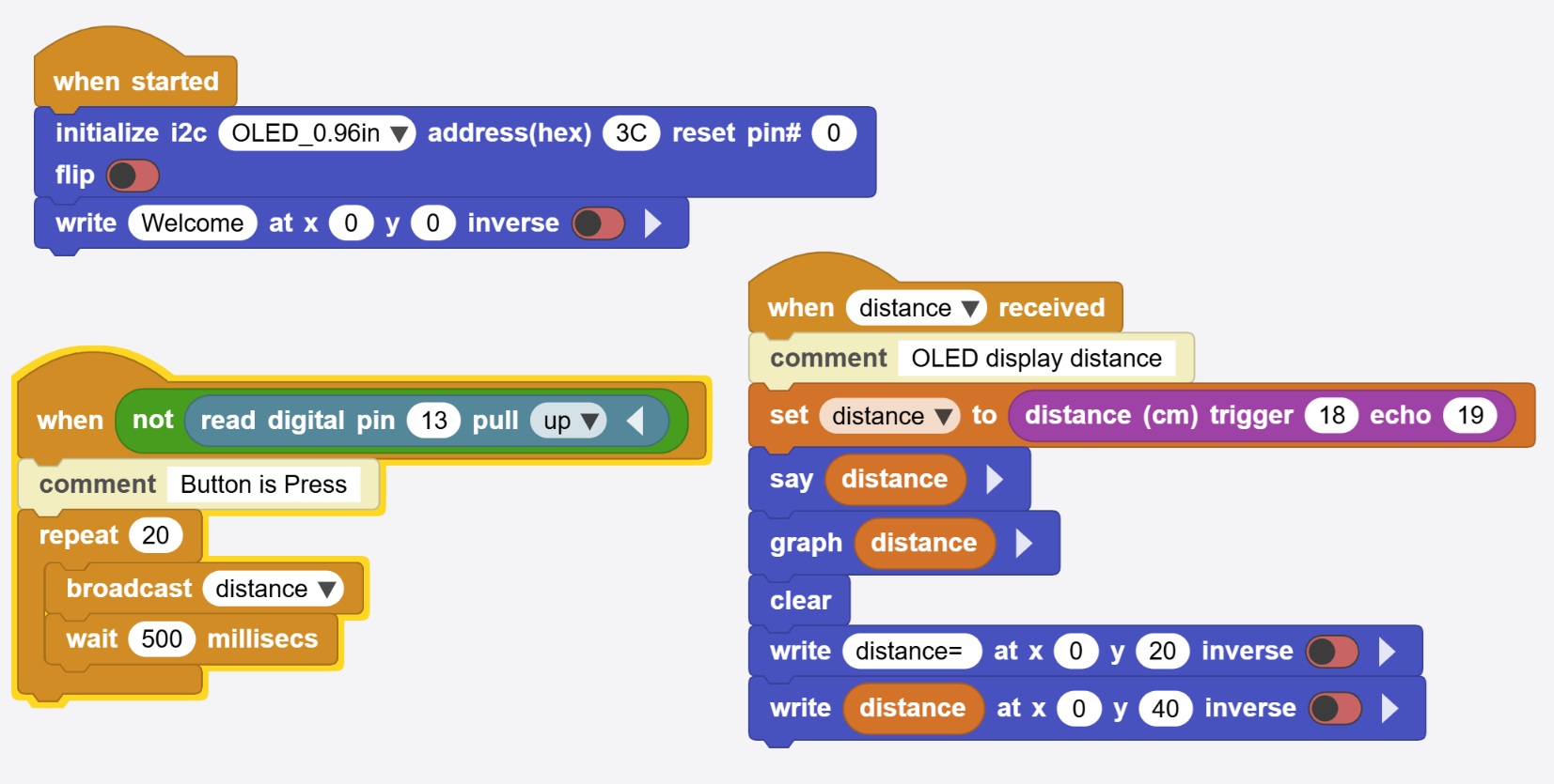
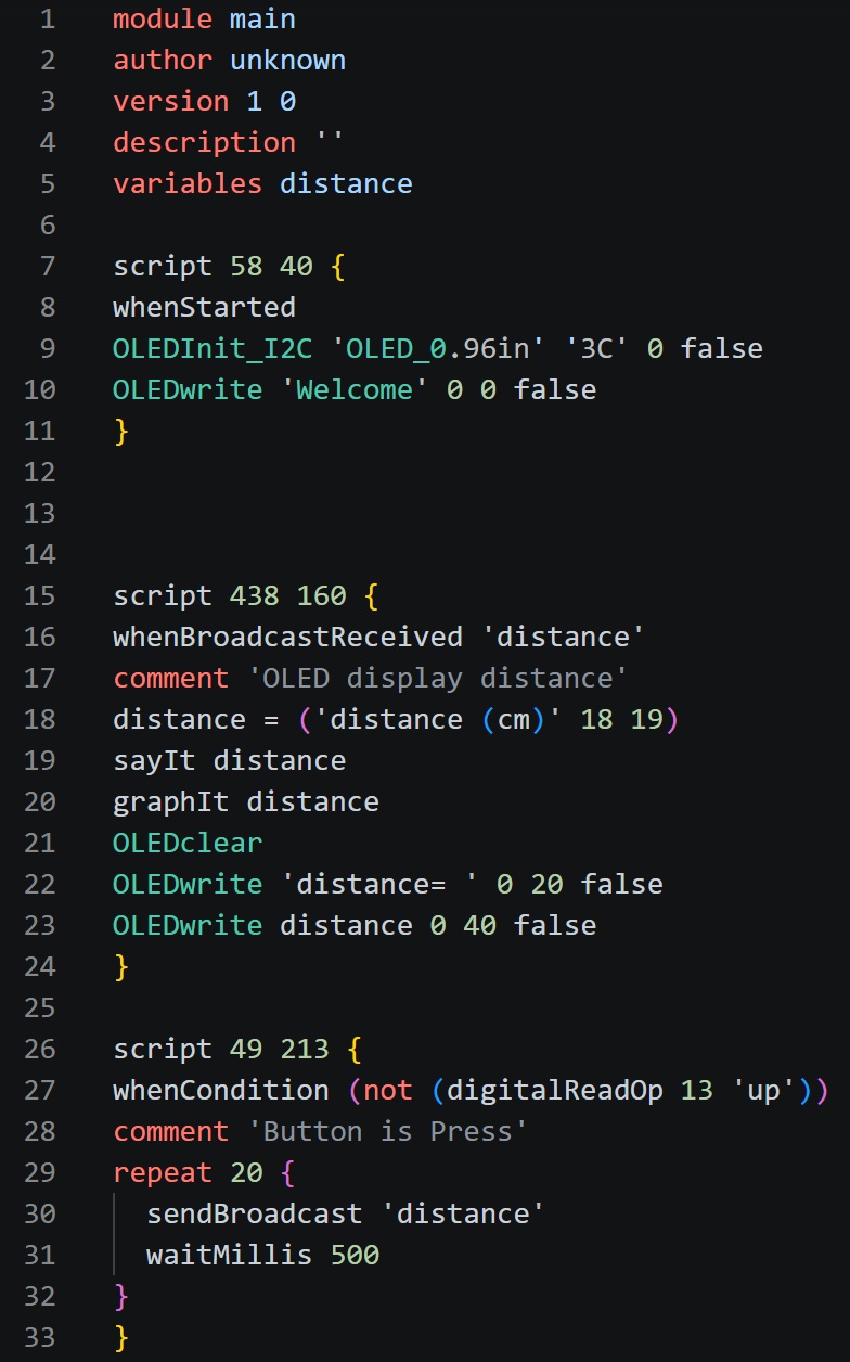
2.2.4 I write block code in MicroBlocks for quick testing.
I want to press button ,and the OLED can display the HC-SRC04 distance.
Here is the code:
 |  |
|---|
2.2.5 Testing
Here is the video of HC-SR04 testing. When I press the button, the distance will be displayed on the OLED. The distance is dependent on the distance between the paper and HC-SRC04.
I also record the vedio of the MicroBlocks Web IDE. I can review the distance number ,and the graph of the distance in MicroBlocks Web IDE.
2.3 Input Device - PIR Motion Sensor
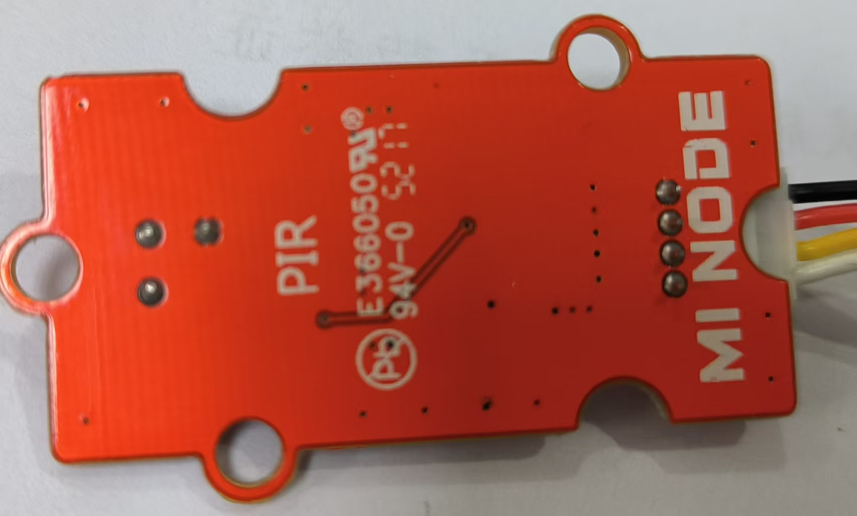
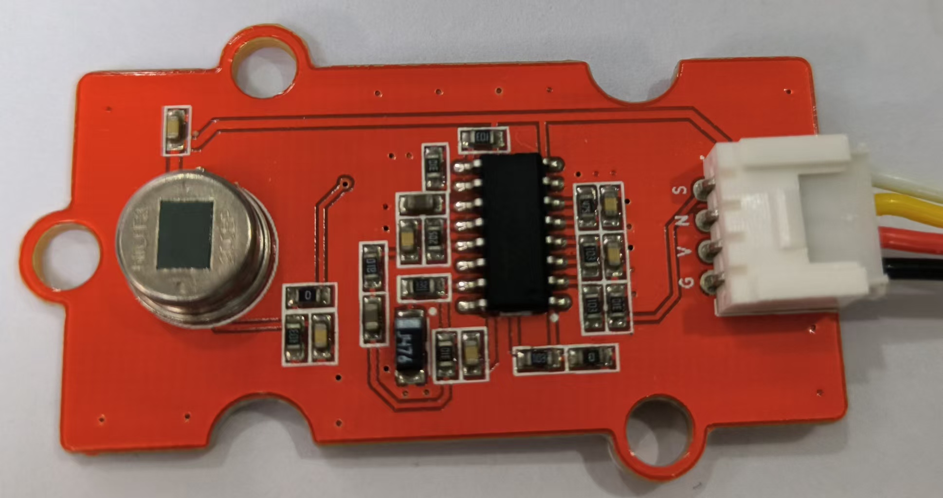
2.3.1 PIR
The PIR (Passive Infrared) Motion Sensor is a low-cost, low-power electronic module that detects motion by sensing changes in infrared radiation emitted by warm objects, such as humans or animals. It is widely used in security systems, automatic lighting, and smart home applications.
 |  |
|---|
2.3.2 Working Principle
The working principle behind a PIR sensor is relatively simple.
It detects infrared radiation emitted by warm objects (such as human bodies) in its field of view.
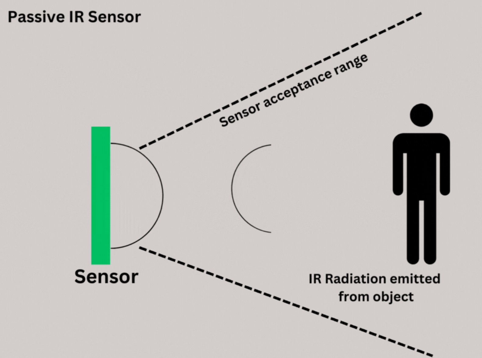 When a person or animal moves across the sensor’s detection area, the sensor notices a change in the amount of infrared radiation and triggers an output signal, typically activating a connected system, like an alarm or lighting system.
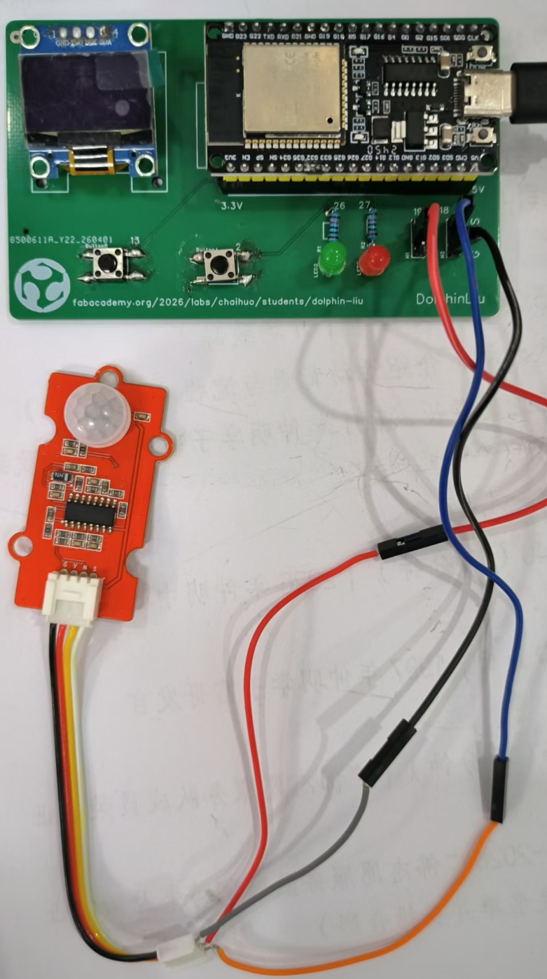
2.3.3 Connect PIR to my PCB.
I connect the PIR to PCB pin header.
| PIR Pin | ESP32 Pin | Function |
|---|---|---|
| GND | GND | Ground |
| VCC | 5V | Power Supply |
| N/C | — | No Connection (Not Used) |
| S | GPIO18 | Signal Output (Digital HIGH/LOW) |
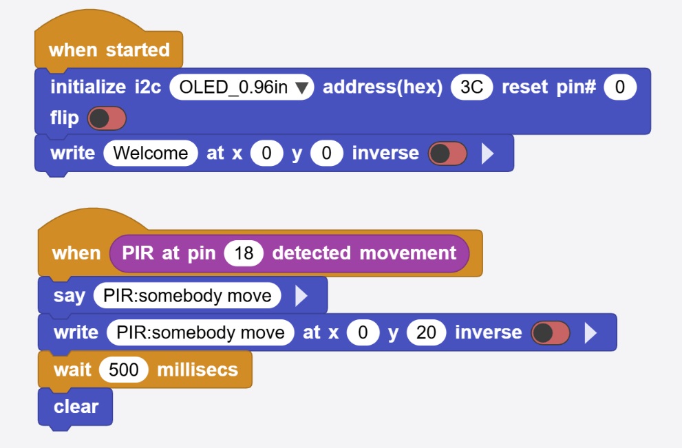
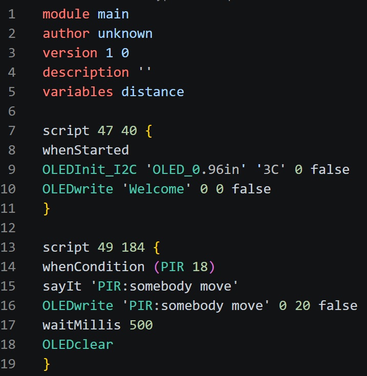
2.3.4 I write block code in MicroBlocks for quick testing.
I want the OLED display status if PIR check somebody move.
Here is the code:
 |  |
|---|
2.3.5 Testing
Here is the video of PIR testing.
2.4. Input Device - 3Pin Switch
2.4.1 Here is the Ship-shaped switch .
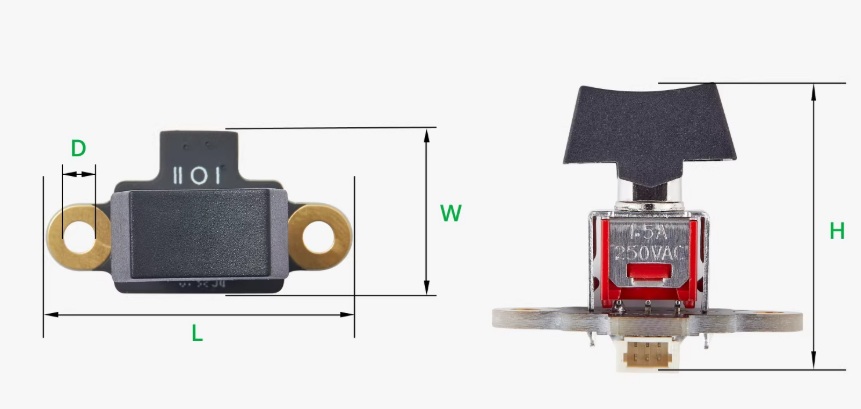 | 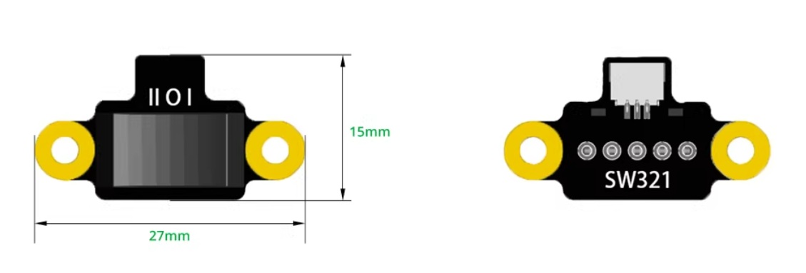 |
|---|
2.4.2 Working Principle
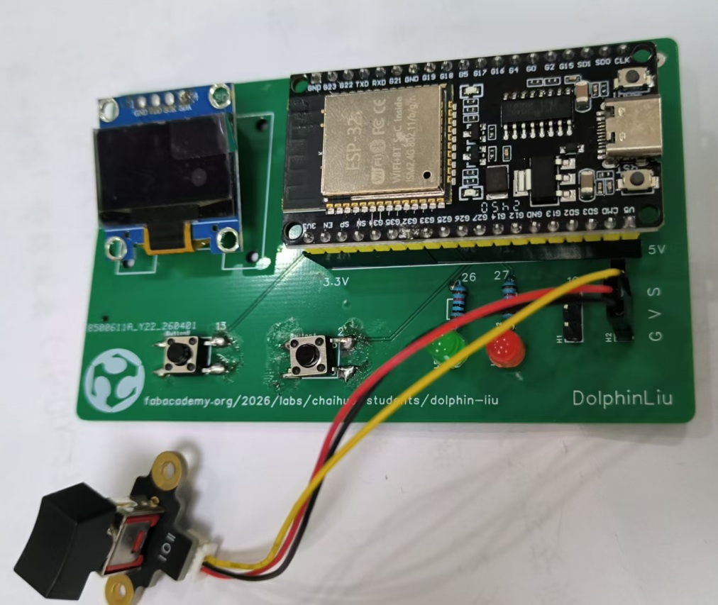
2.4.3 Connect the switch to my PCB.
I connect the 3pin switch to the 3p pin header.
| Wire Color | Pin | Function |
|---|---|---|
| Black | G | Ground (GND / -) |
| Red | V | Power (VCC / +) |
| Yellow | S (GPIO18) | Signal (SIG / Data) |
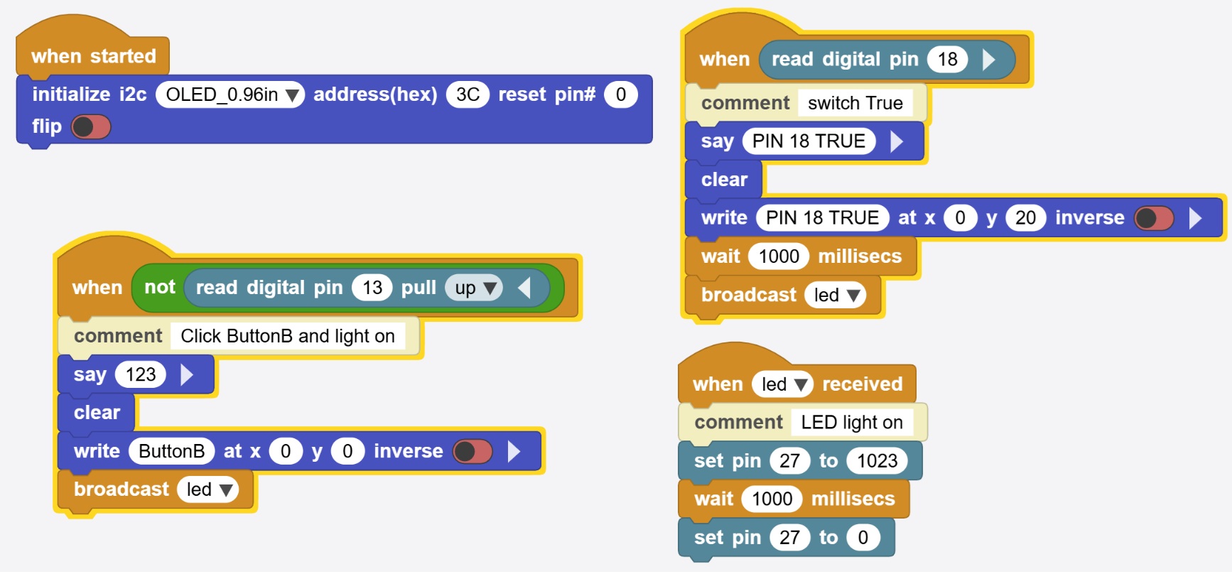
2.4.4 I write block code in MicroBlocks for quick testing.
I want to press switch ,and the OLED can show the switch status,and the Led can light up.
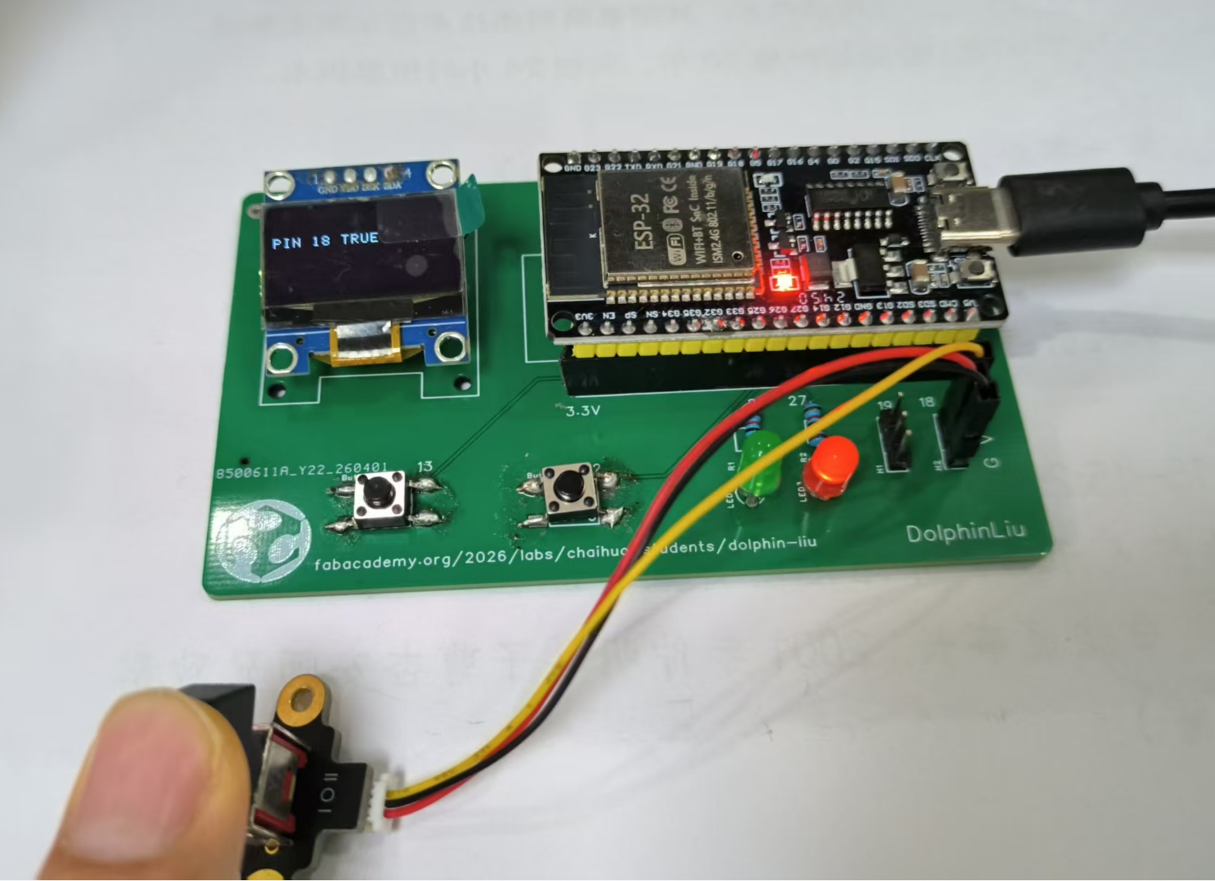
2.4.5 Testing
Here is the video of switch testing:
2.5. Lesson Learn
2.5.1 button GPIO2
Problem: Button connected to GPIO2 is not responding.
I search from google gemini and found the solution.
-
Reason: GPIO2 is a strapping pin that determines the ESP32's boot mode (it must be LOW during power-up to boot from Flash).
-
Conflict: If your button circuit pulls this pin HIGH or if the board's built-in LED (often on GPIO2) interferes with the logic, the device may fail to start or respond correctly.
-
Solution: Move the button to a non-strapping pin like GPIO12, 13, 14, or 27.
2.5.2 3pin header GPIO18,GPIO19
Problem: Rotary potentiometer connected to GPIO18/GPIO19 via 3-pin header is not working.
-
Problem: Lack of ADC Functionality
-
Reason: A potentiometer requires an ADC (Analog-to-Digital Converter) pin to read varying voltage.
-
Conflict: GPIO18 and GPIO19 do not support ADC. They are digital-only pins typically used for SPI communication (SCK and MISO).
-
Solution: Move the signal wire to an ADC1 pin (e.g., GPIO32, 33, 34, or 35). Avoid ADC2 pins if you are using Wi-Fi, as they share the same internal controller.
2.5.3 Design Considerations
I would like to design my PCB V2 with the following considerations in mind:
| Component | Current Pin | Issue | Recommended Pins |
|---|---|---|---|
| Button | GPIO2 | Strapping pin conflict | GPIO13, 14, 27 |
| Potentiometer | GPIO18 / 19 | No ADC support | GPIO32, 34, 35 |