Appearance
Week 8 - Electronics production
Group Assignment
- Characterize the design rules for your in-house PCB production process: document feeds, speeds, plunge rate, depth of cut (traces and outline) and tooling.
- Document the workflow for sending a PCB to a boardhouse
- Document your work to the group work page and reflect on your individual page what you learned
Group working
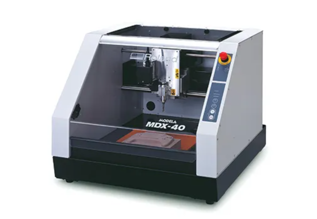
Milling Machines
In 2025, We have used the Roland MDX-40. The Roland MDX-40 3D Milling Machine is a versatile and precise desktop milling machine designed for a variety of applications, including prototyping, jewelry making, and educational purposes. It features a high-speed spindle, a robust Z-axis, and compatibility with various software, making it an excellent tool for detailed and intricate work. The detail usage workflow is documented on Xu's Electronics Production Week.
Safety first
When using the Roland Milling Machine, it's important to follow these safety precautions to ensure safe operation:
- Wear Safety Glasses: Always wear safety glasses to protect your eyes from flying debris.
- Use Dust Mask: If the operation is dusty, wear a dust mask to avoid inhaling particles.
- Secure Workpiece: Use clamps or a vise to hold the workpiece securely in place.
- Avoid Overreaching: Keep proper footing and balance at all times to avoid accidents.
- Maintain Tools: Keep tools sharp and in good condition to ensure efficient and safe operation.
- Proper Grounding: Ensure the machine is properly grounded to reduce the risk of electric shock.
- Follow Manufacturer's Instructions: Always read and follow the manufacturer's instructions and safety guidelines.
Machine Usage MDX-40
- Maximum machining range: 305 mm [X] × 305 mm [Y] × 105 mm [Z]
- Keep the table surface clean and free from debris before each job.
- Always secure the material firmly using clamps or fixtures before starting.
- Spindle speed range: 4500 to 15000 RPM
- Choose cutting speeds, depths, and feed rates appropriate to the material to maintain tool life and surface finish.
- After use, perform a tool and debris check, then power down safely.
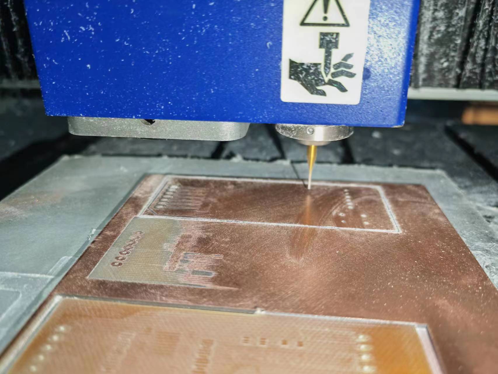
Clamping the Workpiece
- Clean the clamping platform of any impurities.
- Secure the workpiece using double-sided tape.
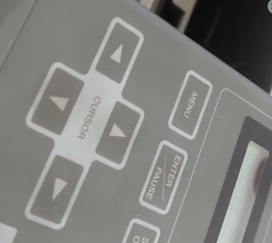
Setting the Origin
- Turn on the machine, press ENTER to return to the initial origin.
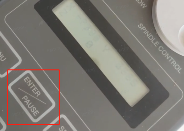
- Use the direction keys to move above the workpiece. Set the machining origin by moving the x, y, z axes to the desired origin, press ENTER twice to complete the origin setting.
Software for Roland
The software used for our Roland is MODELA Player 4.
Using the Machining Software
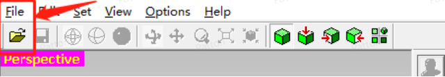
- Open the 3D data of the part to be machined.
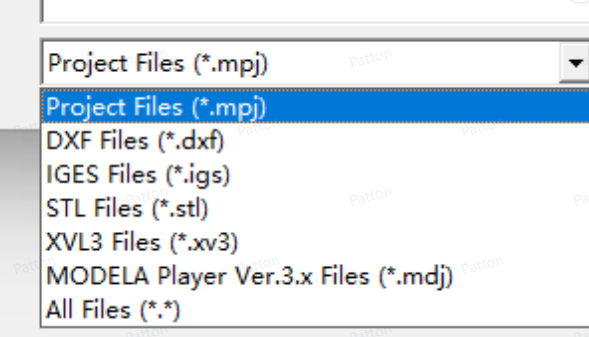
- Supported 3D data formats.
- Adjust the orientation for machining.
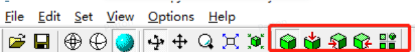
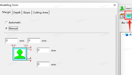
- Set the margin and machining area for the workpiece.
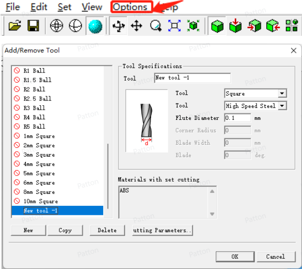
- Add the machining tool and set the diameter of the tool to be used.
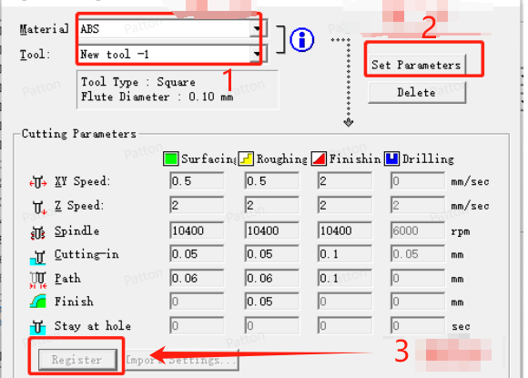
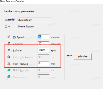
- Configure the parameters for the machining tool.
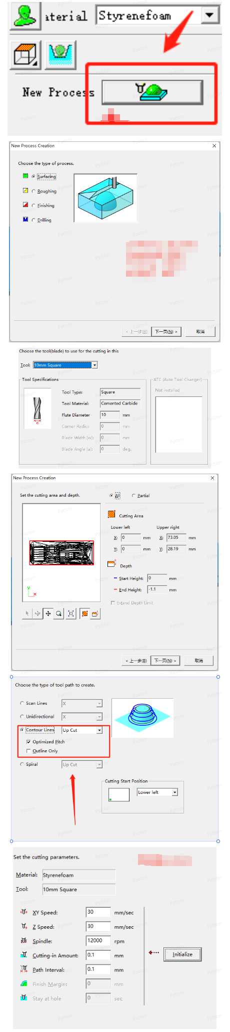
- Set the machining process.
Problems & improvements found when testing the machine
Problems
- When machining circuit boards, tools with a diameter less than 0.5 mm are prone to breaking.
- Parts cannot be fully cut off after machining.
- The surface of machined parts is rough.
- Incorrect origin setting leads to parts being machined with one side smaller.
Optimization Solutions
- When machining circuit boards, reduce the spindle speed and decrease the cutting amount.
- If the surface of machined parts is rough, increase the spindle speed and decrease the cutting amount for finishing.
Submit a PCB design to a board house
For submit a PCB design to a board house, we focusing on developing a custom expansion board based on the Seeed Studio XIAO ESP32-C3 microcontroller and send it to [LCEDA]. The board is specifically designed to integrate with A4988 stepper motor drivers, providing precise motor control capabilities. This comprehensive PCB design process encompasses everything from component selection and schematic creation to PCB layout optimization and manufacturing file generation, ensuring both functionality and manufacturability of the final product.
PCB Design Process
The LCEDA PCB design can be directly used online via link here.
Project Initialization
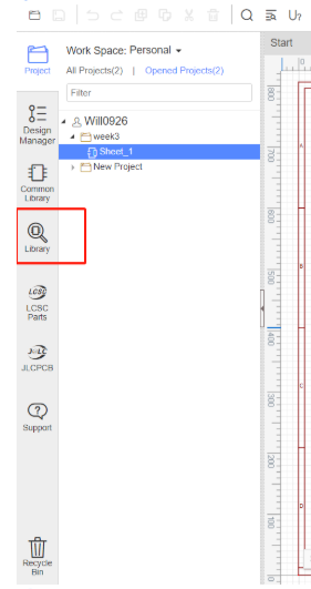
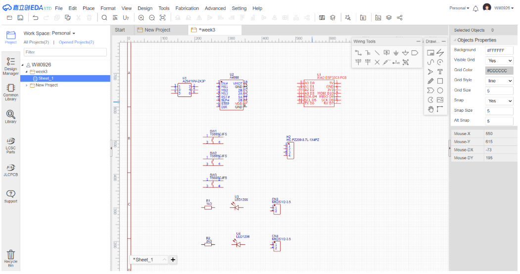
Create a new electronic design project in EasyEDA online:
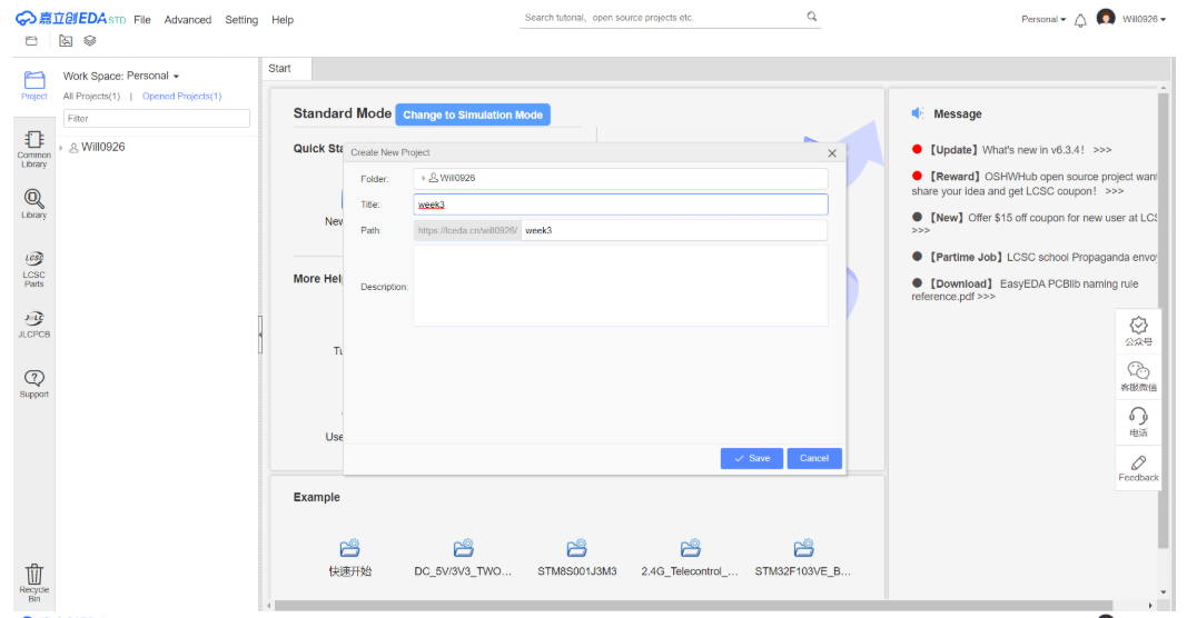
- Create a new project and select "project"
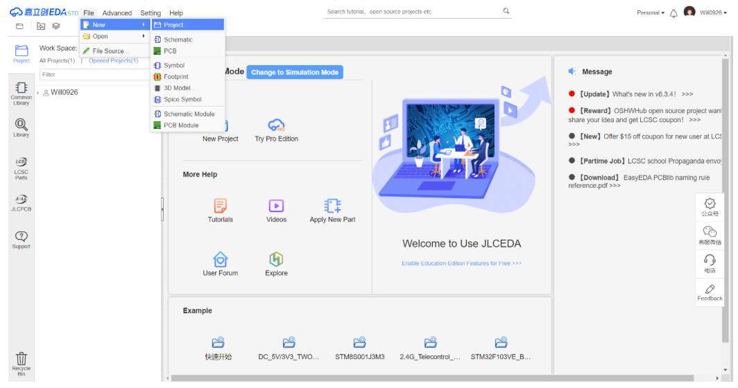
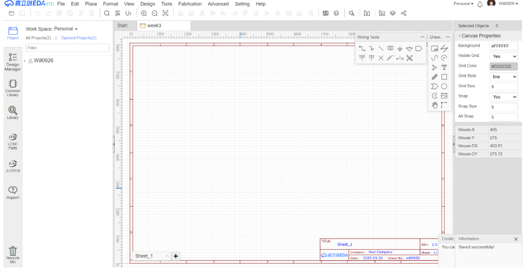
- Select "Save", then a new project is created.
- The new work space is like below.
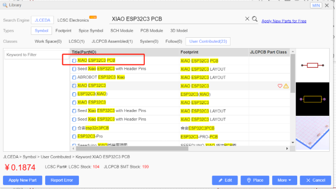
Component Library Preparation
In LCEDA, We need to use component models for the Seeed Studio Xiao ESP32-C3 and A4988 stepper motor driver. Click on "Library", then enter "XIAO ESP32C3 PCB" in the search bar, and you will find "XIAO ESP32C3 PCB", and then double click it.
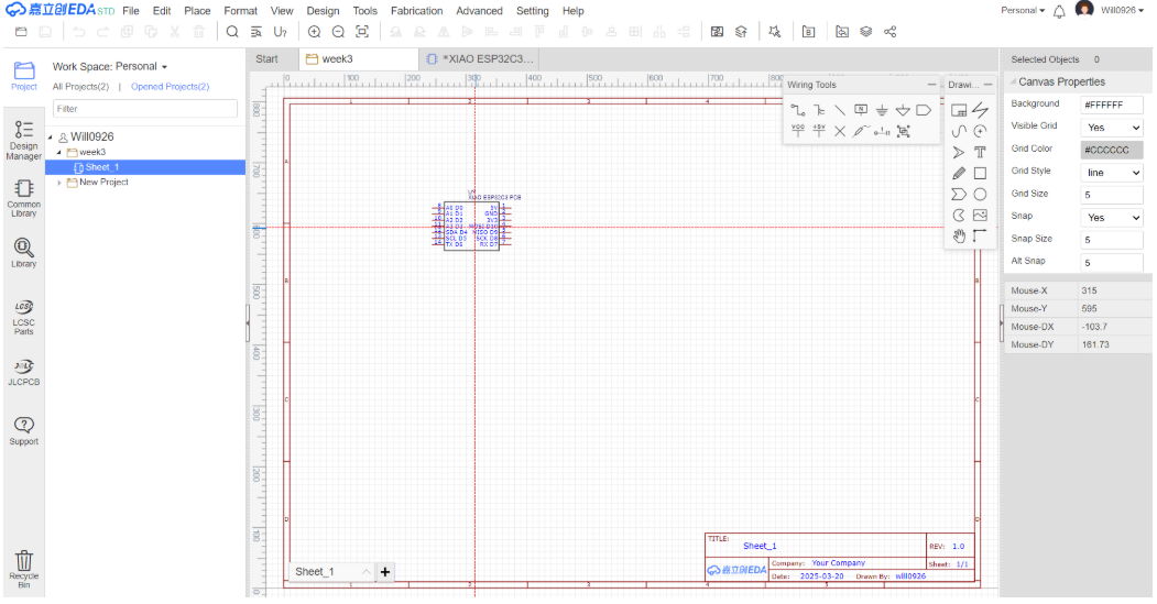
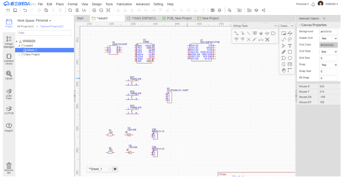
Place A4988 and other modules in the schematic using the same method
Hardware Specification Analysis
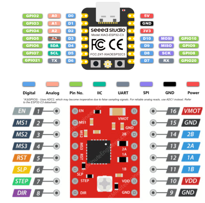
Pin Definitions
Below are the pin definitions for XIAO ESP32-C3 and A4988. Based on these definitions, I can connect four A4988 modules to the XIAO ESP32-C3 to achieve independent control of four stepper motors.
A4988 Technical Specifications
Here are the technical specifications for the A4988:
| Parameter Type | Specification |
|---|---|
| Motor Output Voltage | 8V – 35V |
| Logic Input Voltage | 3V – 5.5V |
| Continuous Current per Phase | 1A |
| Maximum Current per Phase | 2A |
| Microstepping Resolution | Full, 1/2, 1/4, 1/8, 1/16 |
Power System
A4988 requires two power connections:
- Logic Power VDD-GND: 3V-5.5V, for internal logic circuits
- Motor Power VMOT-GND: 8V-35V, for motor drive
- Note: Motor power requires decoupling capacitors to maintain current
Microstepping Control
The A4988 driver supports microstepping, which achieves finer step divisions by applying intermediate current levels to the motor coils.
- MS1/MS2/MS3: Used to select microstepping resolution, different logic level combinations can set different microstepping modes.
- Default state: Pulled down to full-step mode. For example, when driving a NEMA 17 motor (1.8° step angle, i.e., 200 steps/revolution) in quarter-step mode, the motor will execute 800 microsteps per revolution.
Motion Control
A4988 has two control input pins - STEP and DIR.
- STEP: Step control, each high-level pulse sent to this pin drives the motor according to the microstep selection pins. The faster the pulses, the faster the motor rotates.
- DIR: Direction control, high level for clockwise, low level for counterclockwise.
Power Management
- EN: Enable control, default active-low input for this pin
- SLP: Sleep mode, enters on low level
- RST: Reset control, resets on low level
Motor Output
- 1A/1B/2A/2B: Motor phase interfaces for connecting stepper motors.
Pin Assignment Plan
Below is the pin connection plan:
| Parameter Type | Specification |
|---|---|
| D0 | Motor 1 STEP |
| D1 | Motor 1 DIR |
| D2 | Motor 2 STEP |
| D3 | Motor 2 DIR |
| D4 | Motor 3 STEP |
| D5 | Motor 3 DIR |
| D6 | Motor 4 STEP |
| D7 | Motor 4 DIR |
| GND | All A4988 ENABLE |
| GND | All A4988 GND |
| 5V | All A4988 VDD |
Circuit Design Implementation
Schematic Design
- Component Placement Open your existing schematic in LCEDA. Search for the symbols of switches, resistors, and diodes in the component library. If the required components are not in the library, you need to create custom symbols for them. Drag and drop the new components onto the schematic canvas.
- Pin Connections Connect the pins of these new components to other existing components in the schematic, such as the XIAO ESP32-C3, A4988 driver, or other related parts.
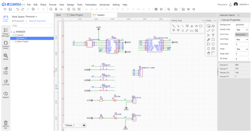
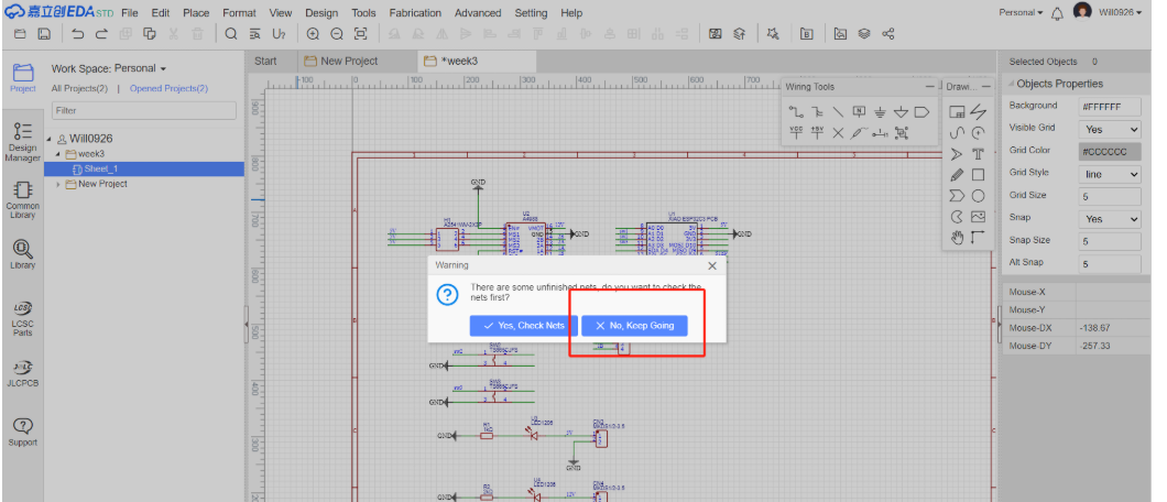
- Schematic Review Check the updated schematic for any incorrect connections, short-circuits, or missing connections. Use the error-checking tools in LCEDA to identify and fix potential issues.
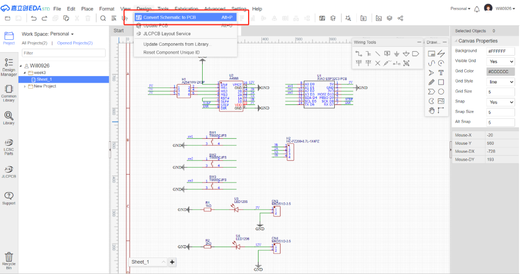
PCB Design Update
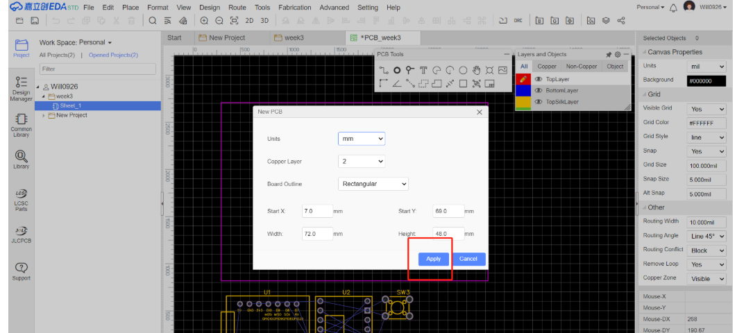
- Generate PCB from Updated Schematic: After finalizing the schematic with the new components, use LCEDA's function to transfer the updated schematic information to the PCB design area.
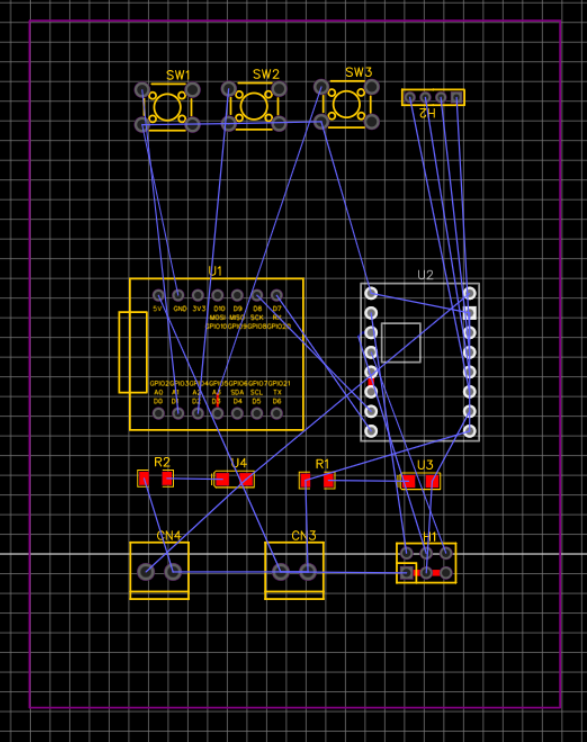
- Component Placement on PCB: Place the newly added switches and resistors on the PCB layout. Consider factors such as signal integrity, heat dissipation, and ease of assembly. Ensure that there is enough space for the new components and that they do not interfere with the existing components.
- Routing Traces: Route the electrical connections (traces) between the new component pins and other related pins on the PCB. Follow the design rules for trace width, spacing, and layer usage. For example, make sure that power traces for resistors are wide enough to handle the current. Here, we choose 5V line width 0.8mm, 12V line width 1.6mm, other line width 0.3mm
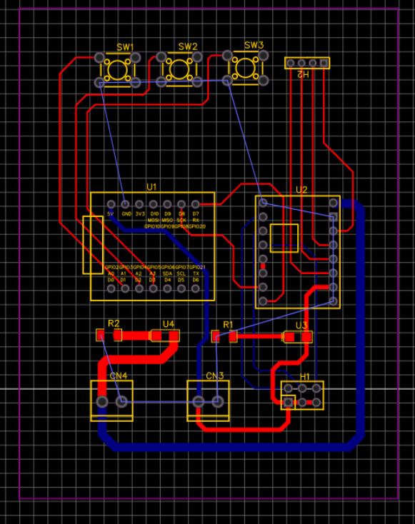
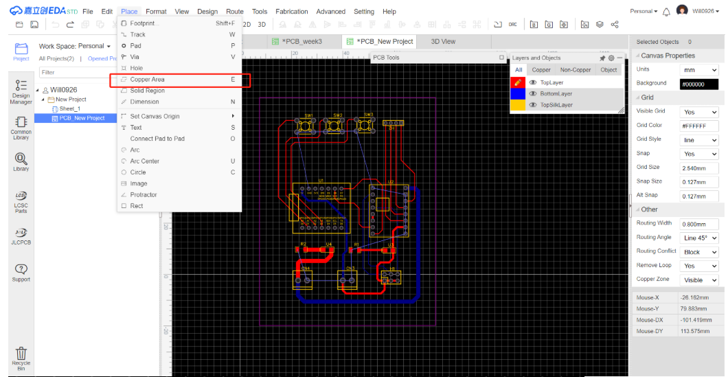
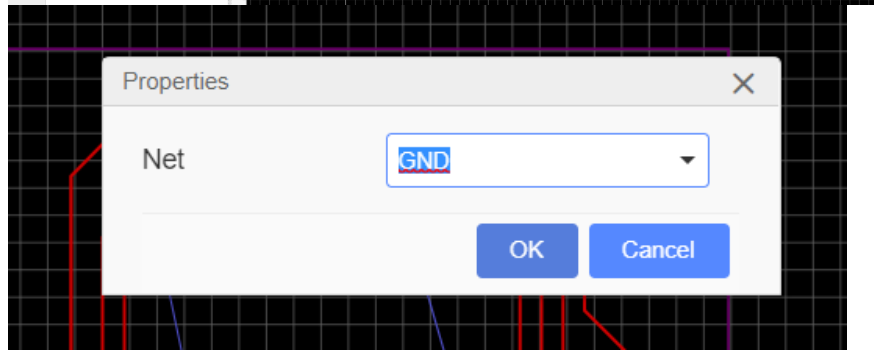
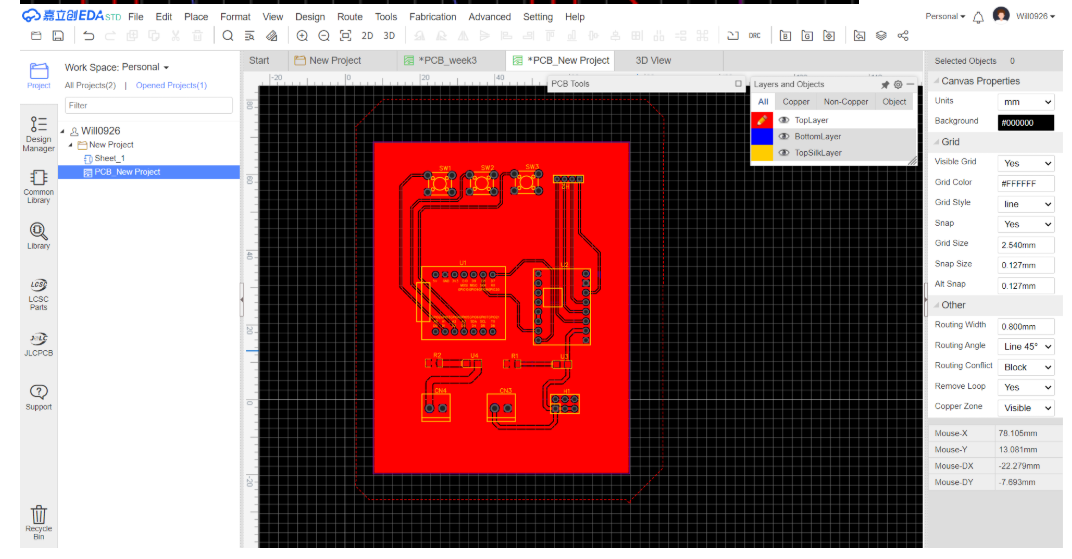
- **Ground connection:**Connect all ground interfaces with the "Copper Area" function.
- PCB Design Review: Conduct a Design Rule Check (DRC) on the updated PCB design. Check for any violations of trace-to-trace clearance, hole size, and component-to-component spacing.
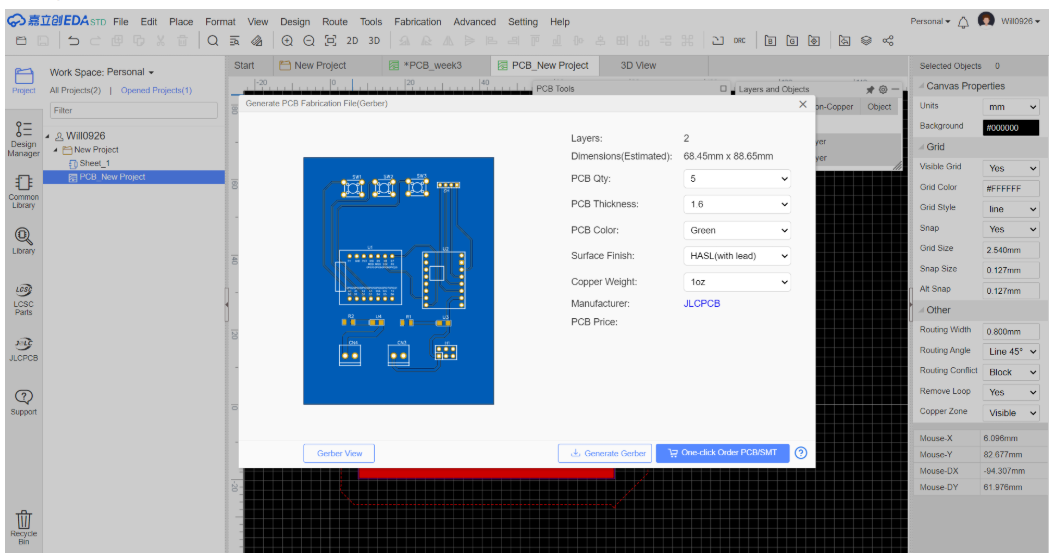
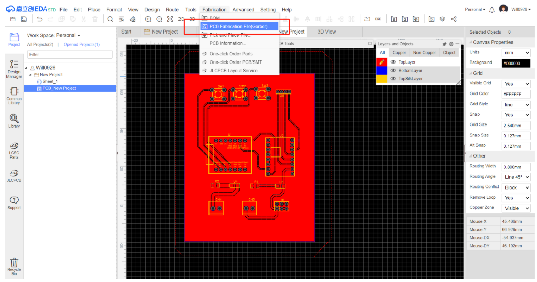
Generating Manufacturing Files
- Export Gerber Files Use LCEDA's export function to generate the Gerber files for the updated PCB design. These files will be sent to the PCB manufacturer for production.
- Update the Bill of Materials (BOM) Update the BOM to include the new components. List their part numbers, values, and quantities accurately. This will help in the procurement of components.