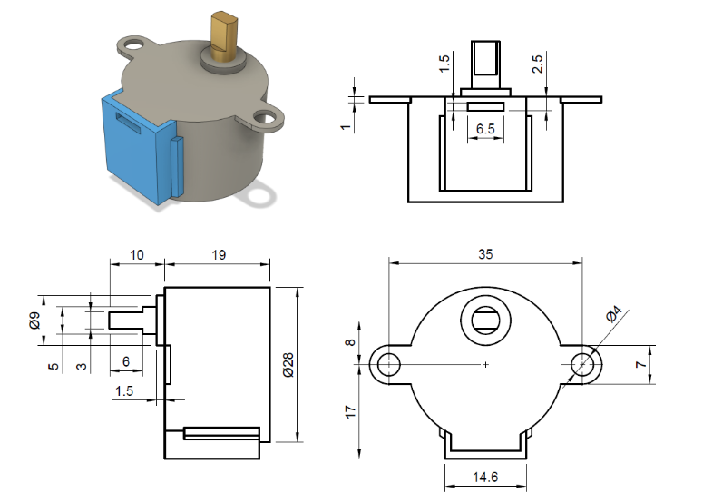
Appearance
Week 10 - Output Devices
Group Assignment
- Measure the power consumption of an output device
Group Work
Measure the power of motor
Output devices transform digitized signals into a format that can be easily comprehended by the user. They serve as the opposite of input devices by presenting the processed data in a readable format to the user. In the context of a computer or microcontroller, output devices display or convey the information generated by the system. Examples of output devices include monitors, printers, speakers, and LEDs. These devices ensure that the results of data processing are accessible and understandable to users, allowing them to make informed decisions based on the output.
Step motor
The output device we choose to use for this week is a step motor 28BYJ-48. A stepper motor is an electric motor that moves in discrete steps. Each step is a fraction of a full rotation, and the motor's position can be controlled precisely without the need for feedback systems. This makes stepper motors highly useful in applications requiring precise positioning and repeatability such as robotics joints and arms, automotive, CNC Machines, etc.
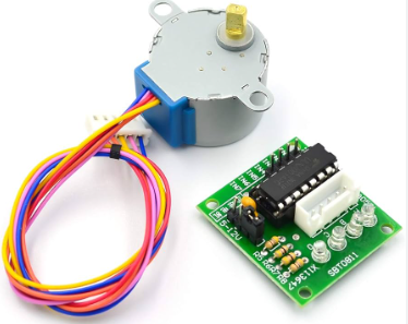
28BYJ-48 Stepper Motor
The 28BYJ-48 stepper motor is a widely used, cost-effective motor that is perfect for small projects and learning purposes. It operates on a 5V power supply and is commonly paired with a ULN2003 driver board for easy control with microcontrollers like Arduino. Here's a brief overview of its key features:
- Voltage: 5V DC
- Torque: 34.3 mN.m at around 15 RPM
- Steps per Revolution: 2048 steps (32 steps per full step, with a 64:1 gear reduction)
- Applications: Ideal for projects requiring precise positioning, such as controlling the vanes of an air conditioner unit or moving small mechanical parts.
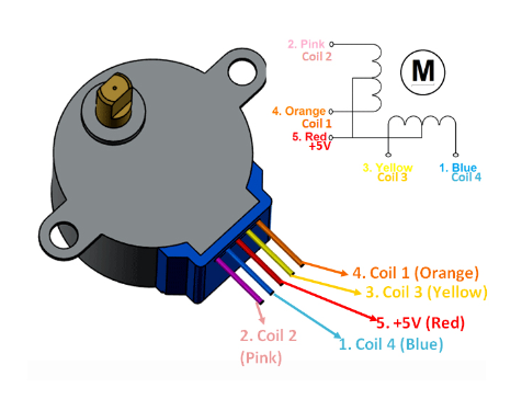
The 28BYJ-48 stepper motor has five wires: four for the coils (orange, pink, yellow, and blue) and one for the 5V power supply (red). By energizing the coils in a specific sequence, the motor rotates in precise steps, making it suitable for various DIY projects.
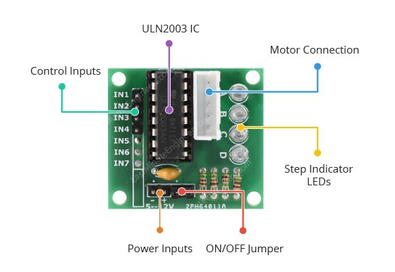
ULN2003 Stepper Motor Driver Board
Microcontrollers like Arduino typically output a maximum current of around 20-40 mA per I/O pin, which is insufficient to drive a stepper motor directly. So we need a motor driver to run the motor. The ULN2003 driver can handle higher currents and higher voltages, making it suitable for driving the coils of the stepper motor. It acts as a buffer between the microcontroller and the stepper motor, allowing the microcontroller to control the motor without being damaged by the higher currents required. Here's a brief overview of its key features:
- Voltage: 5V to 12V DC
- Current: Up to 500 mA per channel
- Control Interface: 4 input pins for stepper motor control
- Output Interface: 4 output pins connected to the stepper motor coils
- Indicators: Four LED indicators showing the activation of each coil
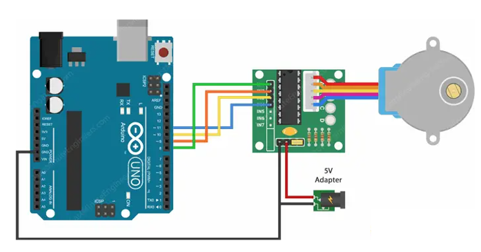
Wiring – Connecting 28BYJ-48 Stepper Motor and ULN2003 Driver Board to Arduino UNO
- The connections are straightforward. Begin by connecting an external 5V power supply to the ULN2003 driver. The stepper motor can be powered directly from the Arduino, but this is not recommended because the motor can generate electrical noise on its power supply lines, which may damage the Arduino.
- Connect the driver board’s IN1, IN2, IN3, and IN4 to Arduino digital pins 8, 9, 10, and 11, respectively. Then connect the stepper motor to the ULN2003 driver.
- Finally, make sure your circuit and Arduino share a common ground. Here is the illustration of circuit diagram.
Code for control a 28BYJ-48 Stepper Motor
The code used for running the step motor is shown as below:
#include <Stepper.h>
//define Input pins of the Motor
#define OUTPUT1   7                // Connected to the Blue coloured wire
#define OUTPUT2   6                // Connected to the Pink coloured wire
#define OUTPUT3   5                // Connected to the Yellow coloured wire
#define OUTPUT4   4                // Connected to the Orange coloured wire
// Define the number of steps per rotation
const int stepsPerRotation = 2048;  // 28BYJ-48 has 2048 steps per rotation in full step mode as given in data sheet
// Initialize the stepper motor with the sequence of control pins OUTPUT1, OUTPUT3, OUTPUT2, IN4
// OUTPUT1 and OUTPUT3 are connected to one coil and OUTPUT2 and OUTPUT4 are connected to one Coil
Stepper myStepper(stepsPerRotation, OUTPUT1, OUTPUT3, OUTPUT2, OUTPUT4);
void setup() {
  // Set the speed of the motor in RPM (adjust as needed)
  myStepper.setSpeed(15);  // 15 RPM
}
void loop() {
  // Rotate in One Direction and complete one complete rotation i.e 2048 steps
  myStepper.step(stepsPerRotation);
  delay(1000);  // Delay between rotations
  // For Rotation in opposite direction provide the variable to the parameter with negative Sign
  myStepper.step(-stepsPerRotation);
  delay(1000);  // Delay between rotations
}
Overall, the code alternates the stepper motor's rotation direction, completing one full rotation in each direction with a 1-second delay between each rotation. This creates a back-and-forth rotational motion for the motor.
Measure the power output
We have used an UNI-T UTP1306S power supply to directly measure the power output.
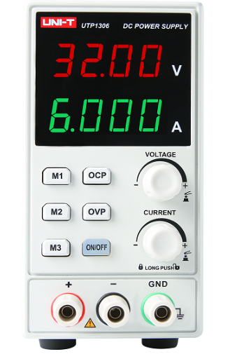
The UTP1306S power supply is an economical switching DC power supply with a single output.
- Rated output voltage 0~32V
- Rated output current 0~6A
- Max Output Power 192W
- Voltage/current display resolution: 10mV/1mA
- Four-digit voltage and current display
- Overvoltage/overcurrent/overtemperature protection
- Three groups of one-button call memory values
- Can be set Flow/overvoltage protection value
- Independent output switch
- Operation button can be locked
The power supply result have shown as below while the motor is running stable, with
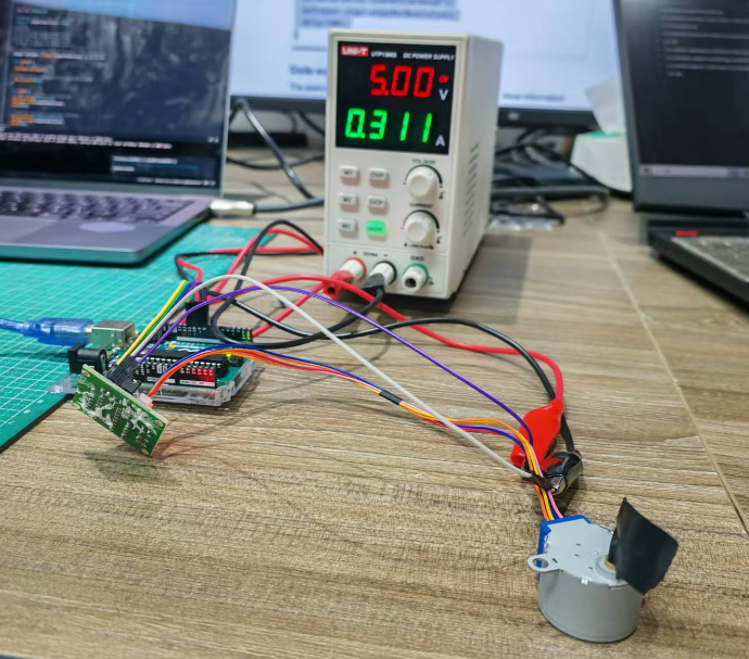
For the average 0.311 amperes with a constant voltage of 5, then we have the overall power output calculated as: P =I * V =0.311 X 5 =1.555 watt The resistance can be calculated as: R =V / I= 16.07 ohm
Measure the power of LED
The group assignment for this week is to measure the power consumption of an output device.
First, you need to know the formula for calculating power:
𝑃 = 𝑈 × 𝐼
P is power, measured in watts (W)
U is voltage, measured in volts (V)
I is current, measured in amperes (A)
Calculate the actual power consumption: I used an adjustable power supply to independently power the WS2812, while the XIAO ESP32-C3 is only responsible for signal control. Both share a common ground to ensure the signal is transmitted correctly.
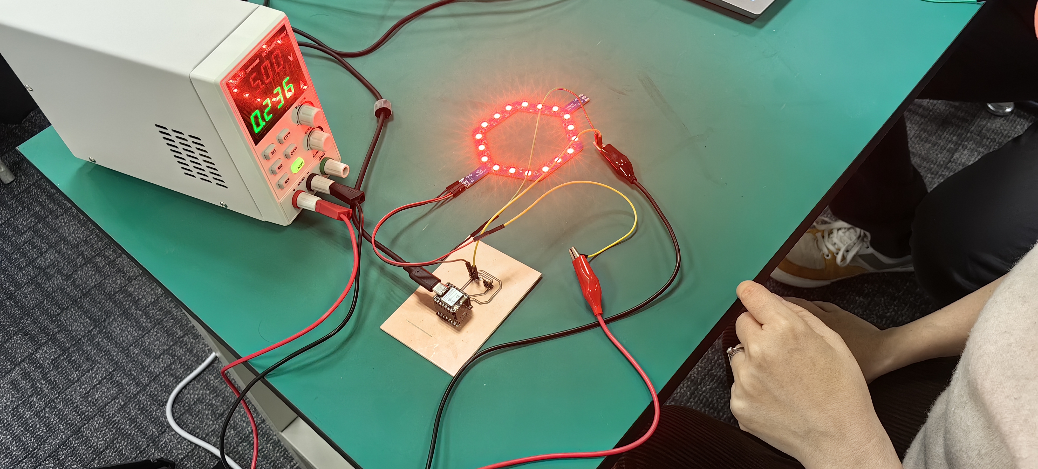
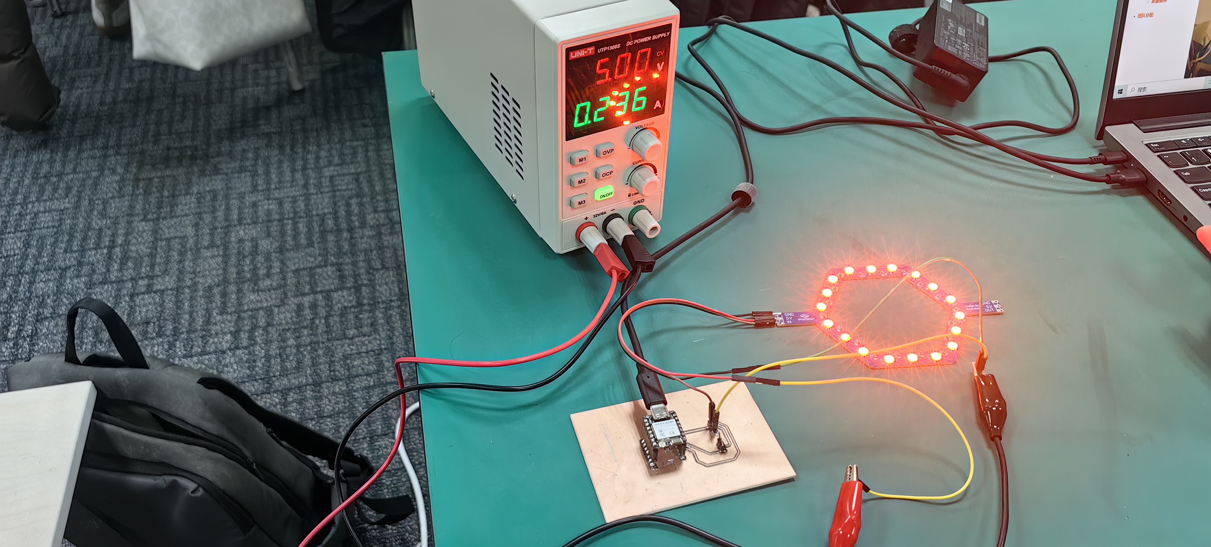
Based on the adjustable power supply information, the voltage is 5V and the current is 0.236A. Using the formula, the power consumption is calculated as:
𝑃=5𝑉×0.236𝐴=1.18𝑊att
Thus, it is concluded that the power required to illuminate 18 WS2812 LEDs is 1.18W.