Final Project
 Stellar vest © 2025 by Adriana Mexicano is licensed under CC BY-NC-SA 4.0
Description of the project
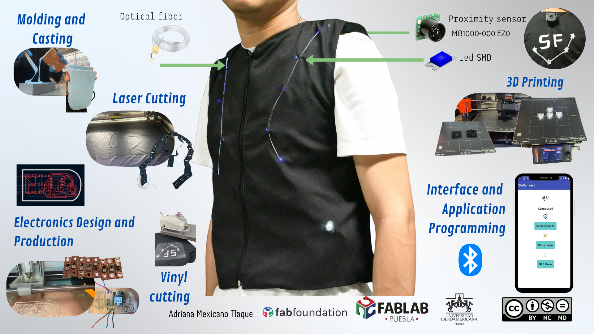
For my project, I will develop a wearable vest with sensors and outputs, focusing on security applications.
The vest includes LED lights and optical fiber; when someone approaches, the LEDs are triggered.
Initial vision of the project
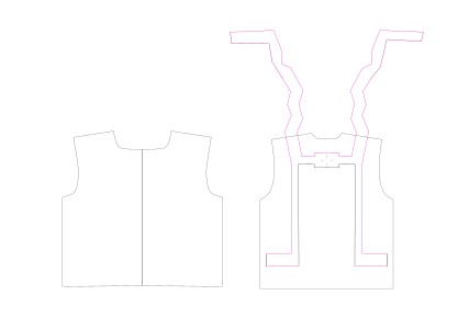
Sketch
- A proximity sensor on the back detects nearby presence
- If someone approaches too closely, the LEDs will turn on.
-compressed.jpg)
Objective
This vest helps enhance personal safety by alerting the wearer when someone is nearby.
Gantt chart
| Week | Title | Contribution to Final Project |
|---|---|---|
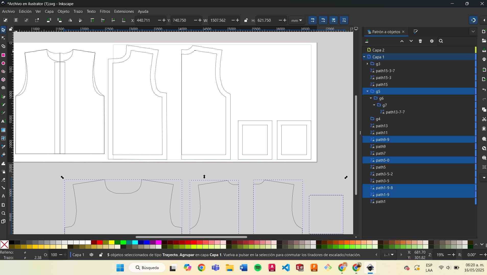
| Week 2 | Computer-Aided Design | I started the design of the vest for my final project. I explored pattern creation using Illustrator and 2D sketches to define the general shape and spaces for the electronic components. I also designed the final version of the logo that will be placed on the vest. These designs helped me visualize where the PCBs, sensors, and LEDs would be positioned on the garment. |
| Week 3 | Electronics Design | This week I began creating the first schematic for my final PCB. I tested how to use a MOSFET to control multiple high-power blue LEDs in parallel. I also defined the main components: microcontroller, connectors for LEDs . I made early designs in KiCad. |
| Week 14 | Molding and Casting | I created a custom case for the final PCB using 3D printing and silicone molding. The case was designed to protect the board from humidity, impacts, and movement inside the wearable.This case is essential to integrate electronics safely into the vest. |
| Week 15 | Interface and Application Programming | I started testing the ultrasonic sensor (LV-MaxSonar-EZ) with my XIAO RP2040 board. I wrote code to read analog values from the sensor and detect distances accurately. |
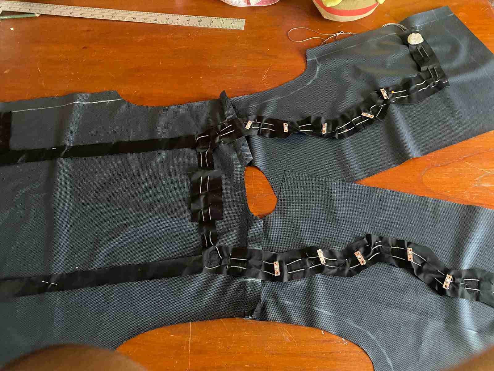
| Week 16 | System Integration | I worked on sewing the final vest and placing the conductive thread inside. I tested the continuity of the thread to ensure electrical connections worked properly. I placed the PCB case, sensor, and LED strips in their final positions. This week was key to combining electronics with textiles, making sure the wearable remains functional and comfortable. |
| Week 18 | Applications and Implications, Project Development | I analyzed the real-life use of my project. The vest is meant for artistic expression and interaction—using light and movement triggered by proximity. |
| Week 19 | Invention, Intellectual Property and Income | I considered the originality of my project and how I could share it. I'm thinking of publishing it under a Creative Commons license to allow others to replicate or modify it for educational or artistic purposes. I also explored potential opportunities for presenting it at exhibitions or wearable tech events. |
System Integration
On the outside, only the light from the LEDs will be visible, since the LEDs will be placed on the inside of the vest.
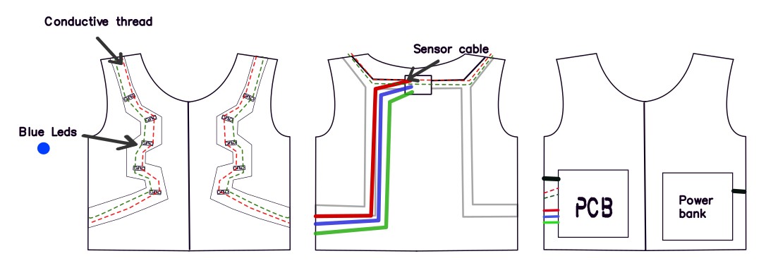
The organization of the electronic components includes the use of conductive thread to connect the LEDs and the sensor.
First part
This was the part that gave me the most problems, but I was able to solve it.
Some Attempts
First, I decided to try the sensor and programmed it to turn on the LEDs.
I had to do several tests. When it was ready, I just added it to the vest.
But...
When the time came to test it, it gave incorrect distance readings.
So, I decided to run some tests to compare the real distance with the sensor readings.
| Analog Voltage | Real Distance (cm) | Sensor Reading (cm) |
|---|---|---|
| 0.236 | 116 | 36 |
| 0.142 | 75 | 22 |
| 0.88 | 46 | 14 |
| 0.265 | 110 | 41 |
From this, I created a formula:
Distance in cm = 513.3 × Voltage - 5.2
With this, I can obtain a correct distance measurement.
Inputs and outputs
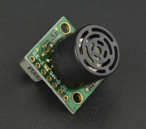
The sensor I used for this project was the MB1000 LV-MaxSonar-EZ0.
The LV-MaxSonar-EZ0 is the highest sensitivity and widest beam sensor of the LV-MaxSonar-EZ sensor series. The wide beam makes this sensor ideal for a variety of applications including people detection, autonomous navigation, and wide beam applications
With this sensor i decided to use the analogic output
- Minimum reported distance: 6 inches (15.2 cm). Objects closer than that are reported as 6".
- Near-field error zone: Objects between 6" and 20" may have up to 2" error due to acoustic phase effects.
- Power-up calibration: No objects should be near the sensor during the first read cycle (ideal: 14", minimum: 7").
- Recalibration: Required if temperature, humidity, or voltage changes. Power-cycle the sensor to recalibrate.
- Power supply: Operates from 2.5V to 5.5V, with typical current draw of 2mA.
- Read frequency: Can perform readings every 50 ms (20 Hz).
- Analog output (Pin 3 - AN): Scales with distance: Vcc/512 per inch (at 3.3V: ~6.4mV/inch).
- Available interfaces: Serial TTL (9600 baud), Analog, and PWM (147 µs/inch).
#include

#define analogPin A2     // Sensor pin
#define ledPin D0        // LED pin
#define N 5              // Number of readings for average

// Variables for blinking
bool ledState = false;
unsigned long previousMillis = 0;
const long interval = 500;  // Blinking interval in ms

String mode = "off";  // Modes: "safe", "blink", "off"

// BLE service and characteristics
BLEService ledService("12345678-1234-1234-1234-1234567890ab");

BLEIntCharacteristic safeChar("00000001-0000-1000-8000-00805f9b34fb", BLEWrite);
BLEIntCharacteristic blinkChar("00000002-0000-1000-8000-00805f9b34fb", BLEWrite);
BLEIntCharacteristic offChar("00000003-0000-1000-8000-00805f9b34fb", BLEWrite);

// --- LED-on timer control variables ---
bool ledOn = false;
unsigned long onTime = 0;
const unsigned long LED_DURATION = 10000;  // 10 seconds in milliseconds

// BLE button state tracking
int lastSafeVal = 0;
int lastBlinkVal = 0;
int lastOffVal = 0;

// --- Sensor functions ---
int readSensorAverage(int pin, int samples = 10) {
  long sum = 0;
  for (int i = 0; i < samples; i++) {
    sum += analogRead(pin);
    delay(5);
  }
  return sum / samples;
}

float adcToVoltage(int adcValue, float Vref = 3.3, int resolution = 4095) {
  return (adcValue * Vref) / resolution;
}

float voltageToCalibratedDistance(float voltage) {
  return 513.3 * voltage - 5.2;  // Calibrated formula
}

float getAverageDistance() {
  float sum = 0;
  for (int i = 0; i < N; i++) {
    int adc = readSensorAverage(analogPin);
    float voltage = adcToVoltage(adc);
    float distance = voltageToCalibratedDistance(voltage);
    sum += distance;
    delay(20);
  }
  return sum / N;
}

void setup() {
  Serial.begin(115200);
  pinMode(ledPin, OUTPUT);
  digitalWrite(ledPin, LOW);

  if (!BLE.begin()) {
    Serial.println("Error starting BLE");
    while (1);
  }

  BLE.setLocalName("BLE_LEDS");
  BLE.setAdvertisedService(ledService);

  ledService.addCharacteristic(safeChar);
  ledService.addCharacteristic(blinkChar);
  ledService.addCharacteristic(offChar);

  BLE.addService(ledService);
  BLE.advertise();

  Serial.println("Waiting for BLE connection...");
}

void loop() {
  BLEDevice central = BLE.central();

  if (central) {
    Serial.print("Connected to: ");
    Serial.println(central.address());

    while (central.connected()) {
      handleBLE();
      handleMode();
    }

    Serial.println("Disconnected");
    mode = "off";
    digitalWrite(ledPin, LOW);
    ledOn = false;
    ledState = false;
  }
}

void handleBLE() {
  int safeVal = safeChar.value();
  int blinkVal = blinkChar.value();
  int offVal = offChar.value();

  // Detect changes to avoid unnecessary repetition
  if (offVal == 3 && offVal != lastOffVal) {
    mode = "off";
    Serial.println("Off Mode");
    digitalWrite(ledPin, LOW);
    ledOn = false;
    ledState = false;
  }
  else if (safeVal == 1 && safeVal != lastSafeVal) {
    mode = "safe";
    Serial.println("Safe mode (sensor)");
    digitalWrite(ledPin, LOW);
    ledOn = false;
    ledState = false;
  }
  else if (blinkVal == 2 && blinkVal != lastBlinkVal) {
    mode = "blink";
    Serial.println("Blink mode");
    digitalWrite(ledPin, LOW);
    ledOn = false;
    ledState = false;
    previousMillis = millis();
  }

  // Update last values
  lastSafeVal = safeVal;
  lastBlinkVal = blinkVal;
  lastOffVal = offVal;
}

void handleMode() {
  if (mode == "off") {
    digitalWrite(ledPin, LOW);
    return;
  }

  else if (mode == "safe") {
    float distanceCm = getAverageDistance();
    Serial.print("Calibrated distance: ");
    Serial.print(distanceCm, 1);
    Serial.println(" cm");

    unsigned long now = millis();

    if (distanceCm >= 100.0 && distanceCm <= 150.0 && !ledOn) {
      digitalWrite(ledPin, HIGH);
      ledOn = true;
      onTime = now;
      Serial.println("LED turned on for 10 seconds");
    }

    if (ledOn && (now - onTime >= LED_DURATION)) {
      digitalWrite(ledPin, LOW);
      ledOn = false;
      Serial.println("LED turned off after 10 seconds");
    }
  }

  else if (mode == "blink") {
    unsigned long now = millis();

    if (now - previousMillis >= interval) {
      previousMillis = now;
      ledState = !ledState;
      digitalWrite(ledPin, ledState ? HIGH : LOW);
    }
  }
}
1. Libraries and Initial Setup
This line includes the Bluetooth Low Energy (BLE) library:
#include <ArduinoBLE.h>These define pin numbers and settings for the LED and sensor:
#define analogPin A2
#define ledPin D0
#define N 5
2. LED Blinking Variables
Used to manage blinking behavior:
bool ledState = false;
unsigned long previousMillis = 0;
const long interval = 500;
The variable modo stores the current mode (off, blink, or sensor).
3. BLE Service and Characteristics
The BLE service and three "virtual buttons" (characteristics) for mobile app control:
BLEService ledService(...);
BLEIntCharacteristic safeChar(...);
BLEIntCharacteristic blinkChar(...);
BLEIntCharacteristic offChar(...);
4. Sensor Activation Logic (10 Seconds LED On)
These variables keep the LED on for 10 seconds if motion is detected:
bool ledOn = false;
unsigned long ledOnTime = 0;
const unsigned long LED_DURATION = 10000;
5. Sensor Reading Functions
These functions read the sensor, convert the signal to voltage, and then to distance:
leerSensorPromedio()- Averages multiple readingslecturaAVoltaje()- Converts ADC reading to voltagevoltajeADistanciaCalibrada()- Converts voltage to calibrated distancepromedioSensor()- Combines all the above for final result
6. setup() - Initial Configuration
Initializes serial monitor, LED pin, and starts BLE advertising:
- Sets local BLE name to "BLE_LEDS"
- Adds the service and characteristics
- Starts advertising the device to be discoverable by mobile
7. loop() - Main Program Loop
Waits for a BLE device to connect. Once connected, it listens for commands and reacts accordingly.
8. manejarBLE() - BLE Button Handling
This function checks if any BLE button was pressed (on the app), and updates the current mode.
safeVal == 1→ sensor modeblinkVal == 2→ blinking modeoffVal == 3→ turns everything off
9. manejarModo() - Executes Current Mode
This function performs actions based on the current mode:
- Off: LED is turned off.
- Safe mode: LED turns on for 10 seconds if an object is detected at 100–150 cm.
- Blink mode: LED blinks every 0.5 seconds.
Summary
- Uses BLE to control an LED from your phone
- 3 Modes: Off, Blink, and Distance Sensor
- Sensor is calibrated to detect a specific distance range(100cm-150cm)
- Great for safety/wearable projects!
Second Part
Molding and casting
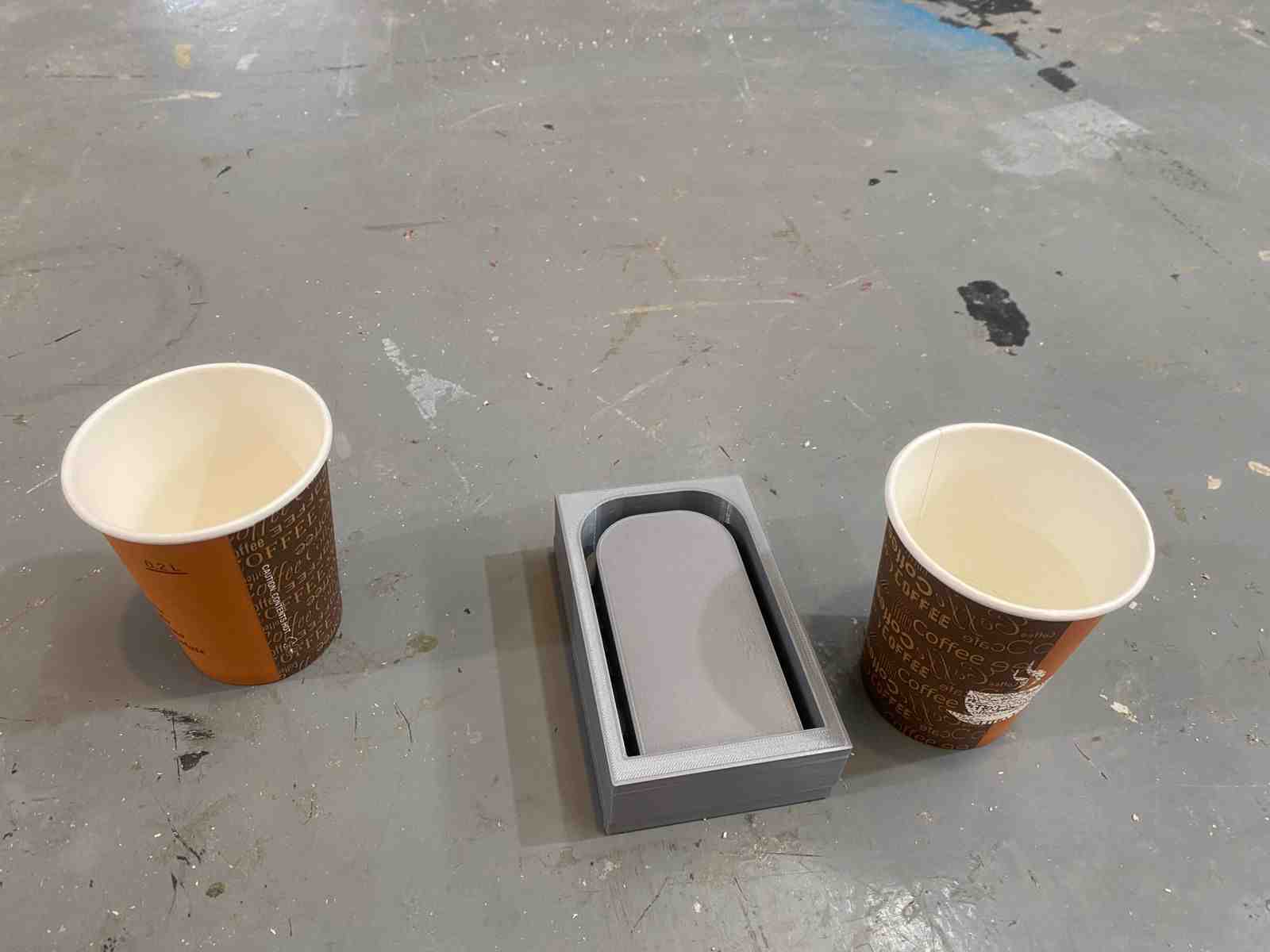
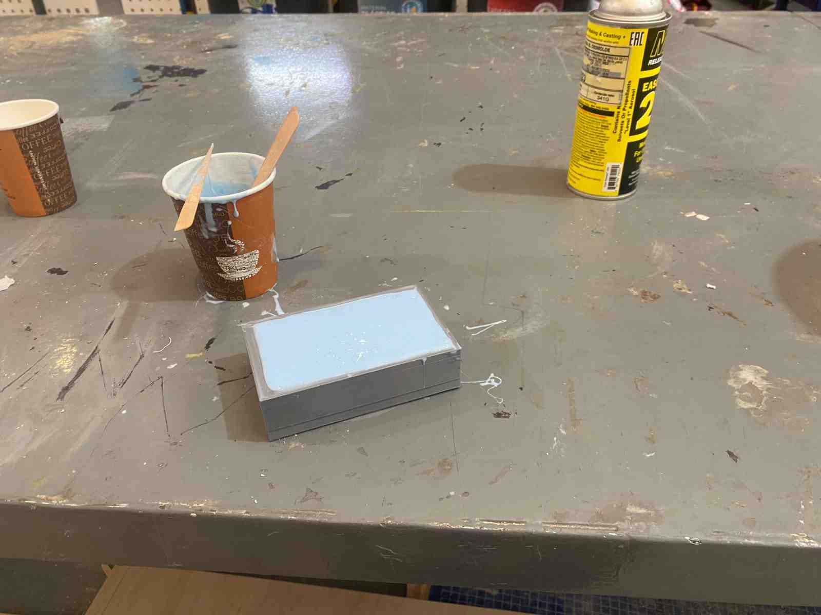
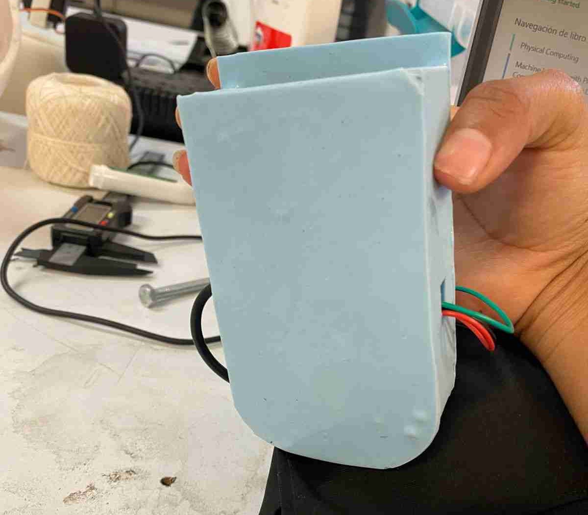
To improve comfort in the vest's pocket area, I made a flexible case for the main PCB using Silicona 930, a soft and durable material suitable for wearables. I designed a simple mold in CAD and 3D printed it. Then I mixed parts A and B of the silicone (100:10 ratio), poured it into the mold, and let it cure at room temperature. The result is a soft, flexible case that protects the electronics and adapts to body movement, making the vest more comfortable to wear.
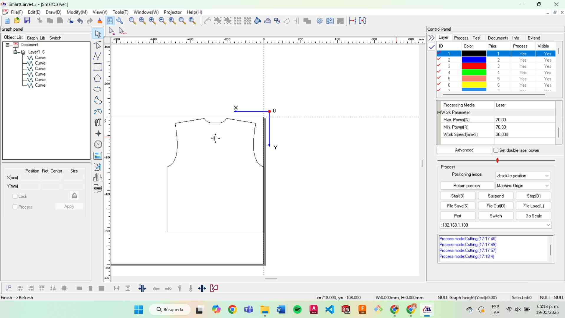
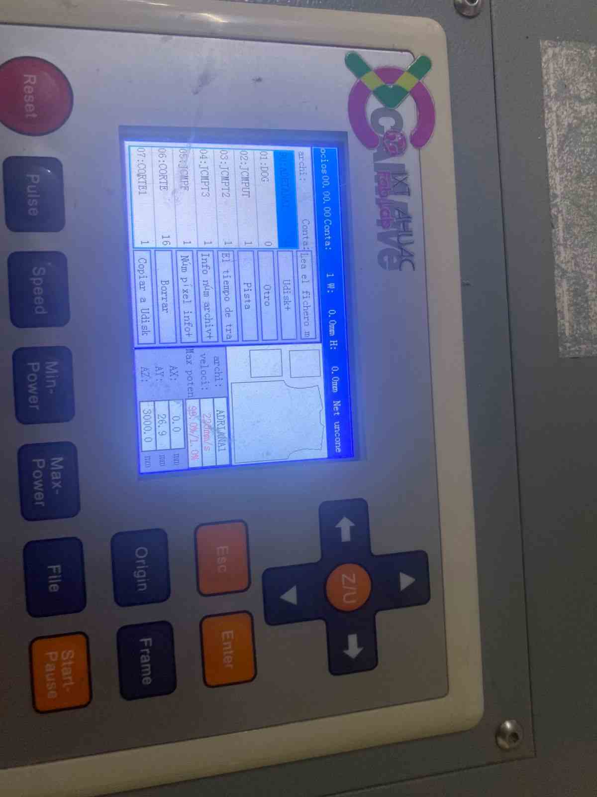
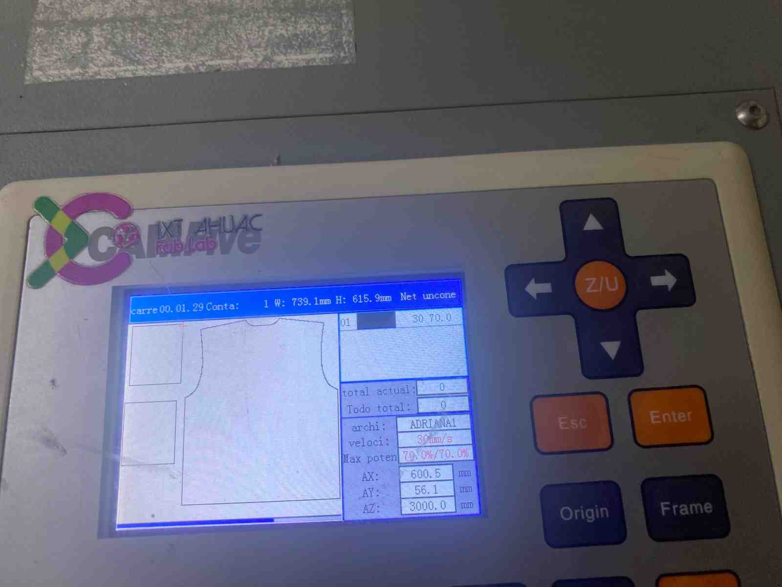
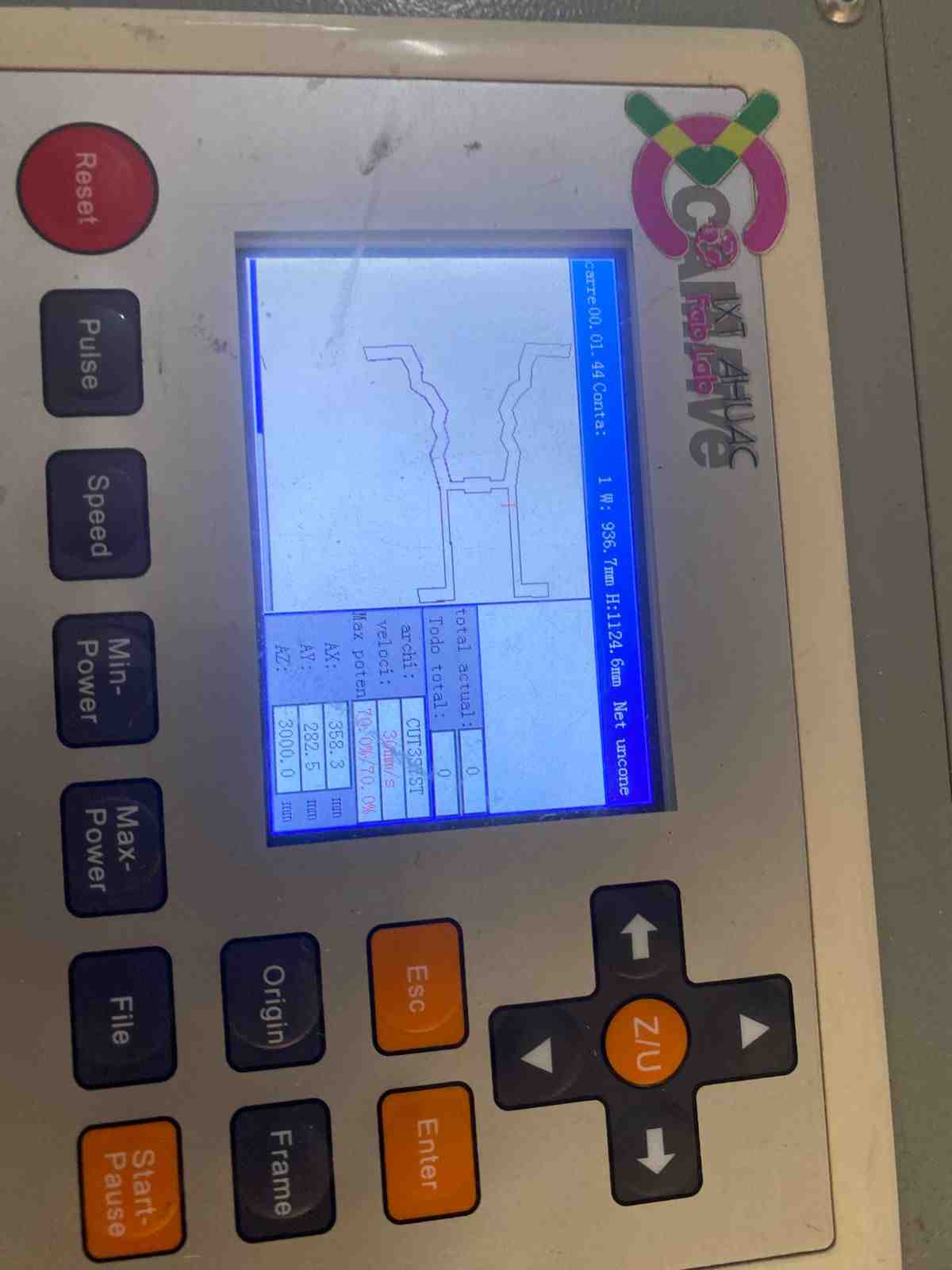
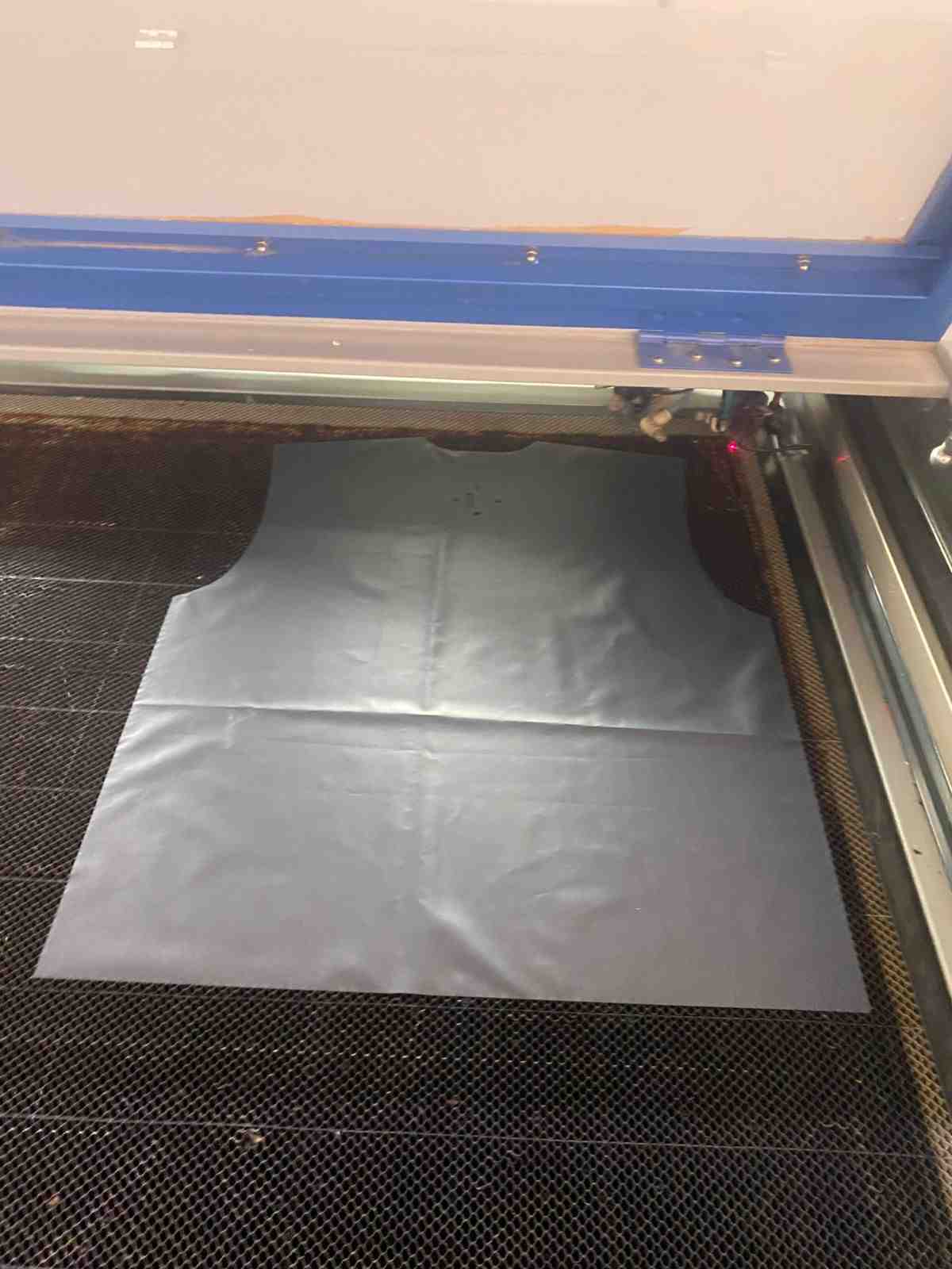
Laser Cutting
I used laser cutting to accurately fabricate the vest pieces according to a designed pattern. The vest includes pockets on the sides and holes in the back for installing the sensor.
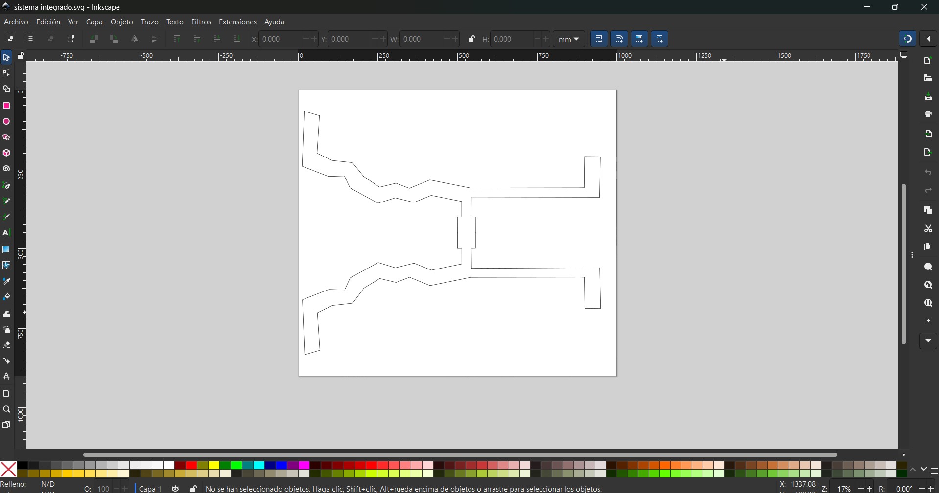
I cut the fabric pieces from 100% polyester using the following laser settings:
- Power: 70%
- Speed: 30%
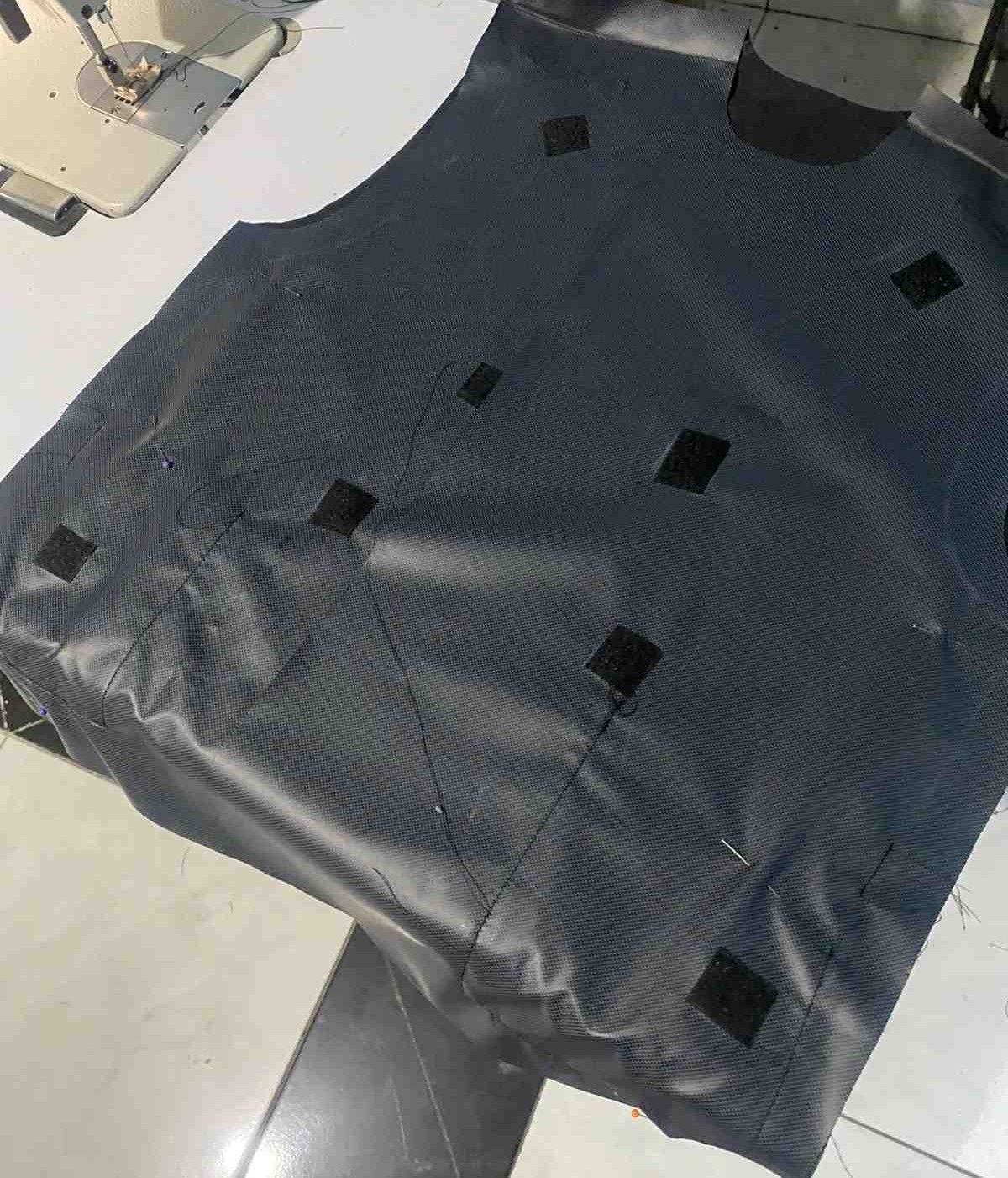
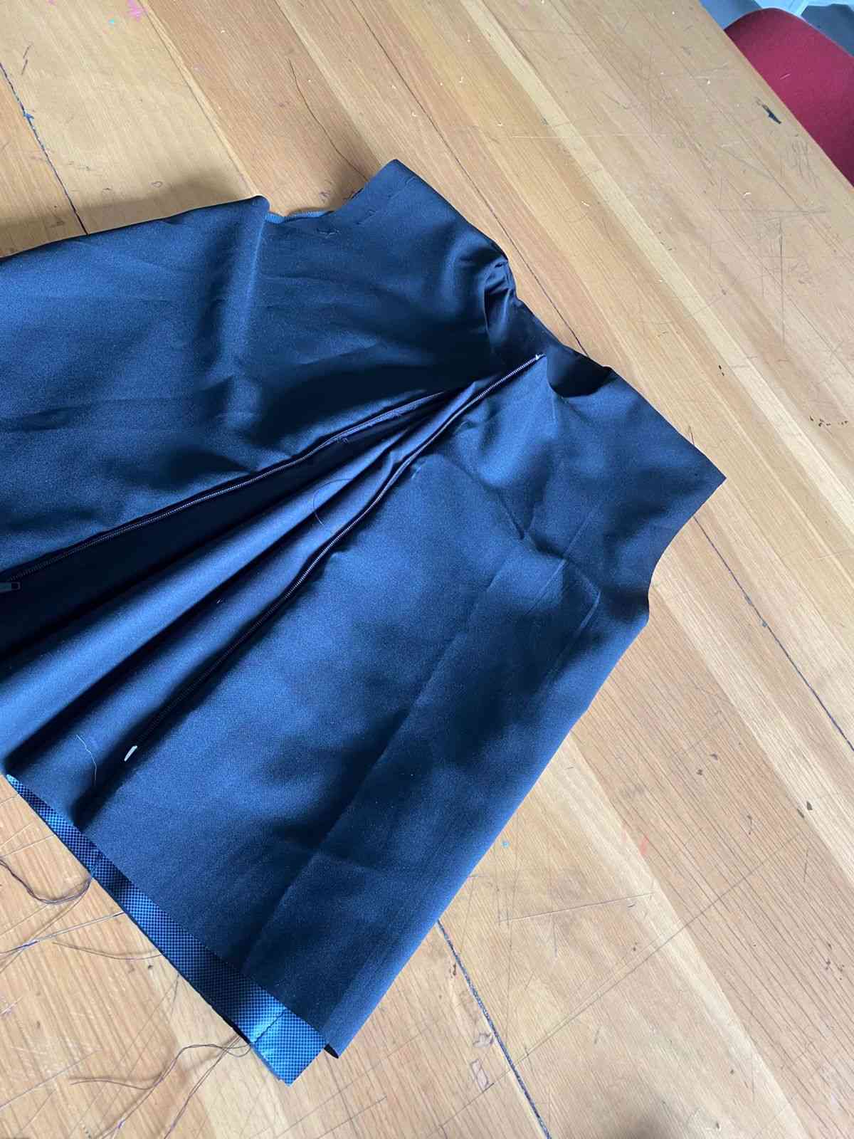
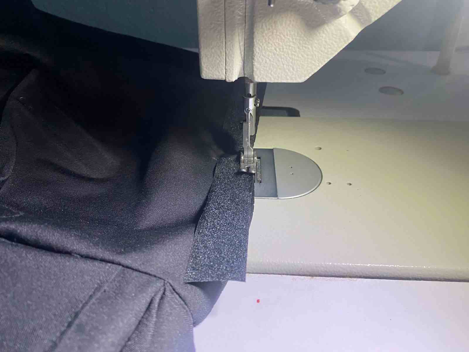
Sewing machine
For this process, I used a recta machine. In this process, I made the electronic component removable from the piece so it can be washed. I always kept the idea of a comfortable vest in mind.
3D printing
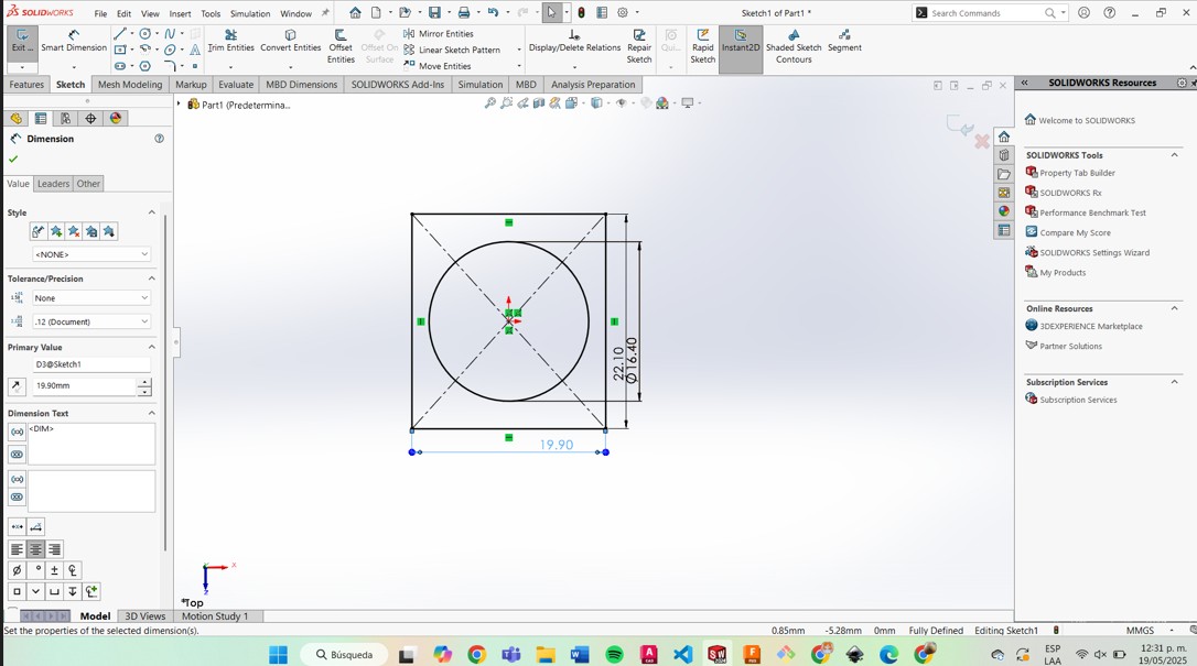
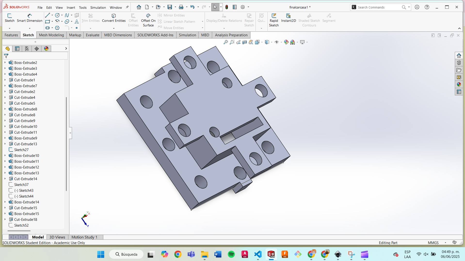
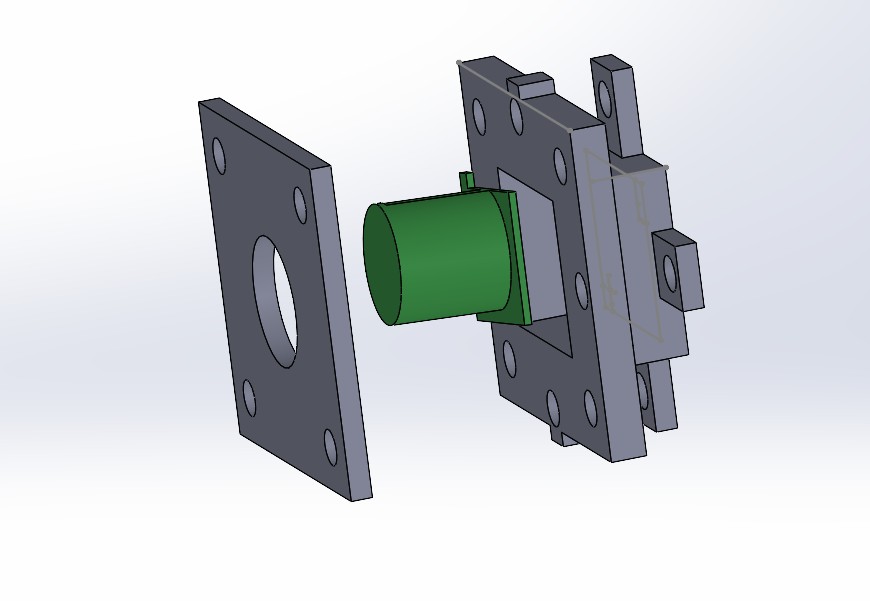
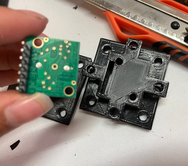
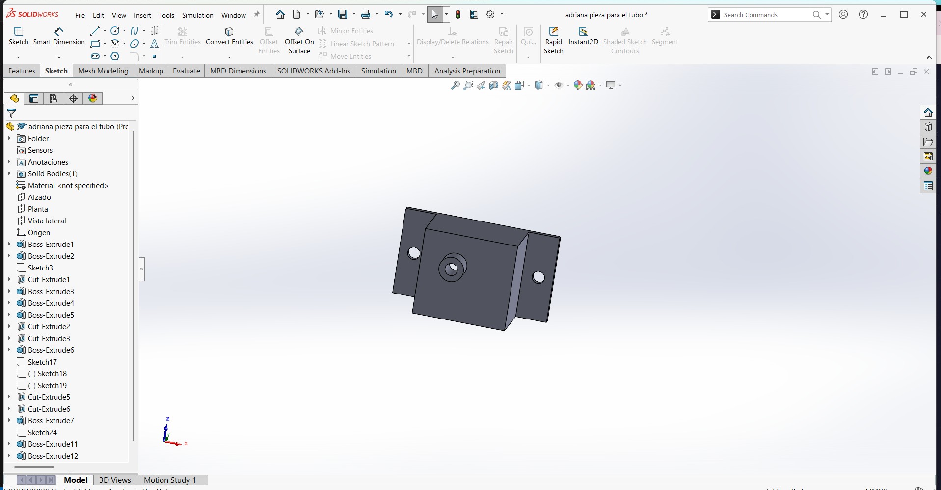
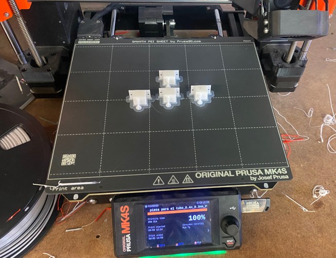
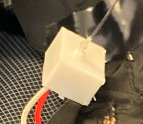
To protect the sensor, I designed a custom case using SolidWorks and printed it with a Prusa MK4. In this case, I left enough space for the sensor’s pins, included an opening to ensure proper detection, and added holes for screws to securely attach the case to the vest. I also included an extra screw to allow adjustment of the sensor’s position as needed.

Optical Fiber Modules
I designed modules to illuminate the optical fibers.
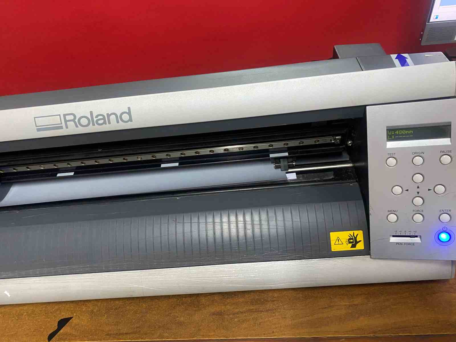
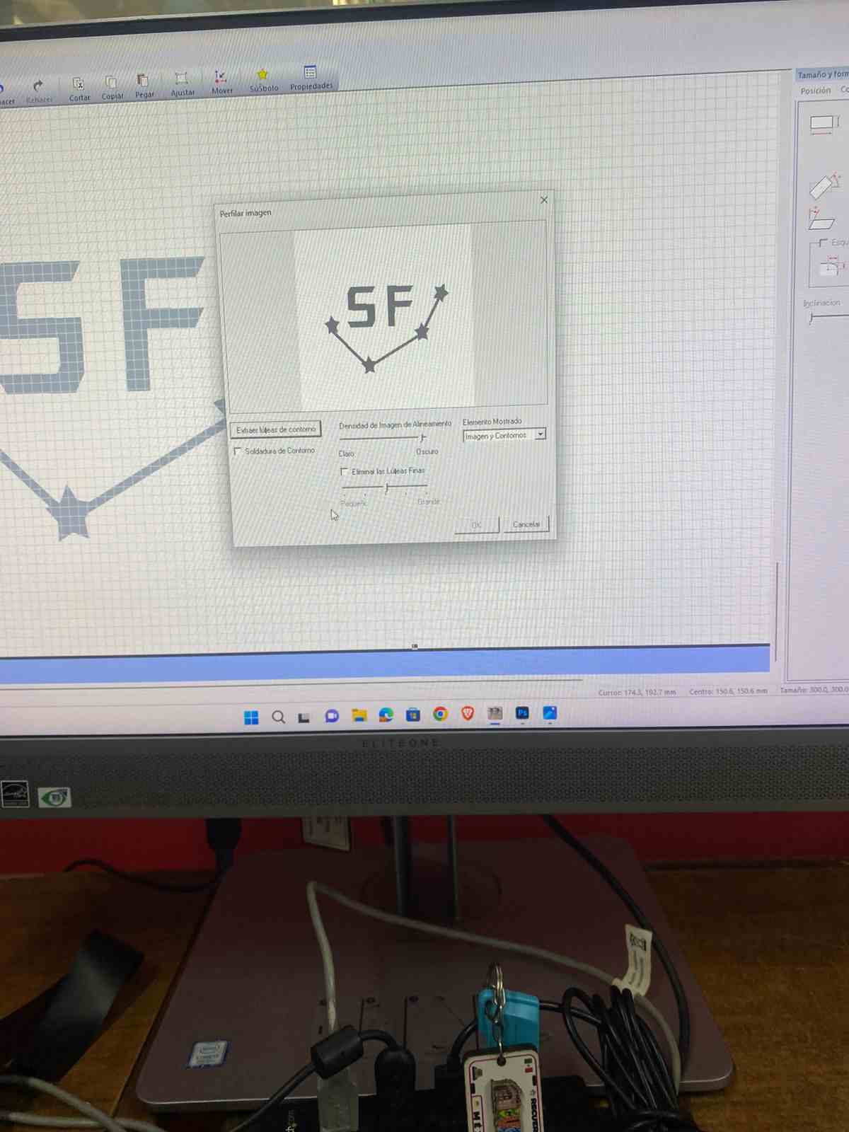
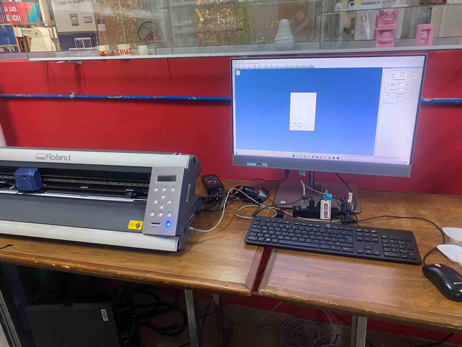
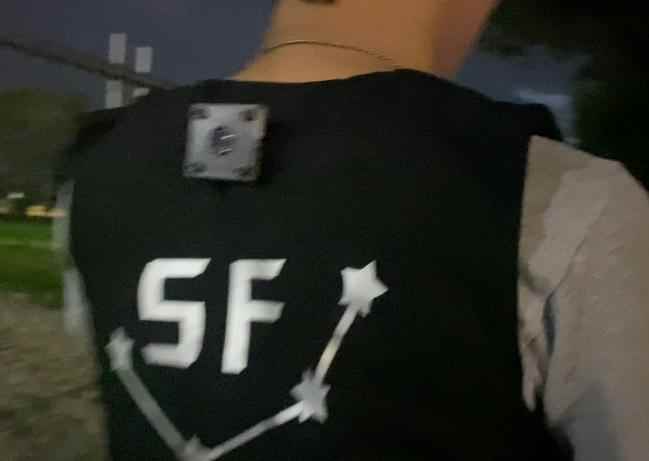
Vinyl cutting
I used textile vinyl to add my logo to the back of my vest.
I used the Roland CAMM-1 machine.
Work Parameters:
- Pressure: 150 gf
- Speed: 20 mm/s
I used the logo I created in week 2

- First, I turned on the machine.
- I placed the roll of textile vinyl in the machine by lifting and lowering the lever to secure it.
- I plugged in my USB drive, extracted my PNG image, and imported it into the program called Roland Cut Studio.
- I added the outline to my figure.
- I pressed "Origin" to have the machine size my figure.
- Then, the program cut the design.
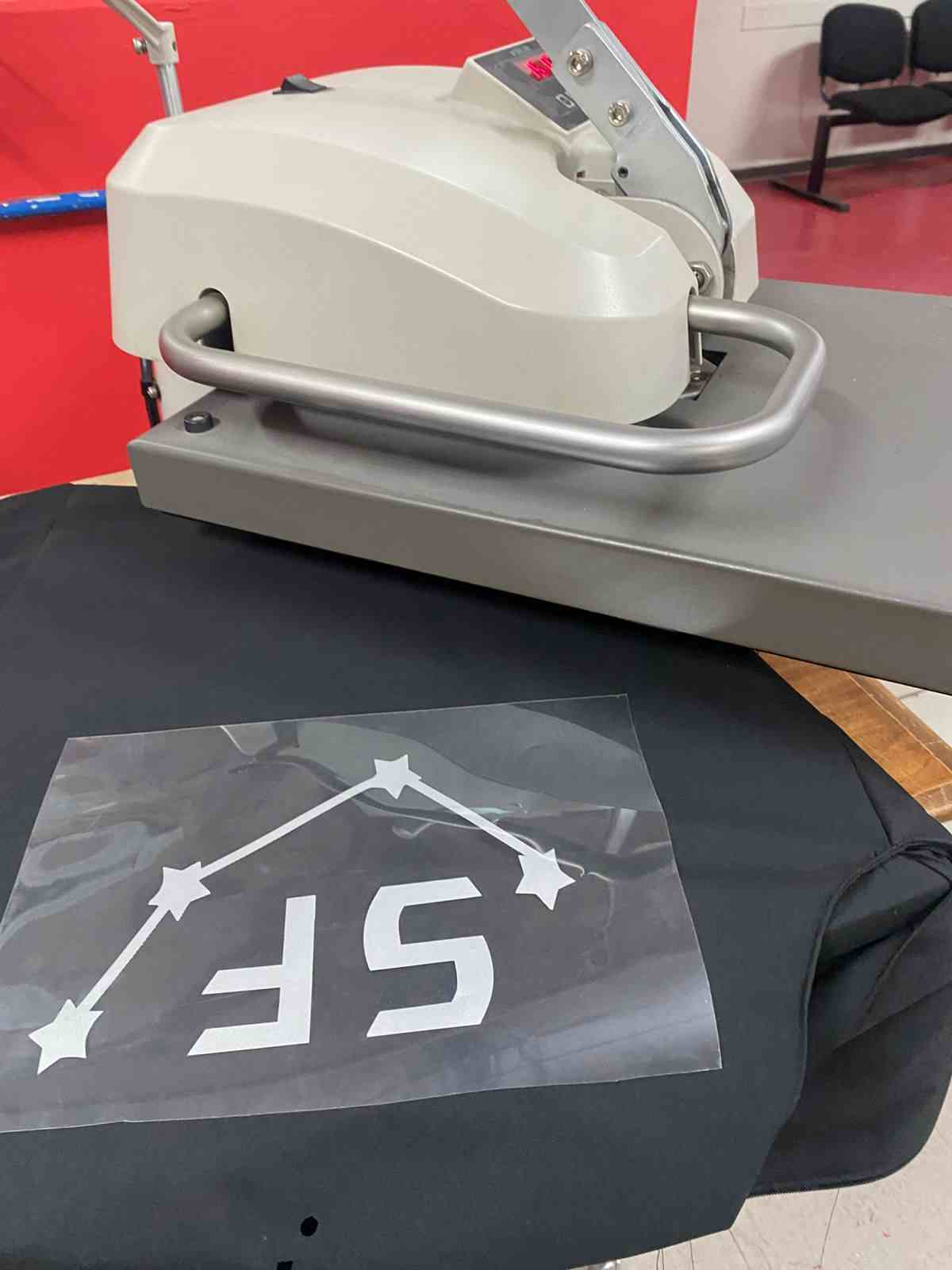
Sublimation
- I heated the machine to 150°C.
- While it was heating, I placed the design on the back part of the vest.
- When it reached the desired temperature, I pressed the machine down onto the design.
- I waited 15 seconds and then moved the press to the side.
- Finally, I removed the transparent layer and took out the vest.
third Part
Electronics desing and production
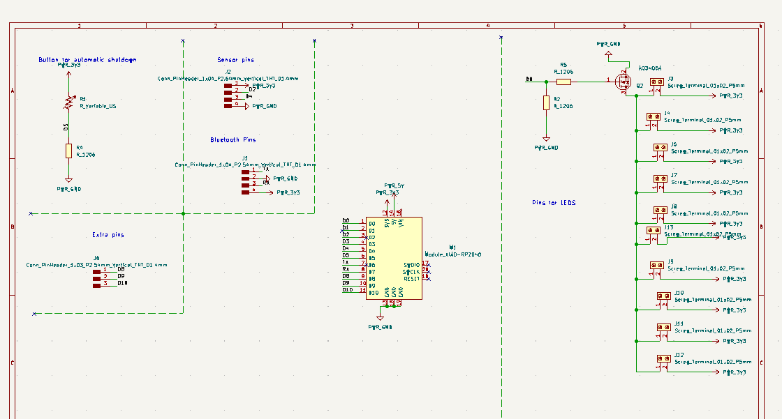
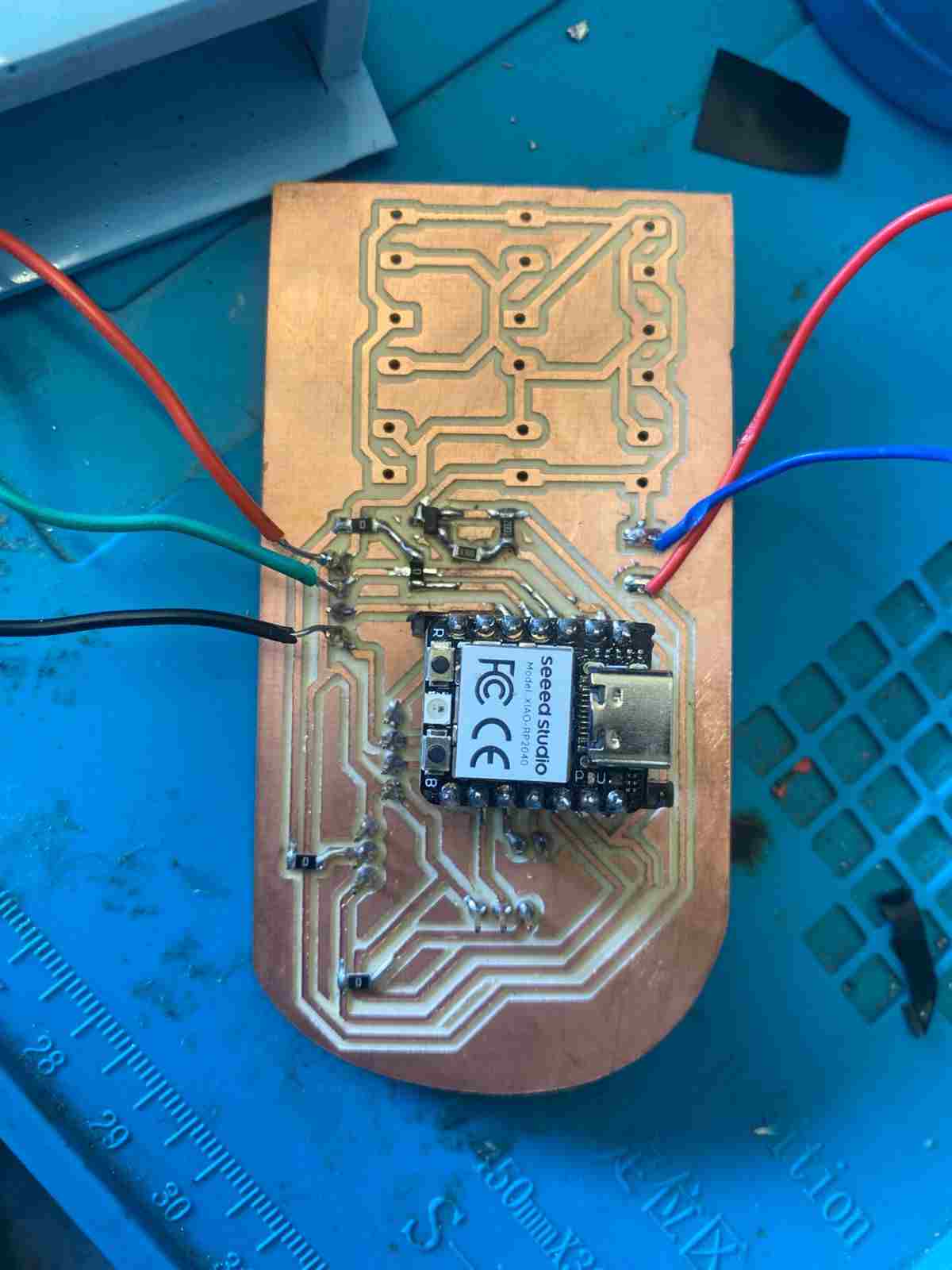
Main Board
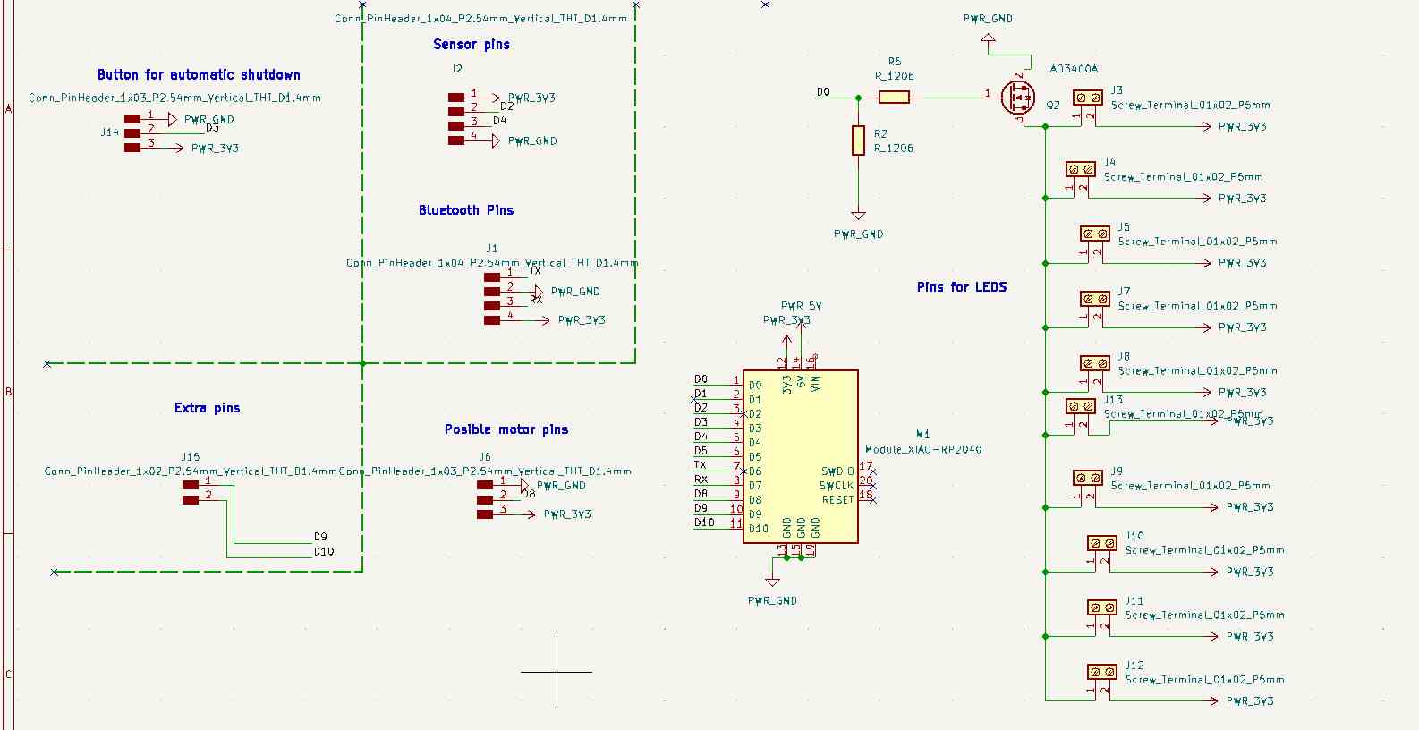
The schematic contains:
- A MOSFET controls all the LEDs. I added 10 terminals but only used one, as the other nine connections are made with conductive thread.
- Pinout for the sensor; in this case, I’m using an analog input.
- Extra pins for additional components like a vibration motor, Bluetooth module, and button.
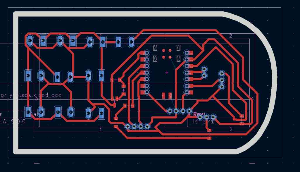
In the PCB design, I used 0-ohm resistors as bridges.
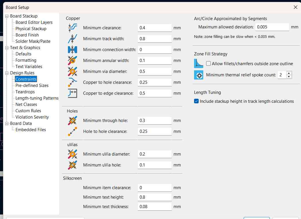
Parameters and desing rules checker
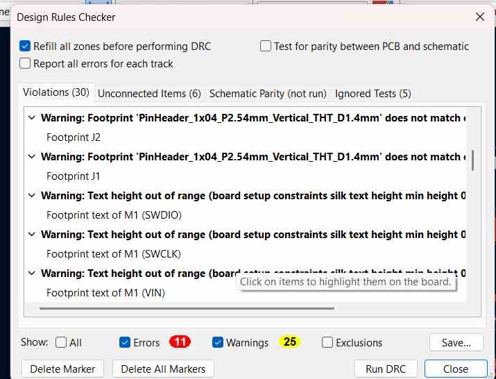
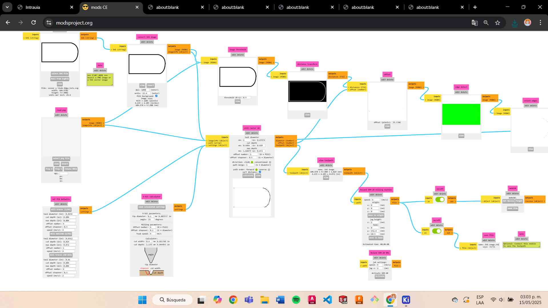
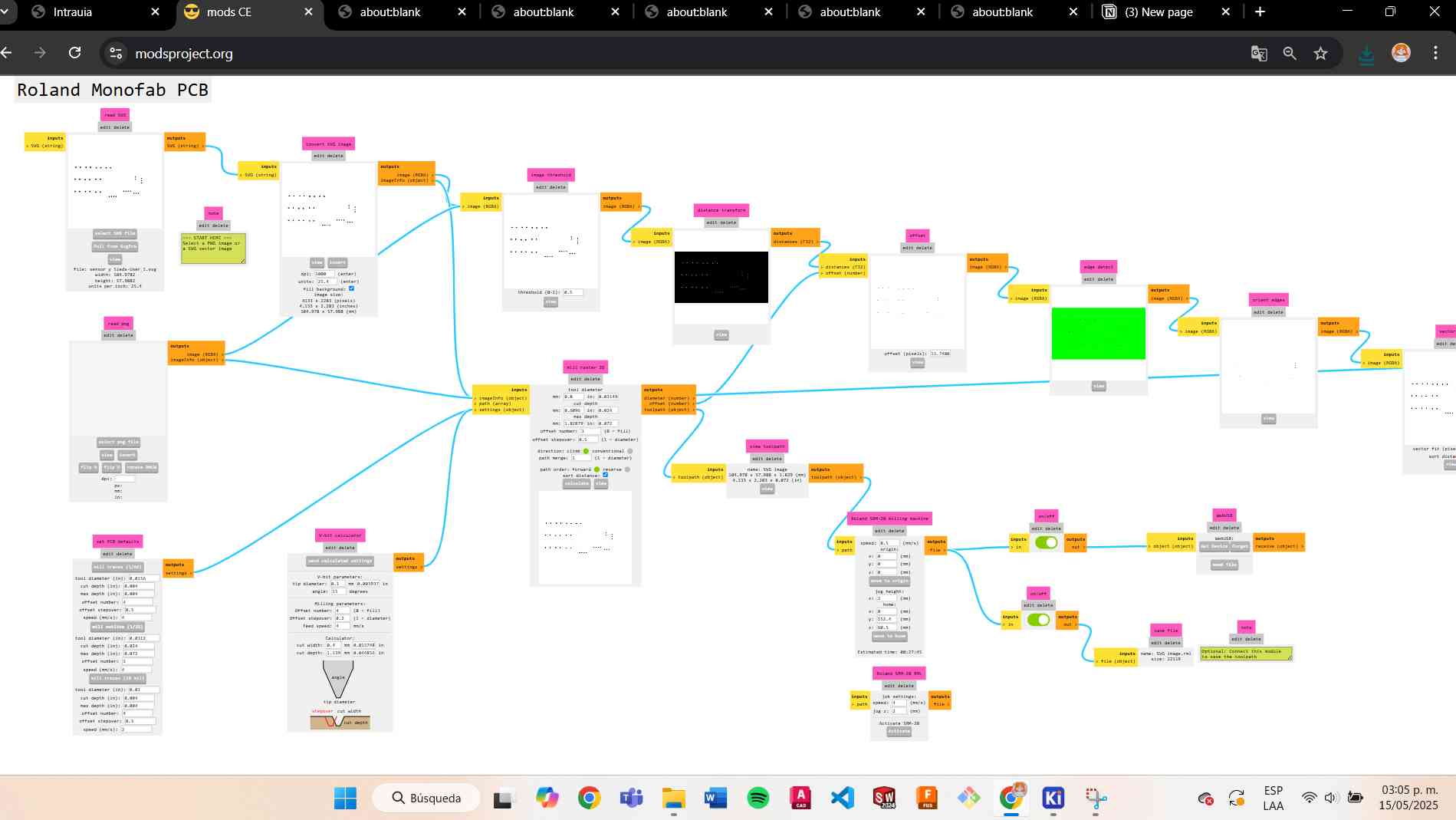
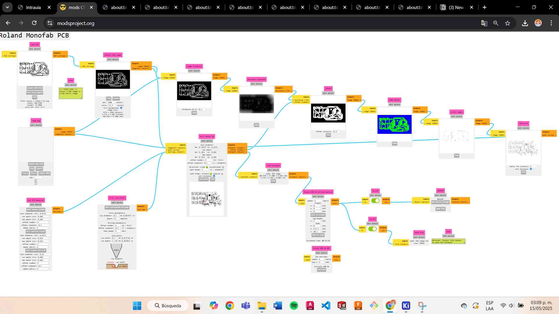
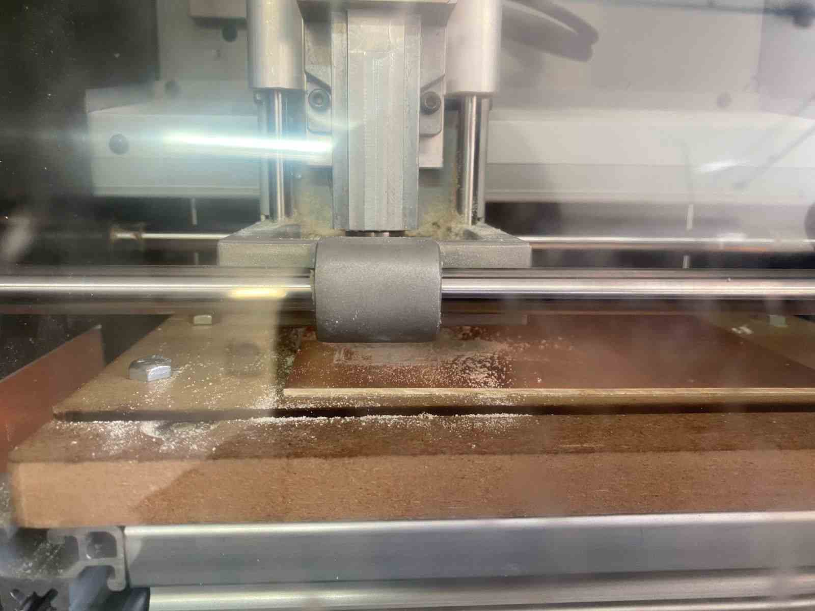
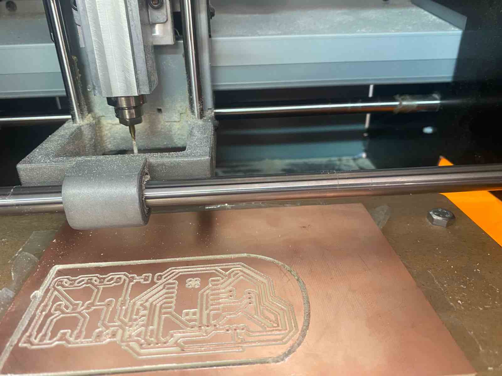
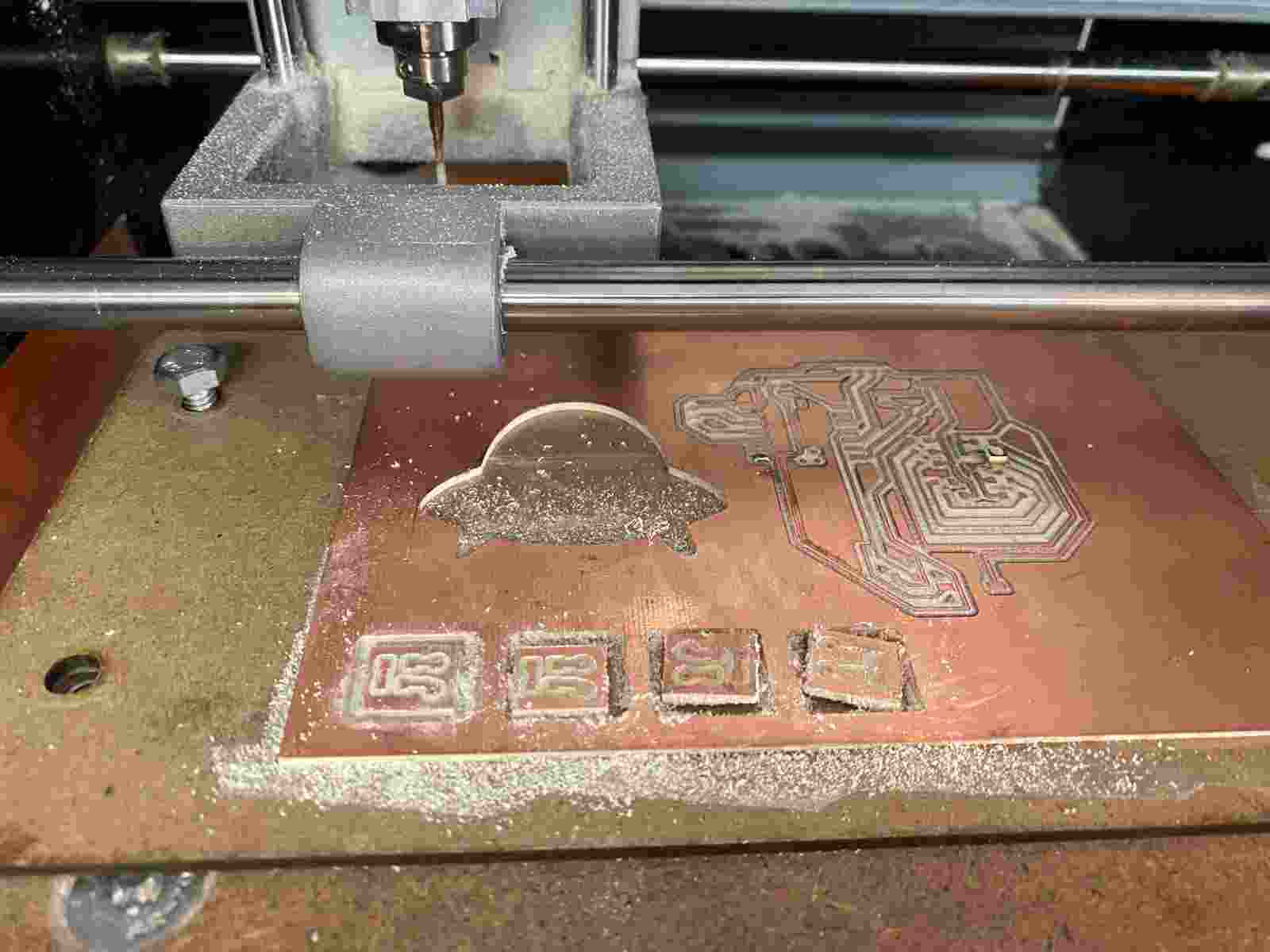
Processes
The tools I used were:
- Engraving: V-shaped tool
- Hole cutting: 0.8 mm tool
- Edge cutting: 2 mm tool
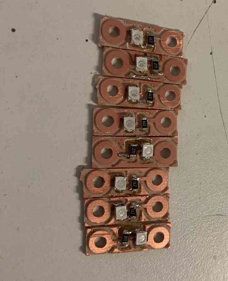
Leds PCB
On the inside part, I decided to create a module where I added the LEDs, similar to Lilypad modules.
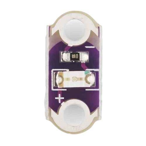
I fabricated several modules and began placing them on the vest to create the desired lighting effect.
White leds PCB
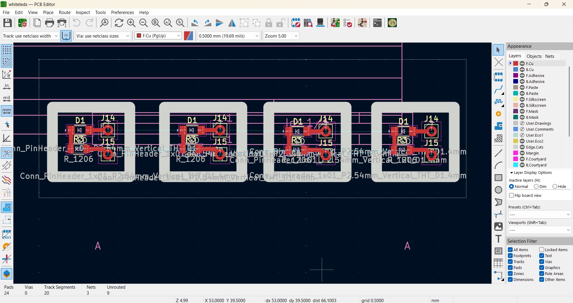
Interface and programming
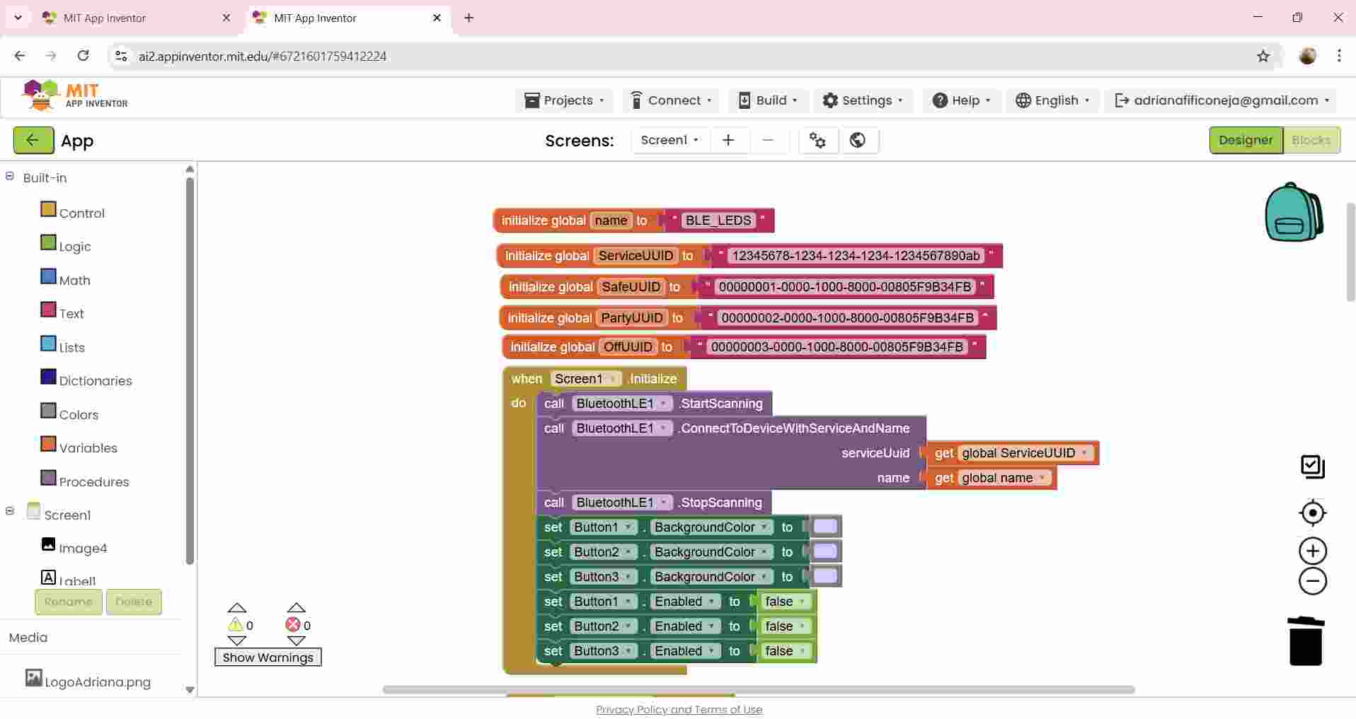
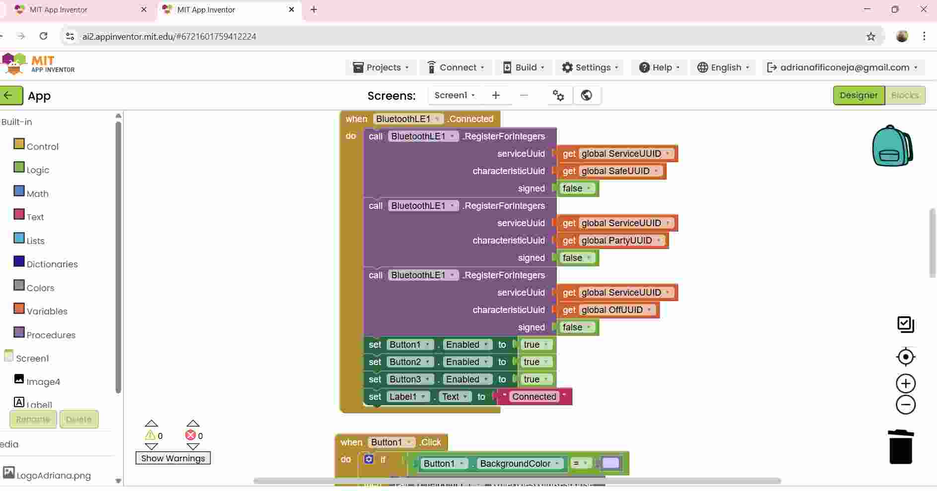
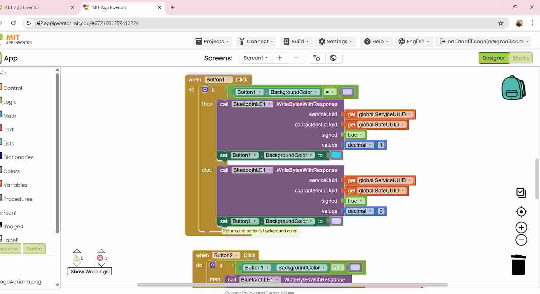
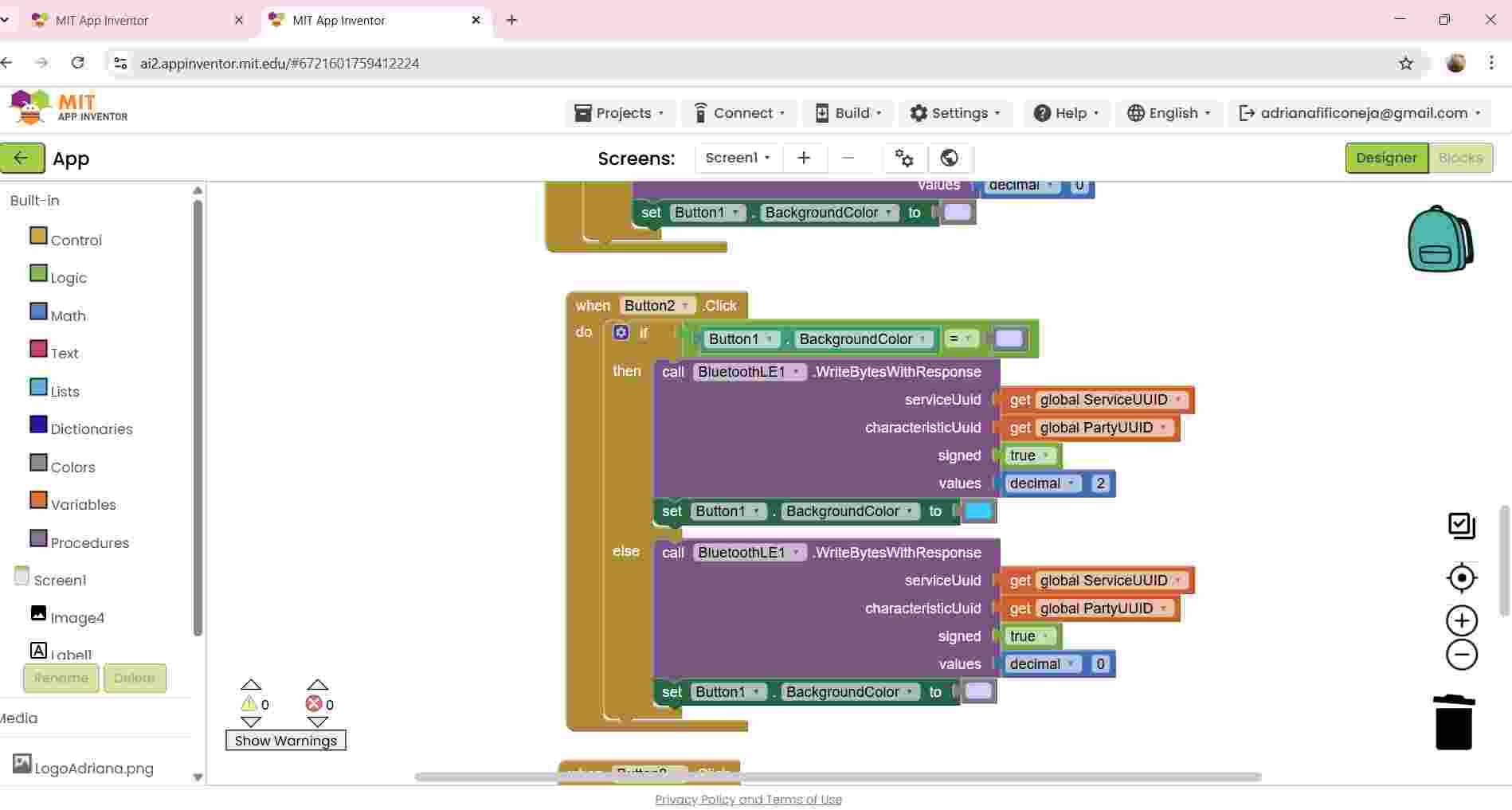
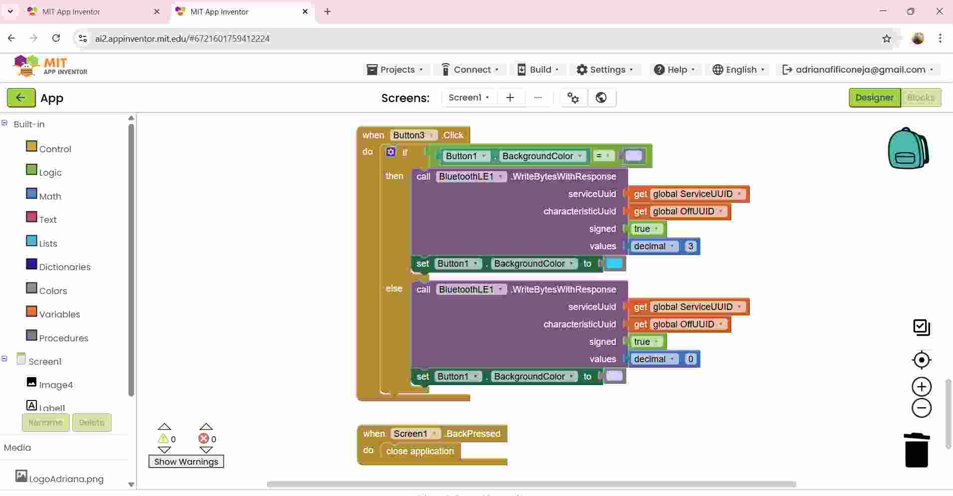
These are the blocks that I used.
First, I started by designing the interface. I added images, buttons, text, and Bluetooth functionality. In this case, I used BLE because my XIAO ESP32-C6 supports BLE.
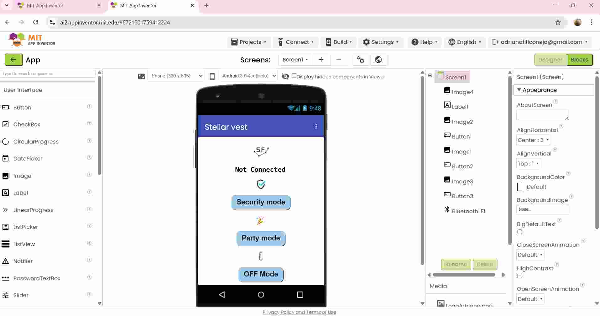
First, I started by adding the name of the global variable, which in this case will be the name of the device to connect to. The other global variable is related to each button. Then, I added a variable that indicates that when the screen opens, the device will start scanning for Bluetooth and attempt to connect using the service UUID and device name. The buttons are purple by default, but when pressed, they change color and update the global characteristic to perform different actions. There are three buttons that perform three different actions:
- Security mode: Turns on the LEDs when a person is close.
- Party mode: Keeps the LEDs on continuously.
- Off mode: Turns off the LEDs and the sensor.
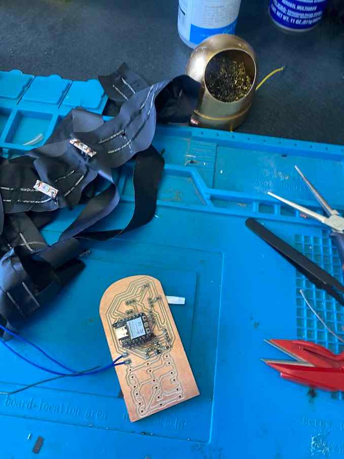
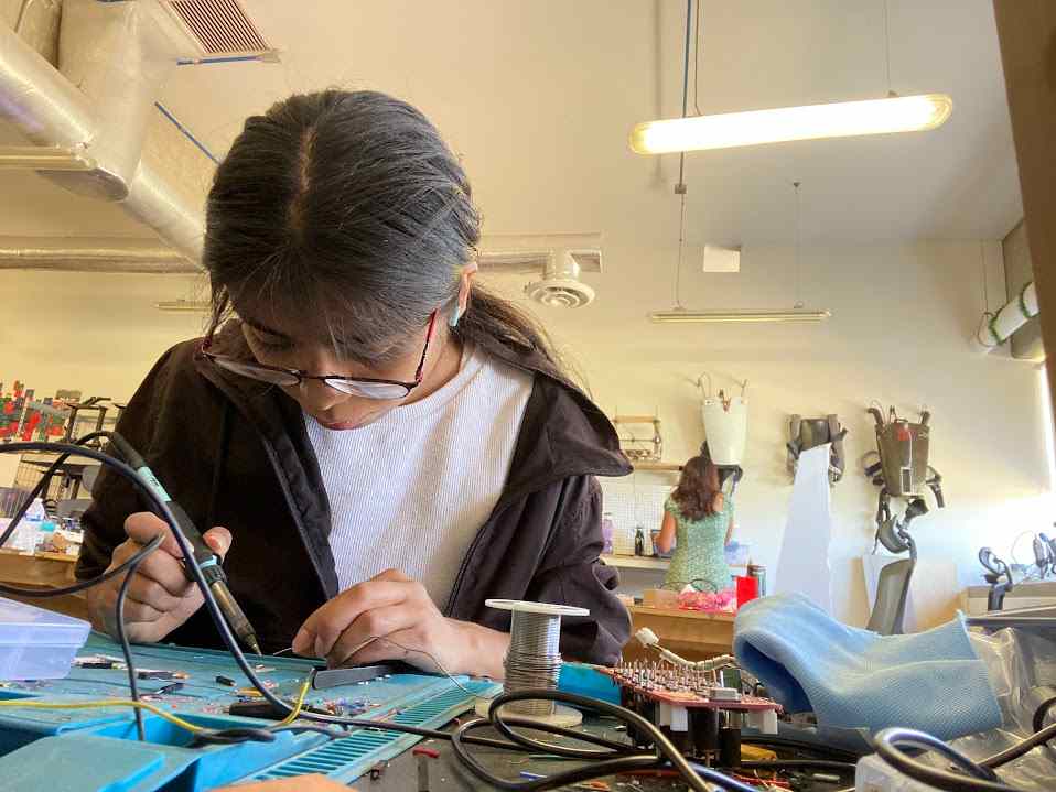
Process of soldering
Questions
What does it do?
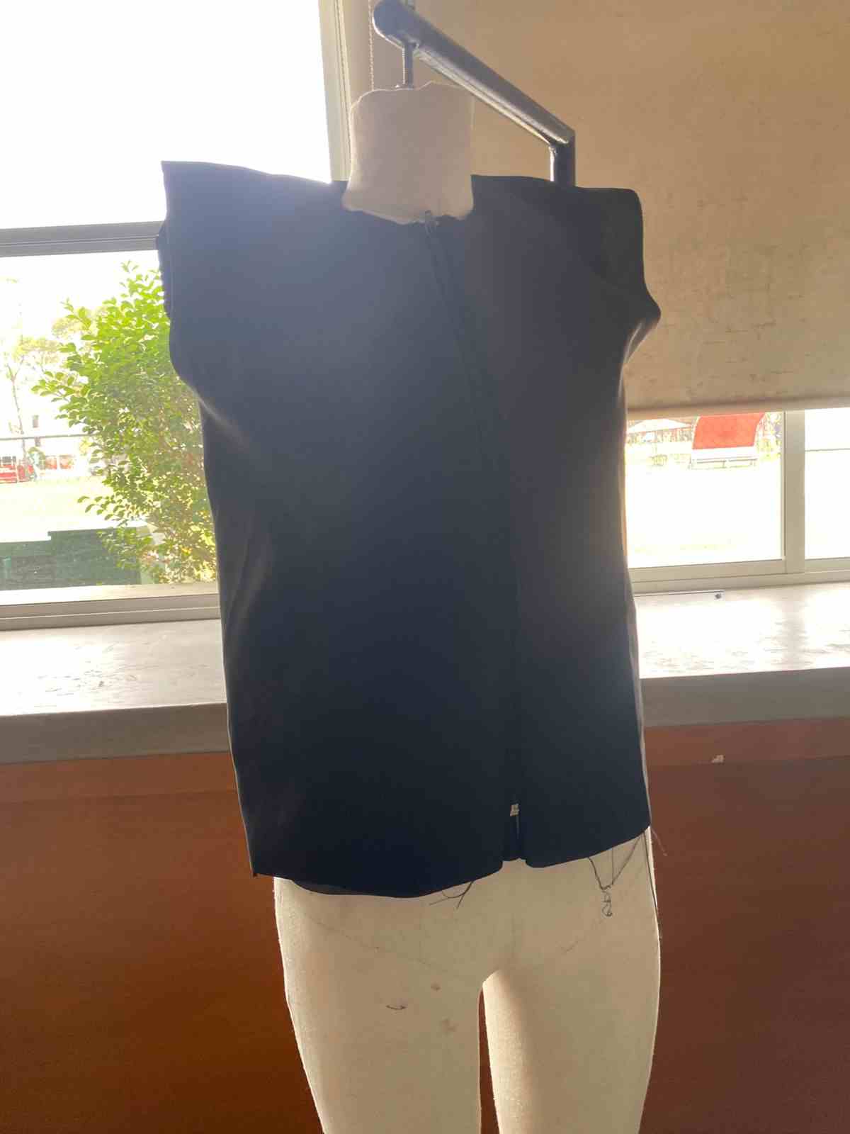
I maked a vest with the following features:
- The vest will protect people at night.
- The vest is very practical because it will be easy to put on and take off.
- The vest have LED lights and optical fiber.
Who's done what beforehand?
I reviewed other related projects and found some that inspire mine.
In my research, I found a mirror with several features, one of which is that it contains a motion sensor, and when it detects movement, it lights up the mirror.
Another idea I found was this type of vest that protects people at night because it has integrated LED lights that make them visible.
What did you design?
- Patterns for the vest
- A PCB and LED module designs
- The mold design for the sensor and the case for the main PCB
Material List
| Product | Quantity | Mexican pesos | Dollars | Store | Link |
|---|---|---|---|---|---|
| XIAO ESP32 C6 | 1 | 128.00 | 6.64 | Unit Electronics | [Link] |
| Thread | 6 | 174.00 | 9.03 | Unit Electronics | [Link] |
| Sensor LV-EZ0 MB1000 | 1 | 613.00 | 31.81 | Amazon | [Link] |
| Rechargeable battery | 1 | 390.00 | 20.24 | Radio Shack | [Link] |
| Velcro | 1 | 36.00 | 1.87 | Hilos Lobo | [Link] |
| Black zipper | 1 | 6.00 | 0.31 | Hilos Lobo | [Link] |
| Fabric "Pinguino" | 1 | 89.00 | 4.62 | Deportextil | [Link] |
| Fabric "Kyoto" | 1.5 | 114.00 | 5.92 | Deportextil | [Link] |
| LEDs SMD | 10 | N/A | N/A | Fab Lab | |
| Resistors 1260 0Ω | 4 | N/A | N/A | Fab Lab | – |
| Resistors 1260 270Ω | 10 | N/A | N/A | Fab Lab | – |
| Resistors 1260 330Ω | 1 | N/A | N/A | Fab Lab | – |
| Resistors 1260 10kΩ | 1 | N/A | N/A | Fab Lab | – |
| MOSFET N 30V | 1 | N/A | N/A | Fab Lab | – |
| Female pins | 1 | N/A | N/A | Fab Lab | – |
| Phenolic plate | 1 | N/A | N/A | Fab Lab | – |
| Wire cable | 3 | N/A | N/A | Fab Lab | – |
| Total cost | $1,550.00 | $80.44 |
What parts and systems were made?
- 3D-printed case for the sensor
- PCB for the microcontroller and LED/resistor modules
- Molding and casting for the main PCB case
- Laser cutting for vest pattern and LED modules
- Vinyl cutting for the logo on the vest
What processes were used?
- 2D design
- 3D design
- 3D printing
- Laser cutting
- Vinyl cutting
- Electronics production (milling machine)
- Molding and casting
- Textile sublimation
- Interface and Application Programming
What questions were answered?
- How will I control the current to the LEDs?
I used a MOSFET to control the high-power LEDs from the microcontroller safely. I tested different wiring configurations and resistors to manage current properly and avoid damage to the components. - How can I make the vest washable?
Instead of trying to waterproof everything, I designed the electronics to be easily removable. The main board and components can be detached from the textile part, so the vest can be washed without risk. - How can I make the vest look futuristic without looking like a Christmas tree?
I combined blue LEDs with optical fiber and added white lights to create a subtle glow effect. The lighting is integrated into the design in a clean, minimal way, avoiding excess brightness or color overload.
What has worked? What hasn't?
What has worked:
- The analog reading of the ultrasonic sensor works consistently with the XIAO ESP32-C3 after adjusting the code for accurate distance measurement.
- The MOSFET successfully controls the LEDs without overheating or voltage drops.
- The electronics are completely detachable, which makes the vest washable and easy to maintain.
- The combination of optical fiber, blue LEDs, and white LEDs creates a clean and futuristic visual effect.
- The PCB case fits properly and protects the electronics during movement.
- The conductive thread connections are now stable after reinforcing them during sewing.
What didn't work at first (but was fixed):
- The sensor gave different distance readings with the new microcontroller, but this was solved by recalibrating and adapting the code.
- Some conductive thread connections had continuity issues, which were resolved by redoing and securing the stitches.
- Initial placement of the optical fiber caused weak light transmission, but this was corrected by repositioning and reducing bending.
How was it evaluated?
- The sensor must detect at a proper distance.
- The LEDs should turn on when the sensor detects movement.
- The module must be well integrated, avoiding short circuits in the conductive thread.
- The vest must be controlled by Bluetooth
What are the implications?
This project aims to increase personal safety by improving visibility during nighttime. The vest uses LED lights and optical fibers to make the wearer more visible in low-light conditions, helping to prevent accidents and improve awareness from others such as drivers or pedestrians.
By creating a wearable that is both functional and comfortable, the project encourages people to use safety clothing without sacrificing style. The detachable electronics also make it practical for everyday use and easy maintenance.
This approach could contribute to the development of wearable safety devices for runners, cyclists, or anyone who needs to be visible at night. It highlights how wearable technology can have real, positive impacts on health and safety.
I want to thank Gerardo Mora Aquino and Maximo A. Figueroa-Navarro to help me with electronics issues.
Conclusion
I learned how to solve problems, manage my time, and understand how inputs and outputs work. Throughout the process, I also improved my ability to document my work, plan ahead, and adapt when things didn’t go as expected. I became more comfortable working with microcontrollers, sensors, and different programming environments. In addition, I learned how to combine technical and creative thinking—especially when designing wearable technology that is both functional and meaningful. This project helped me gain confidence in working with electronics, digital fabrication tools, and integrating them into real-world applications. It also taught me the value of collaboration, iteration, and being patient with the learning process.