16.System integration
Material List
| Product | Quantity | Mexican pesos | Dollars | Store |
|---|---|---|---|---|
| XIAO ESP32 C6 | 1 | 128.00 | 6.64 | Unit Electronics |
| Thread | 6 | 174.00 | 9.03 | Unit Electronics |
| Sensor LV-EZ0 MB1000 | 1 | 613.00 | 31.81 | Amazon |
| Rechargeable battery | 1 | 390.00 | 20.24 | Radio Shack |
| Velcro | 1 | 36.00 | 1.87 | Deportextil |
| Black zipper | 1 | 6.00 | 0.31 | Deportextil |
| Fabric "Pinguino" | 1 | 89.00 | 4.62 | Deportextil |
| Fabric "Kyoto" | 1.5 | 114.00 | 5.92 | Deportextil |
| LEDs SMD | 10 | N/A | N/A | Fab Lab |
| Resistors 1260 0Ω | 4 | N/A | N/A | Fab Lab |
| Resistors 1260 270Ω | 10 | N/A | N/A | Fab Lab |
| Resistors 1260 330Ω | 1 | N/A | N/A | Fab Lab |
| Resistors 1260 10kΩ | 1 | N/A | N/A | Fab Lab |
| MOSFET N 30V | 1 | N/A | N/A | Fab Lab |
| Female pins | 1 | N/A | N/A | Fab Lab |
| Phenolic plate | 1 | N/A | N/A | Fab Lab |
| Wire cable | 3 | N/A | N/A | Fab Lab |
| Total cost | $1,550.00 | $80.44 |
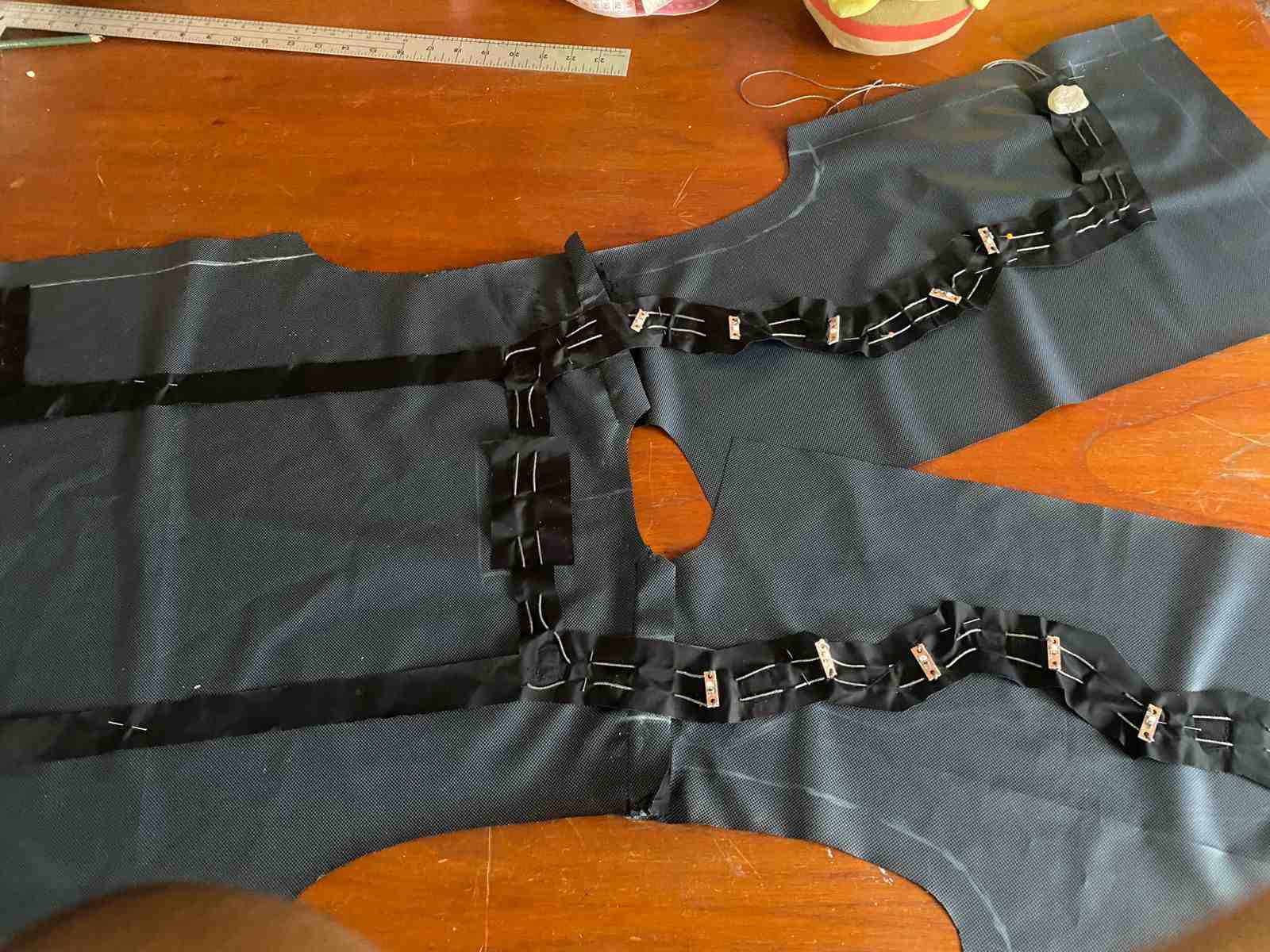
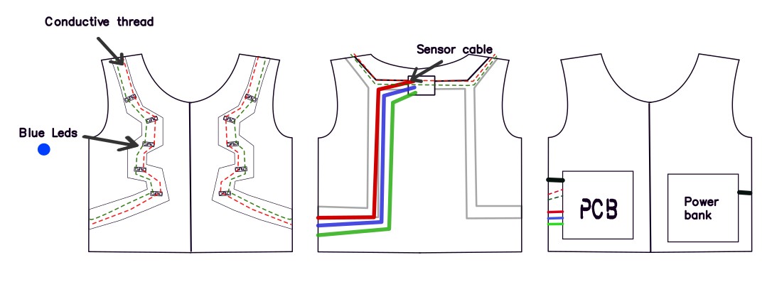
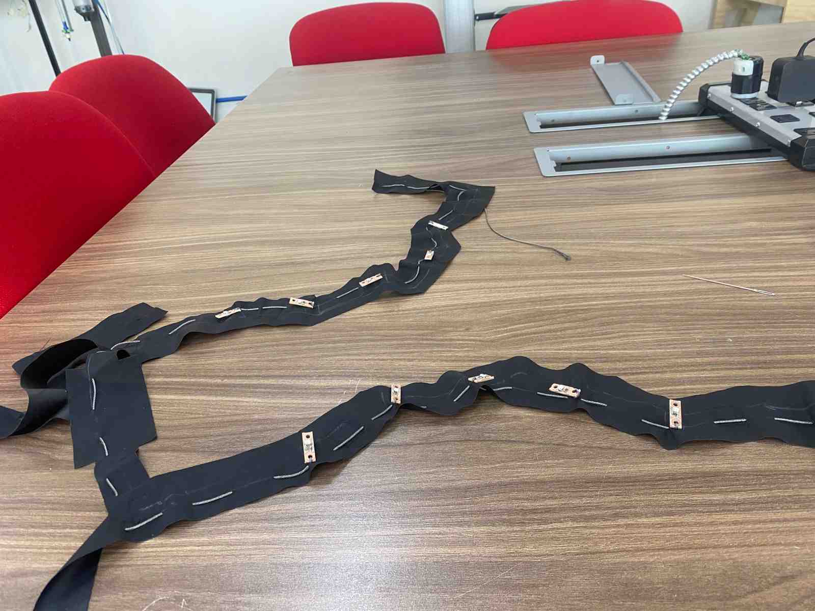
This is a graphic showing how I arranged the cables and the conductive thread. Everything is placed on the inside of the vest so that nothing is visible from the outside. This makes it more comfortable and only the light from the LEDs is visible.
implemented methods of packaging

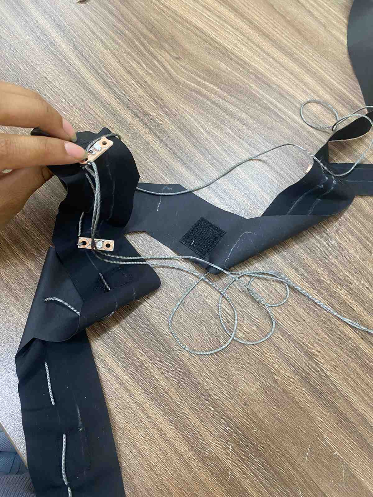
Integration with the LEDs
I used conductive thread to connect the LEDs. This method is more comfortable when someone wears the vest.
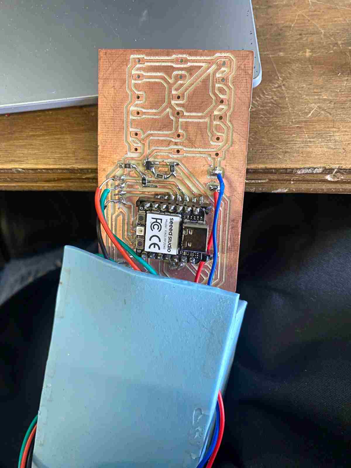
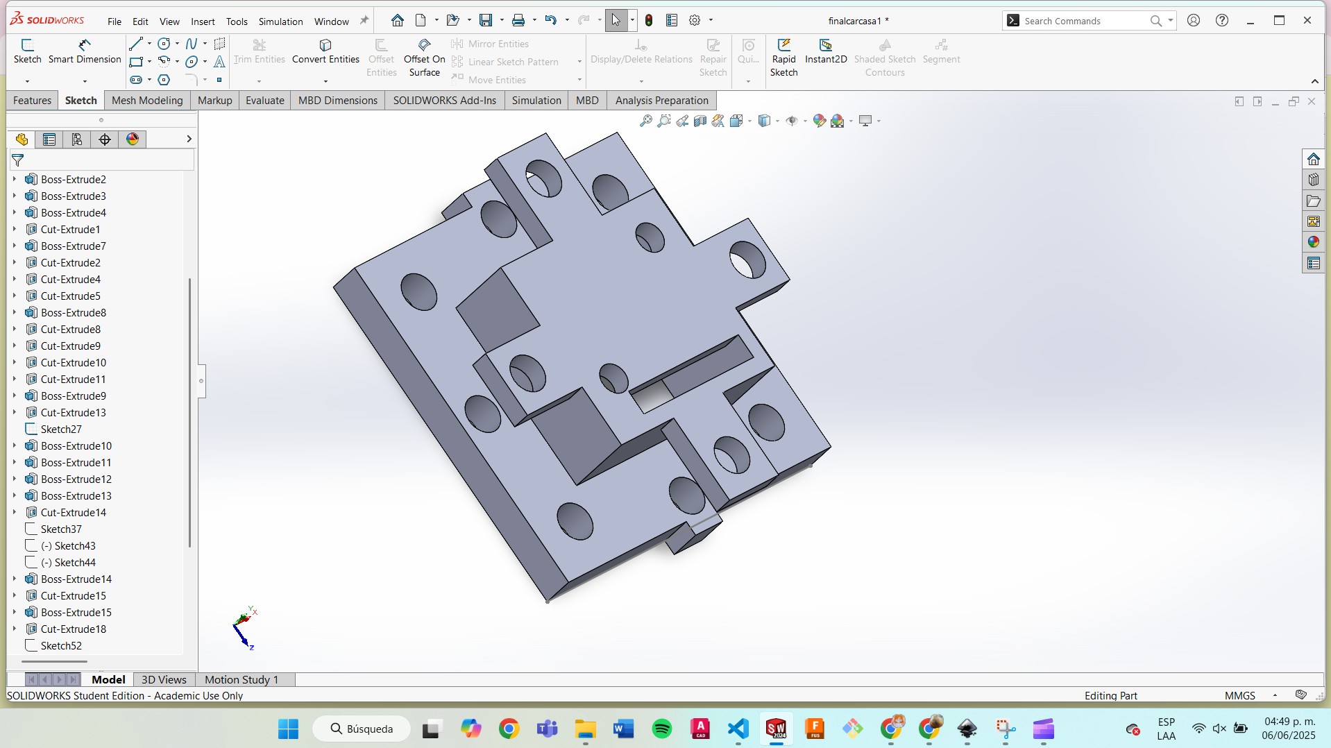
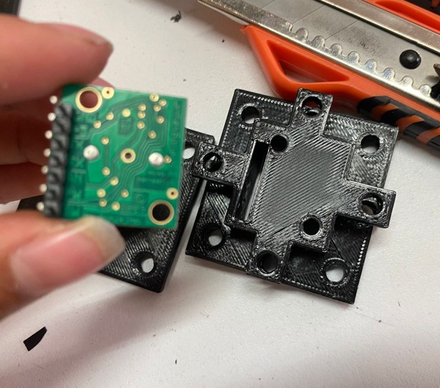
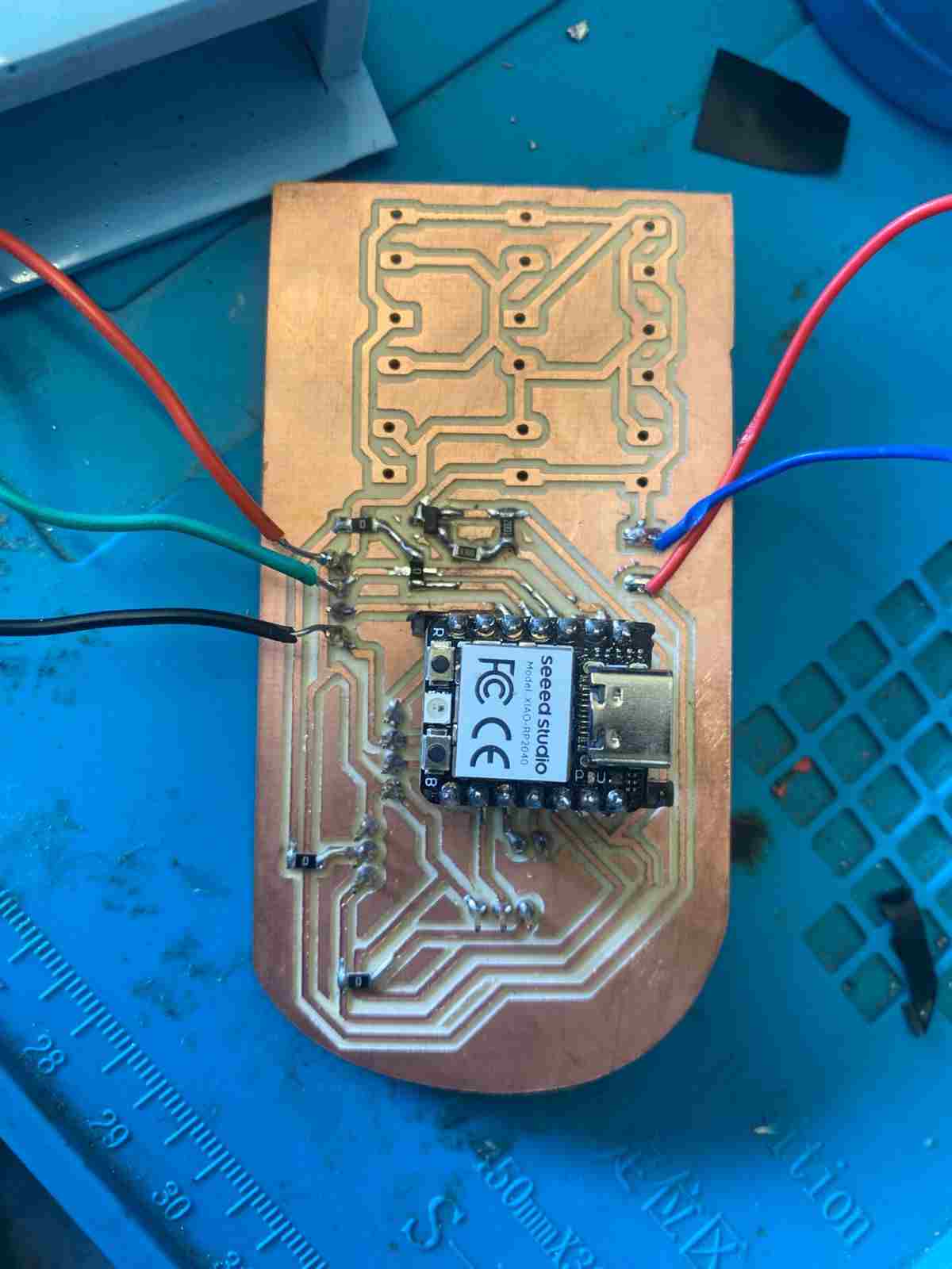
Integration with the PCB
The PCB is placed on the inside of the vest.
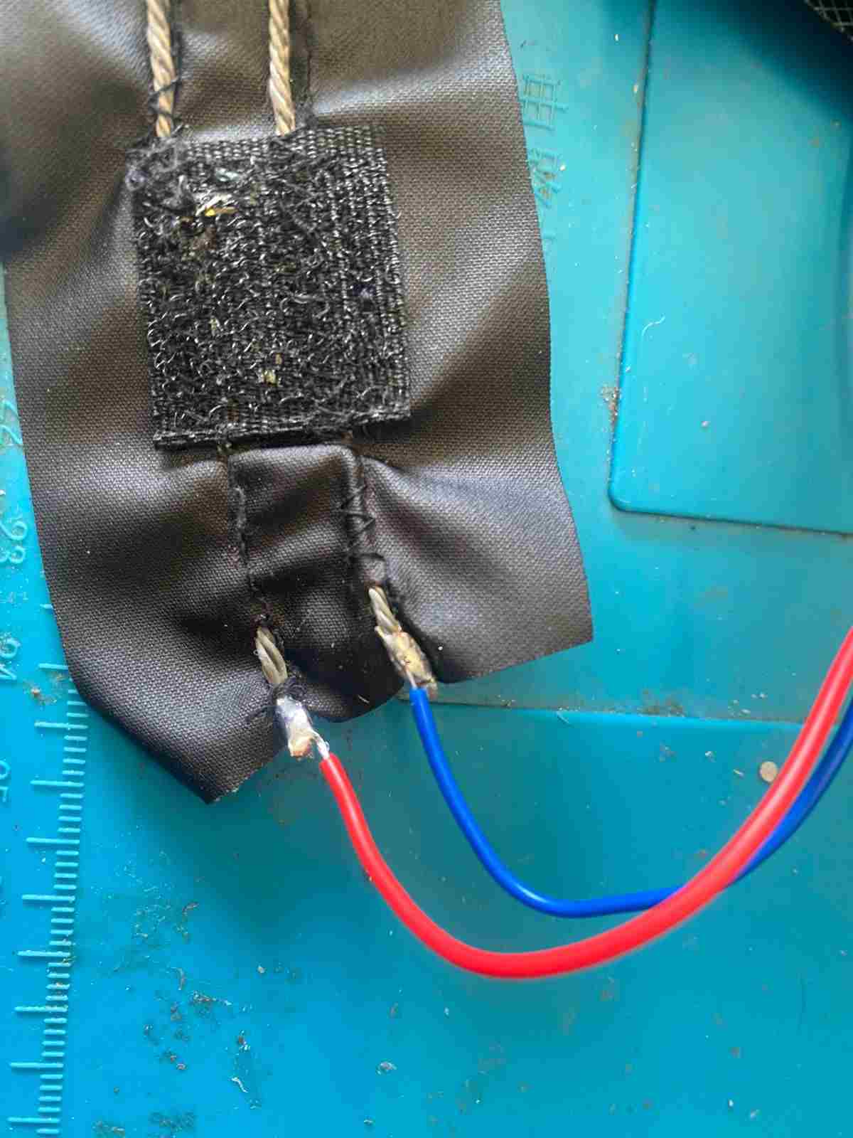
- I soldered all the cables. I couldn't use conductive thread in this case because all of them would be in contact, which could cause short circuits. So, I used cable on the PCB and then soldered it with the conductive thread. To solder it, I covered one end of the thread with conductive tape.
- I left some holes in case I want to add more LEDs later. They don’t affect the circuit and can work like antennas.
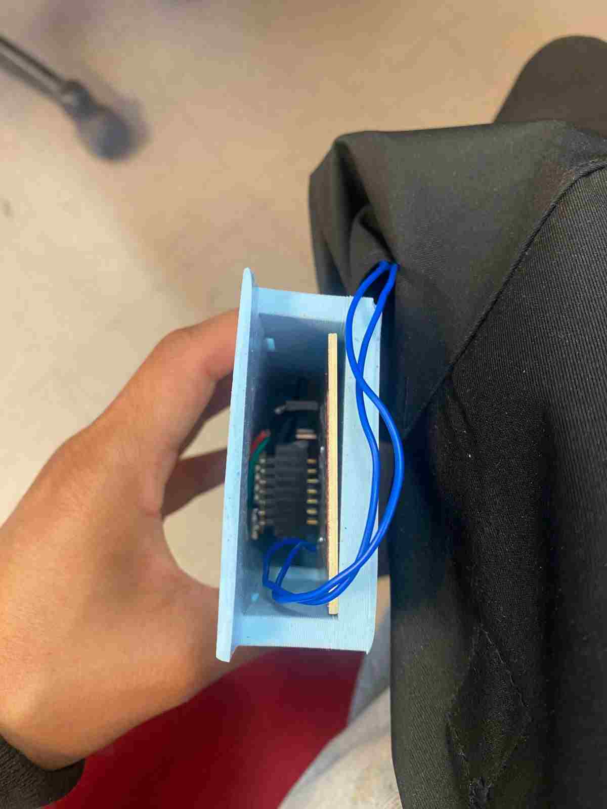
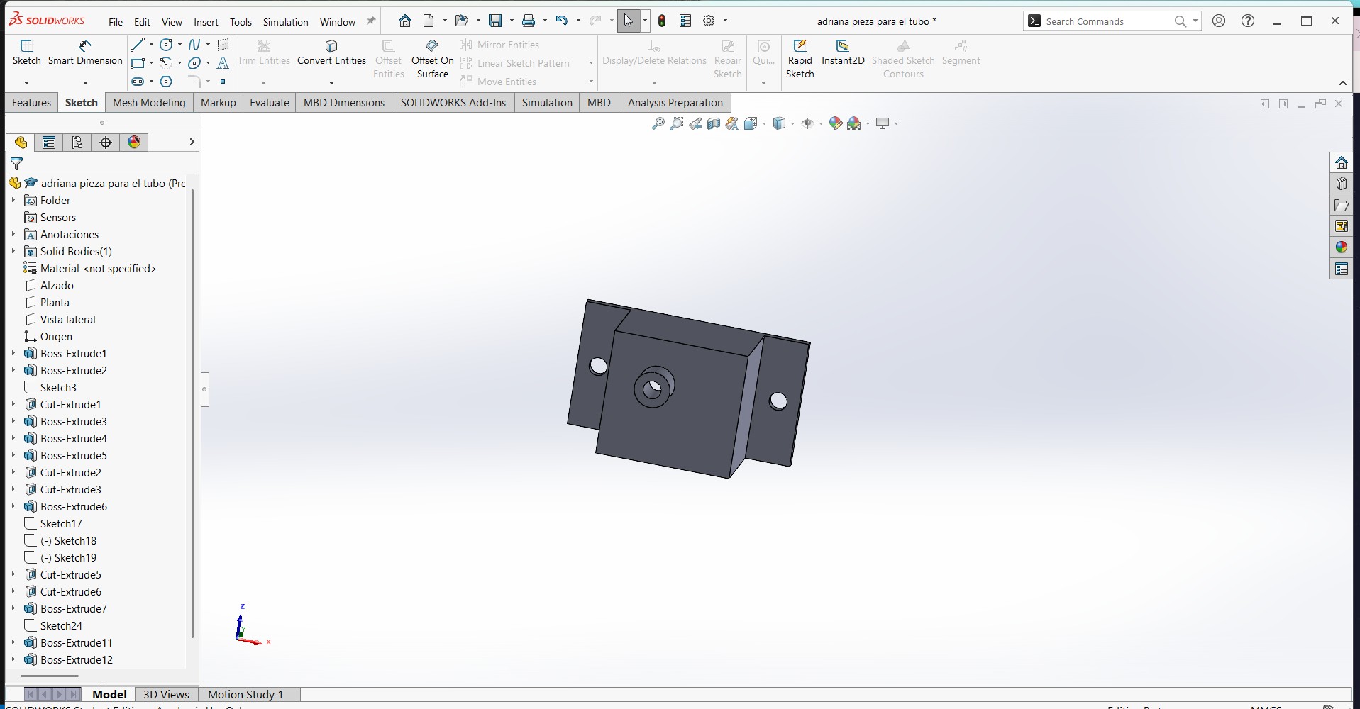
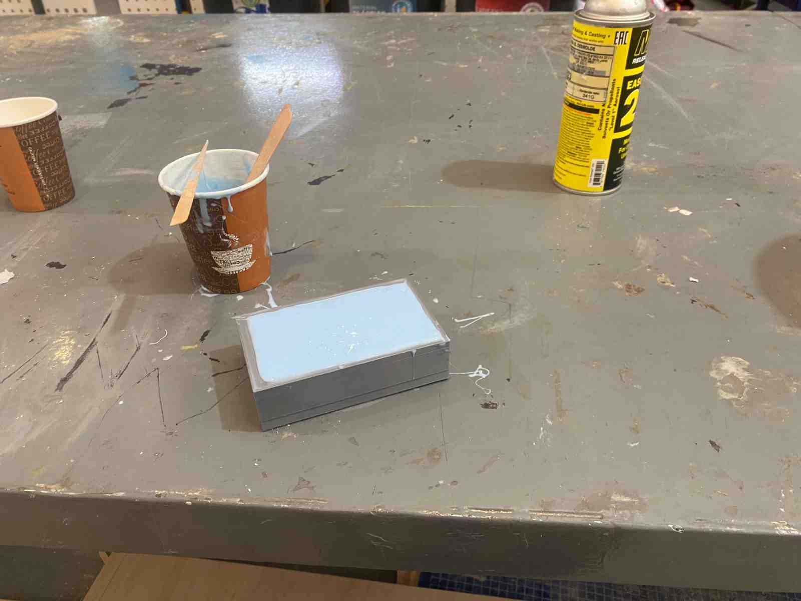
Case in the vest
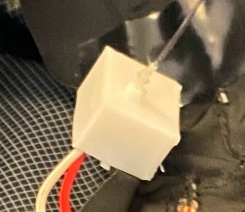
To protect the PCB, I made a silicone cover. I didn’t seal it completely so that air can circulate.
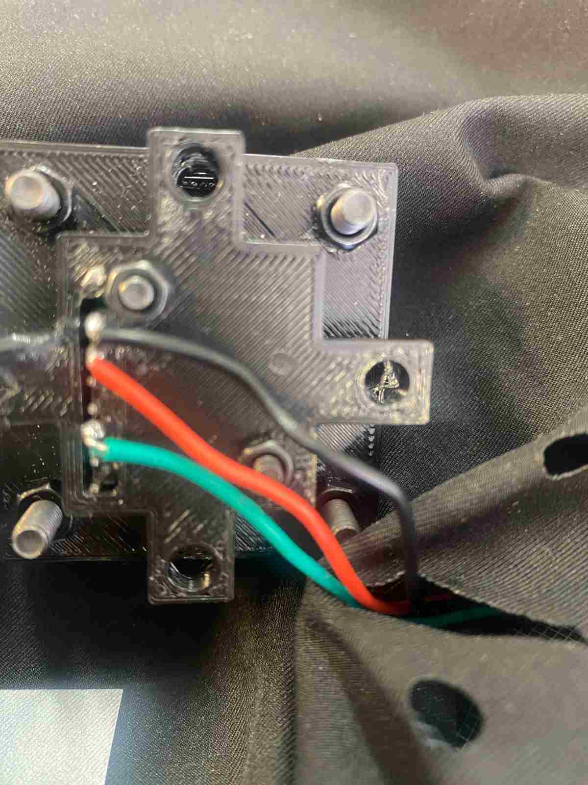
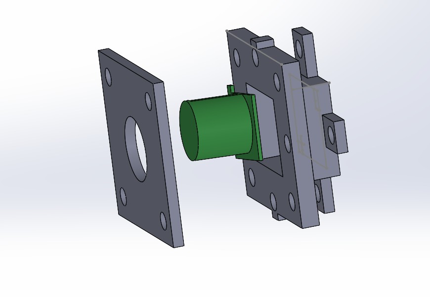
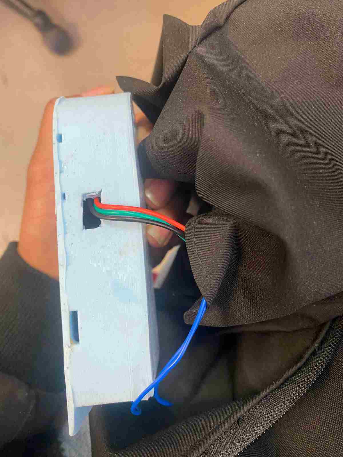
Integration of the Sensor
The way I connected the sensor is shown here. I left some holes in the back part of the vest to mount it.I used cables and placed them inside and at the back of the vest.
- To keep the sensor in a stable position and avoid false readings, I secured it tightly with screws.
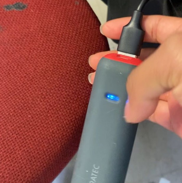
Battery Placement
I placed the battery in another pocket of the vest to keep the cables organized.
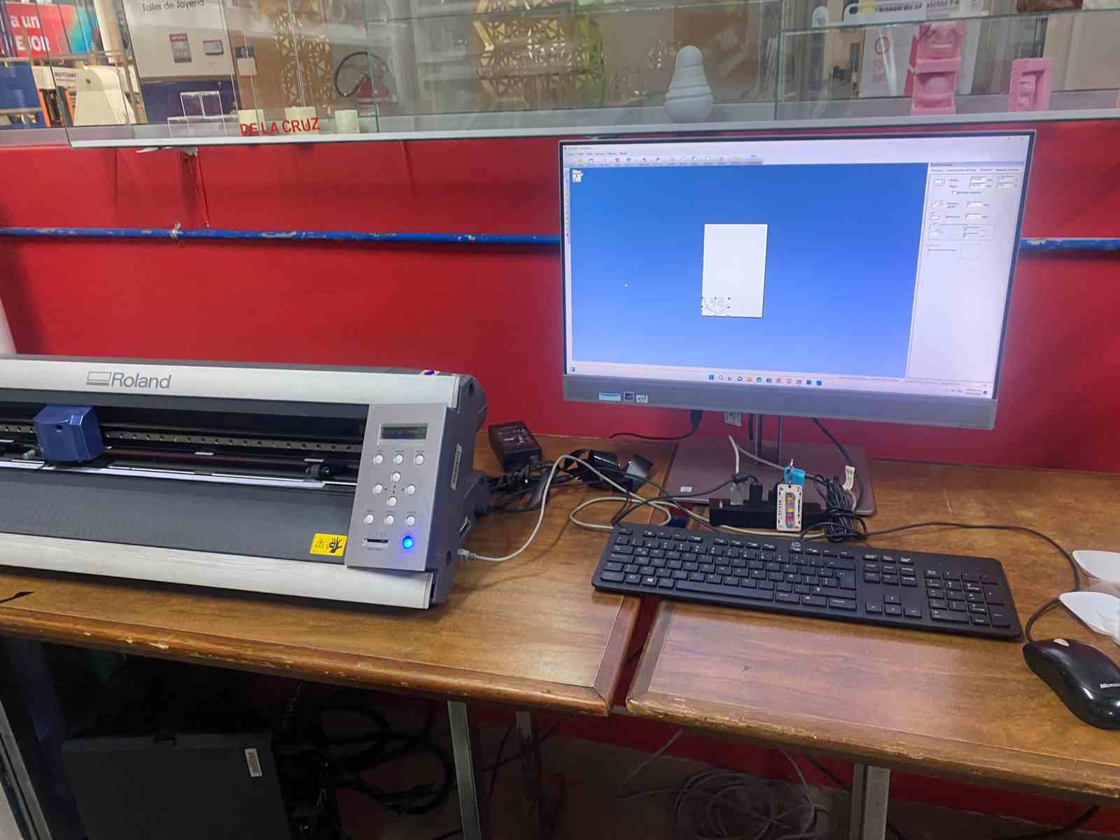
Electronics desing and production
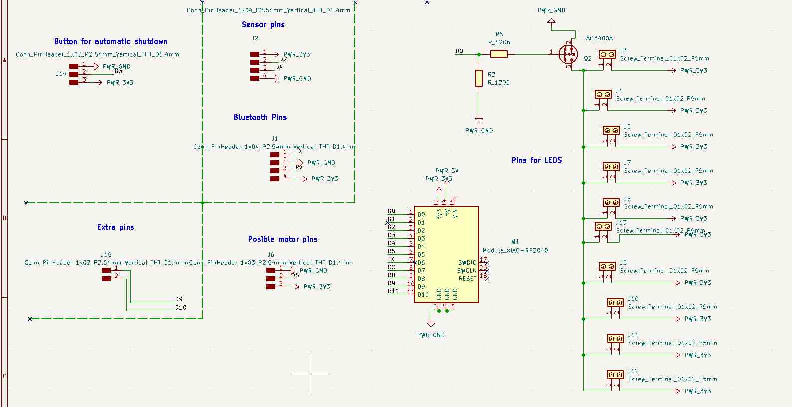
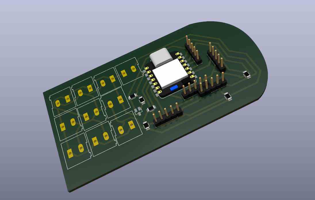
Main Board
The schematic contains:
- A MOSFET that controls all the LEDs. I added 10 terminals, but I only used 1 because the other 9 lines use conductive thread.
- Pinout for the sensor; in this case, I’m using an analog input.
- Extra pins for additional components like a vibration motor, Bluetooth module, and button.
In the PCB design, I used 0-ohm resistors as bridges.
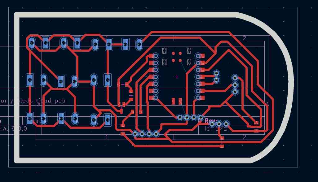
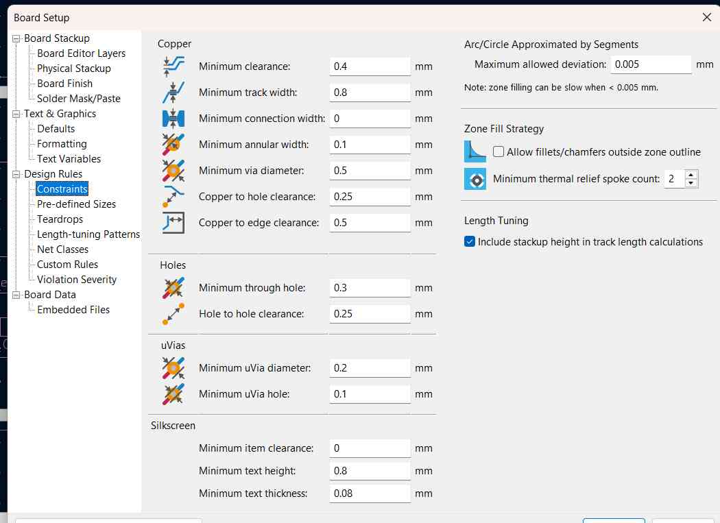
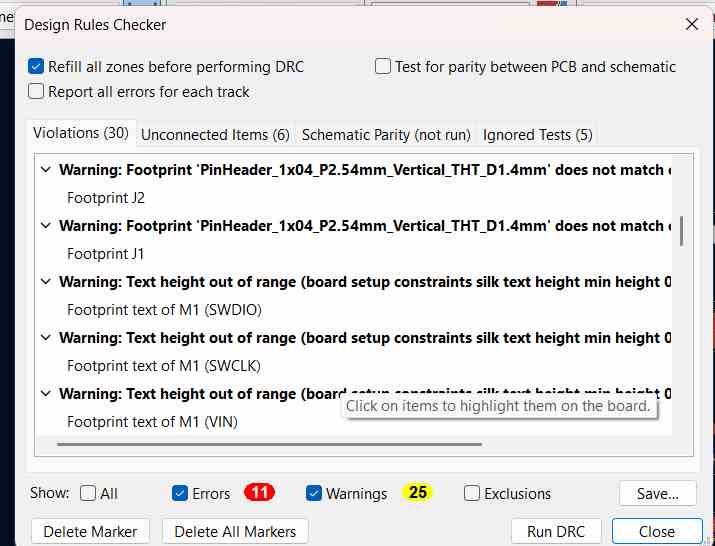
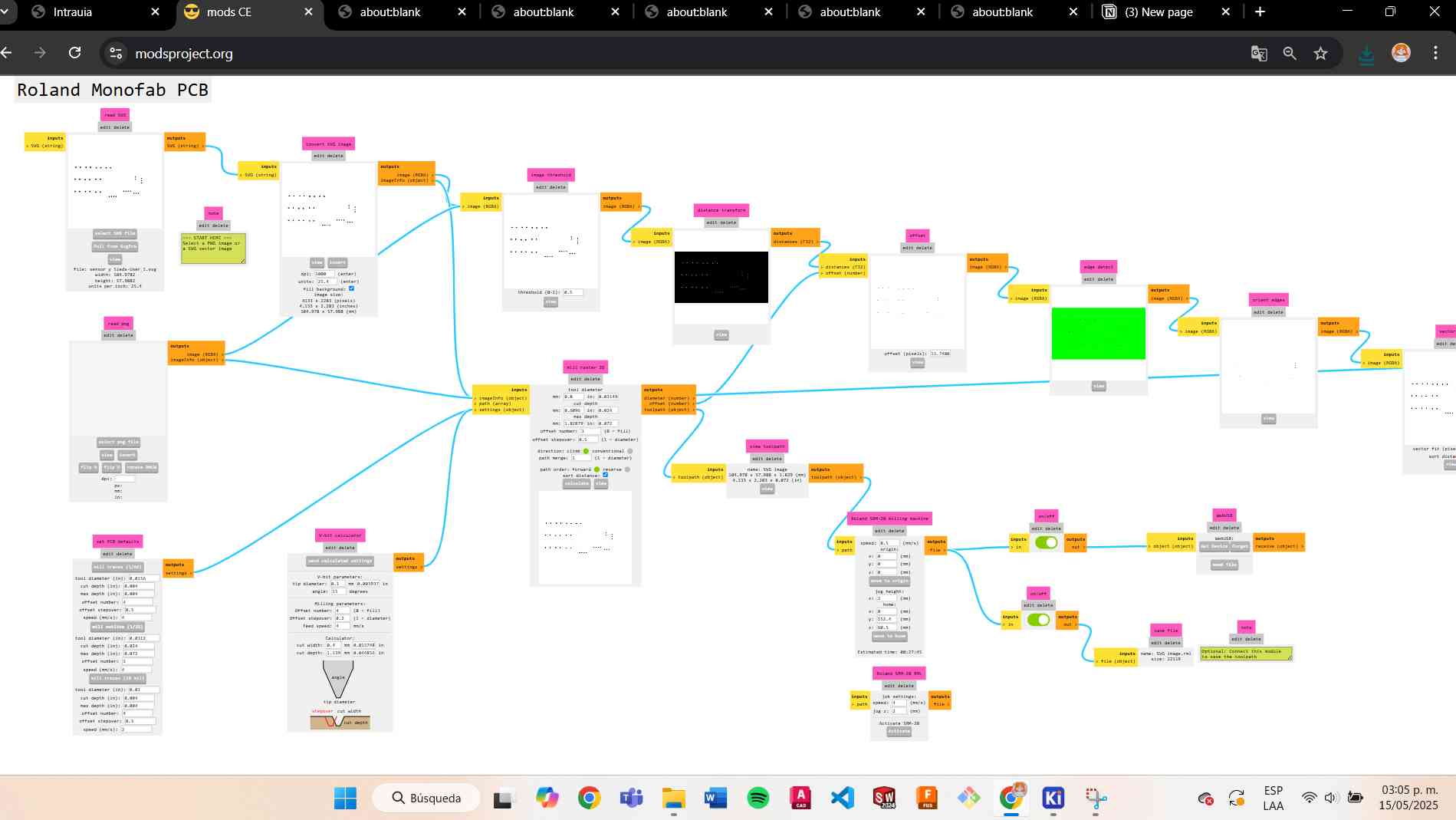
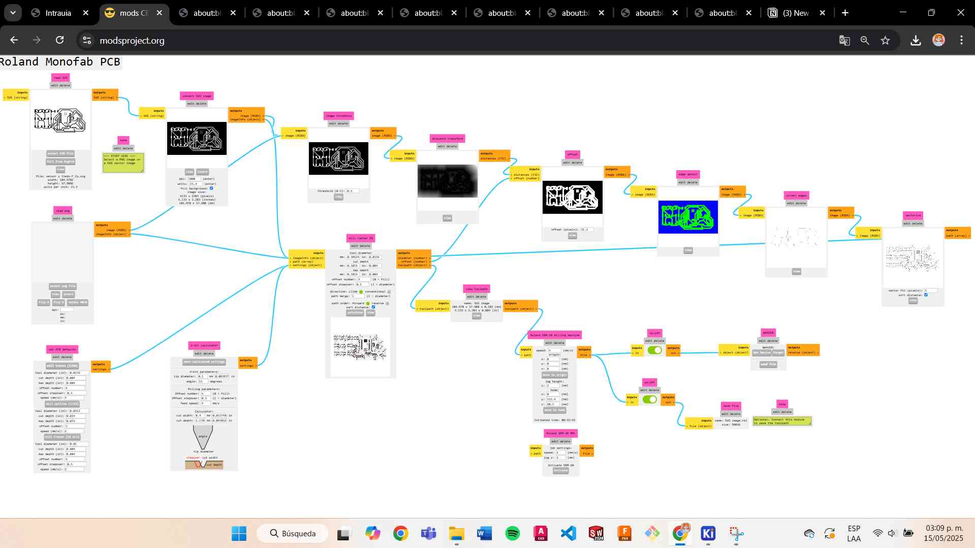
Parameters and desing rules checker
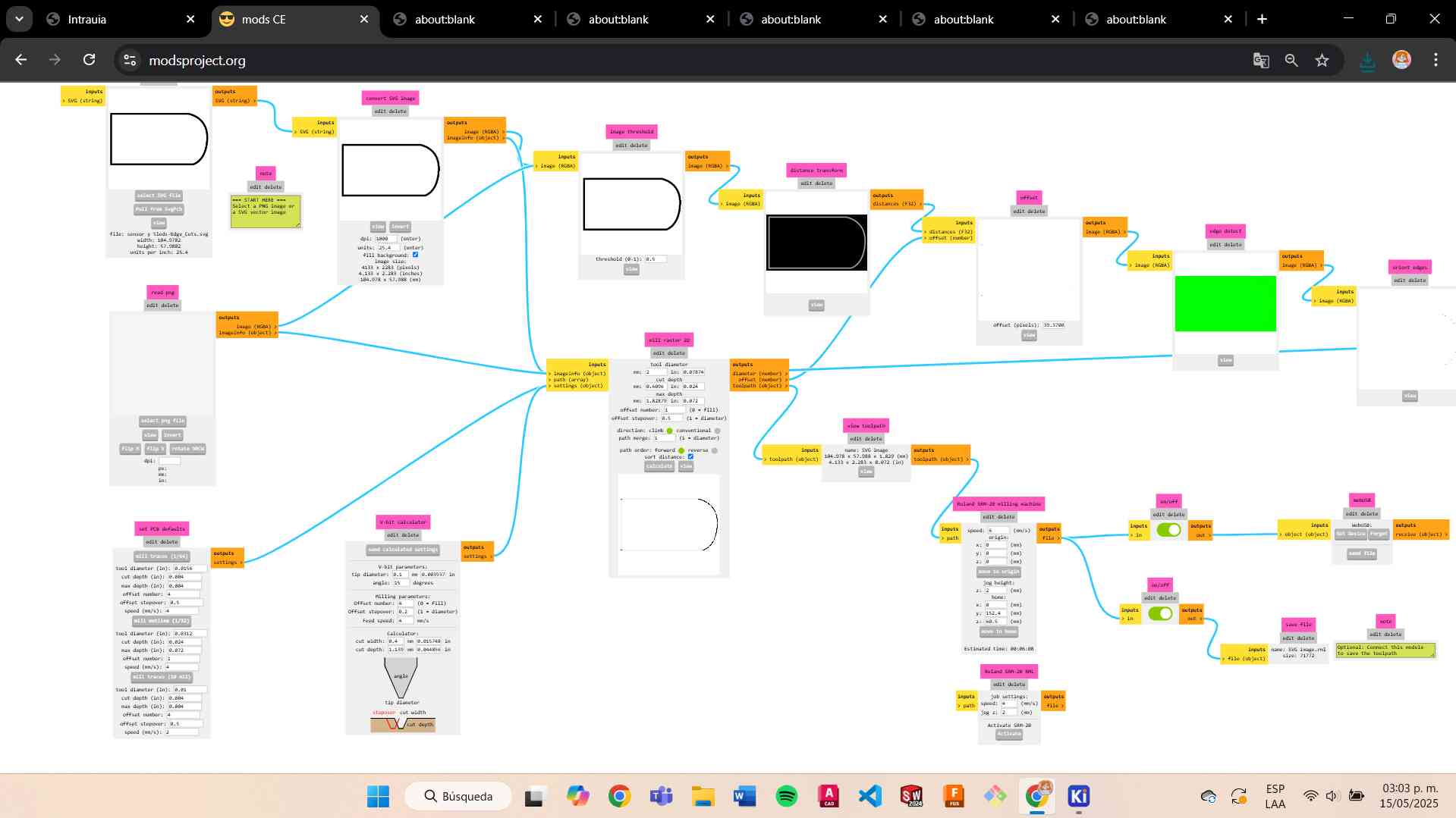
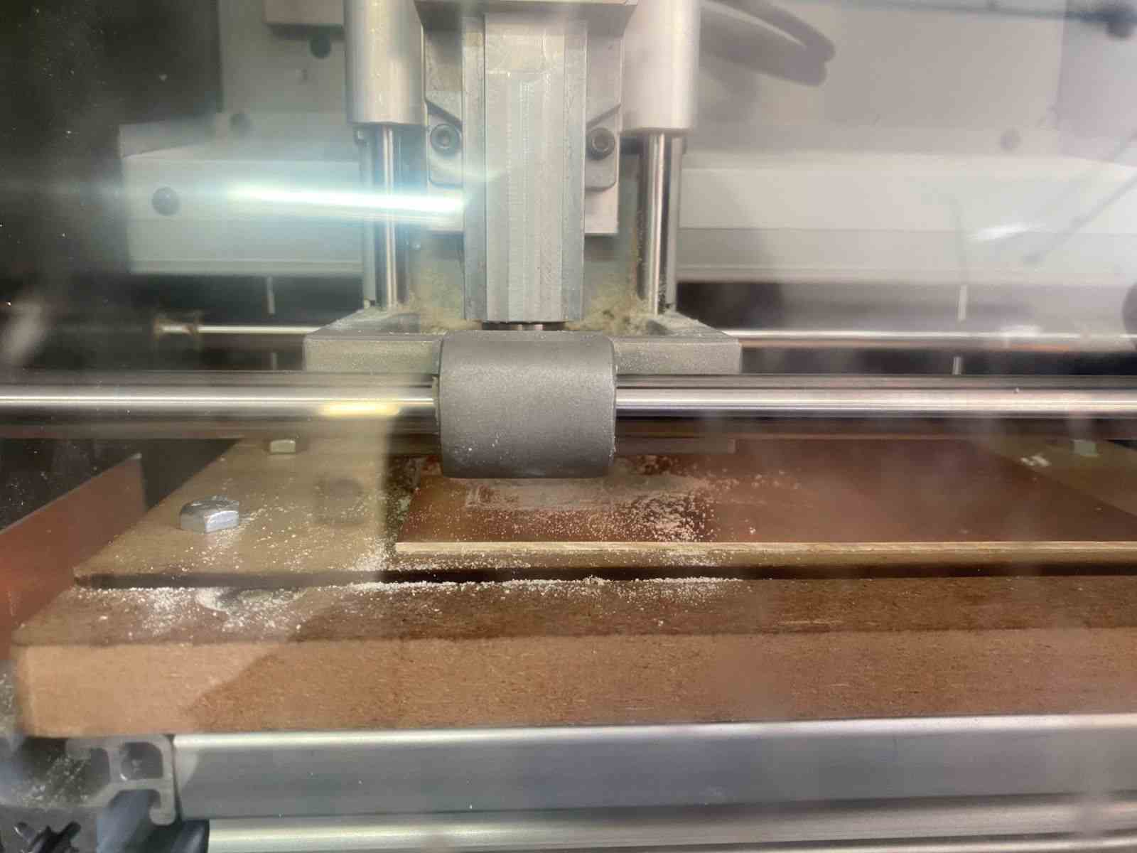
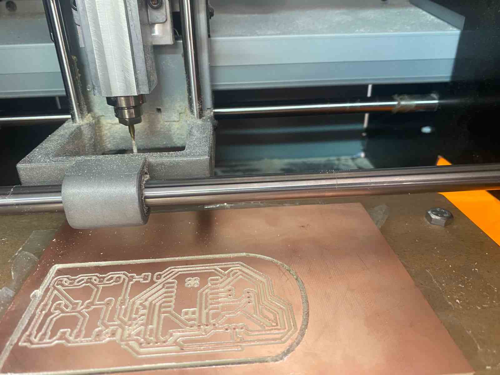
Processes
The tools I used were:
- Engraving: V-shaped tool
- Hole cutting: 0.8 mm tool
- Edge cutting: 2 mm tool
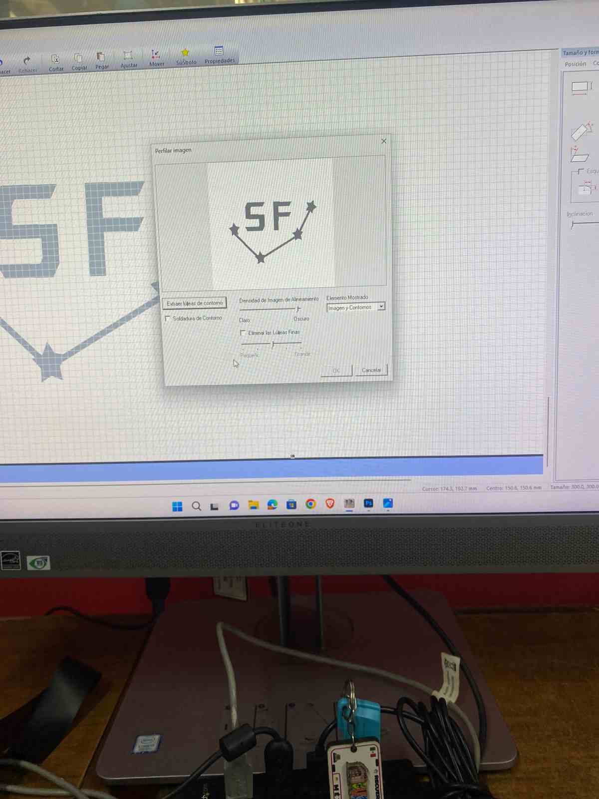
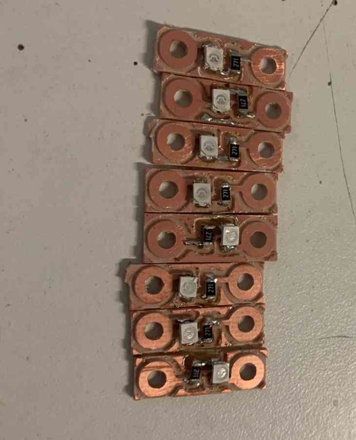
Leds PCB
On the inside part, I decided to create a module where I added the LEDs, similar to Lilypad modules.
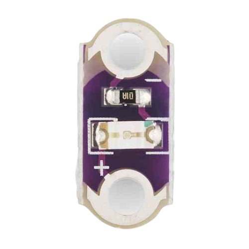
I fabricated some modules and started placing them on the vest to achieve the desired lighting effect.
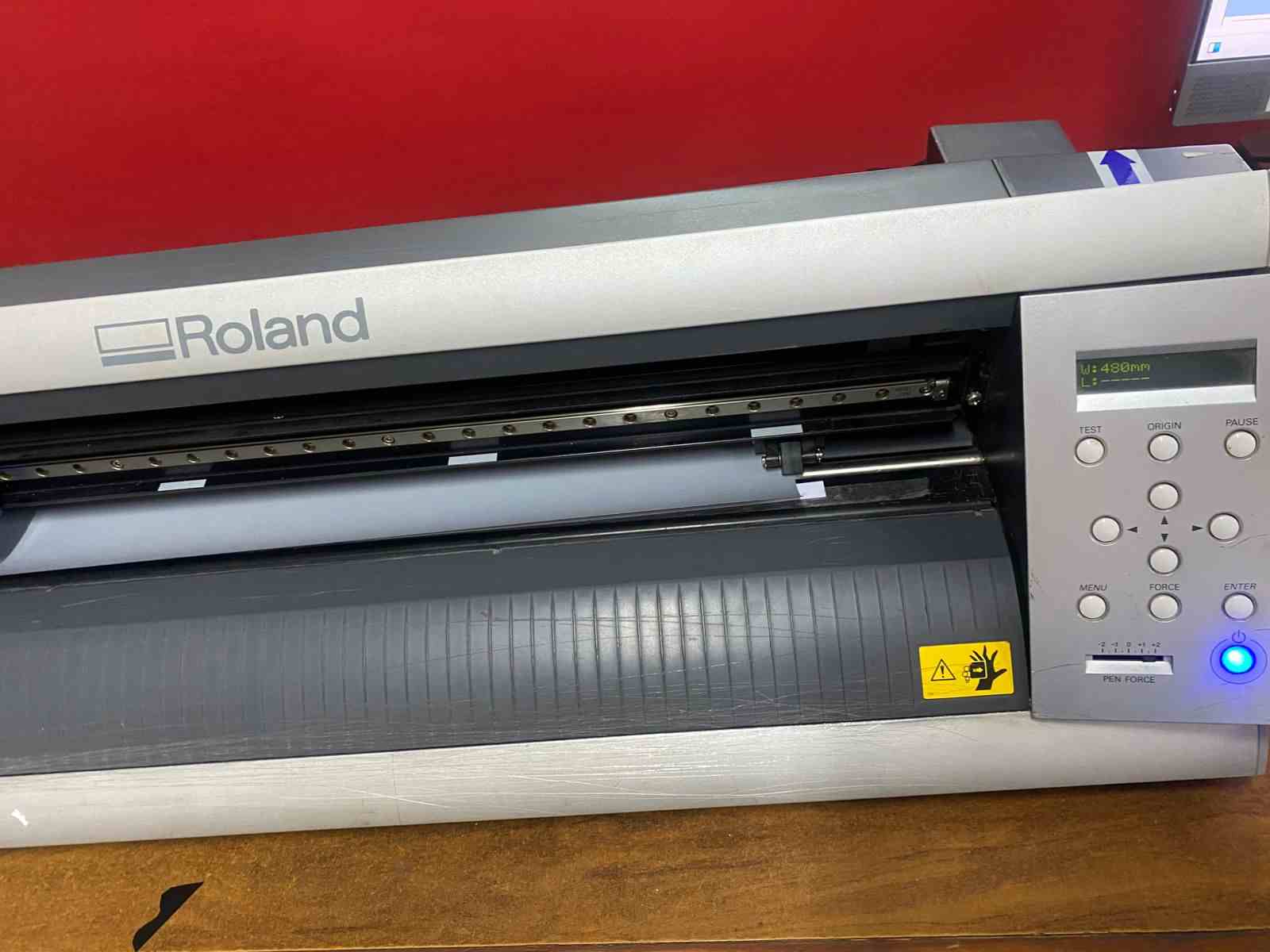
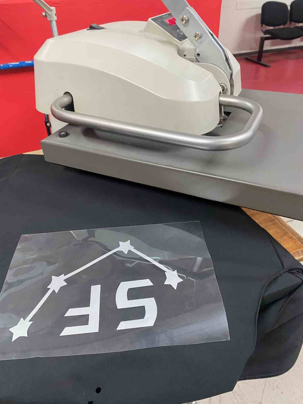
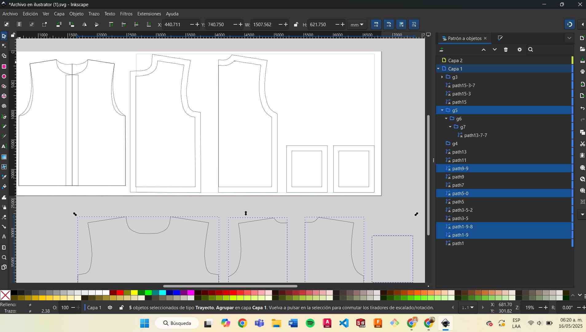
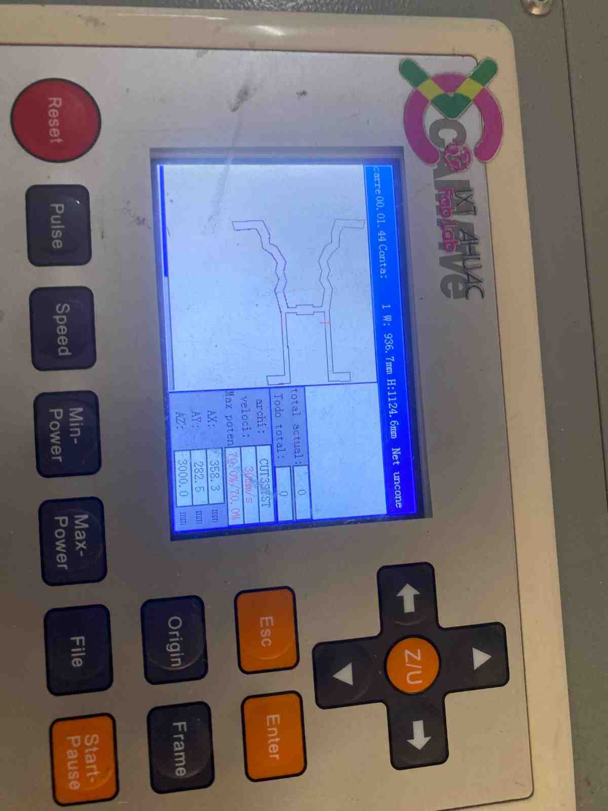
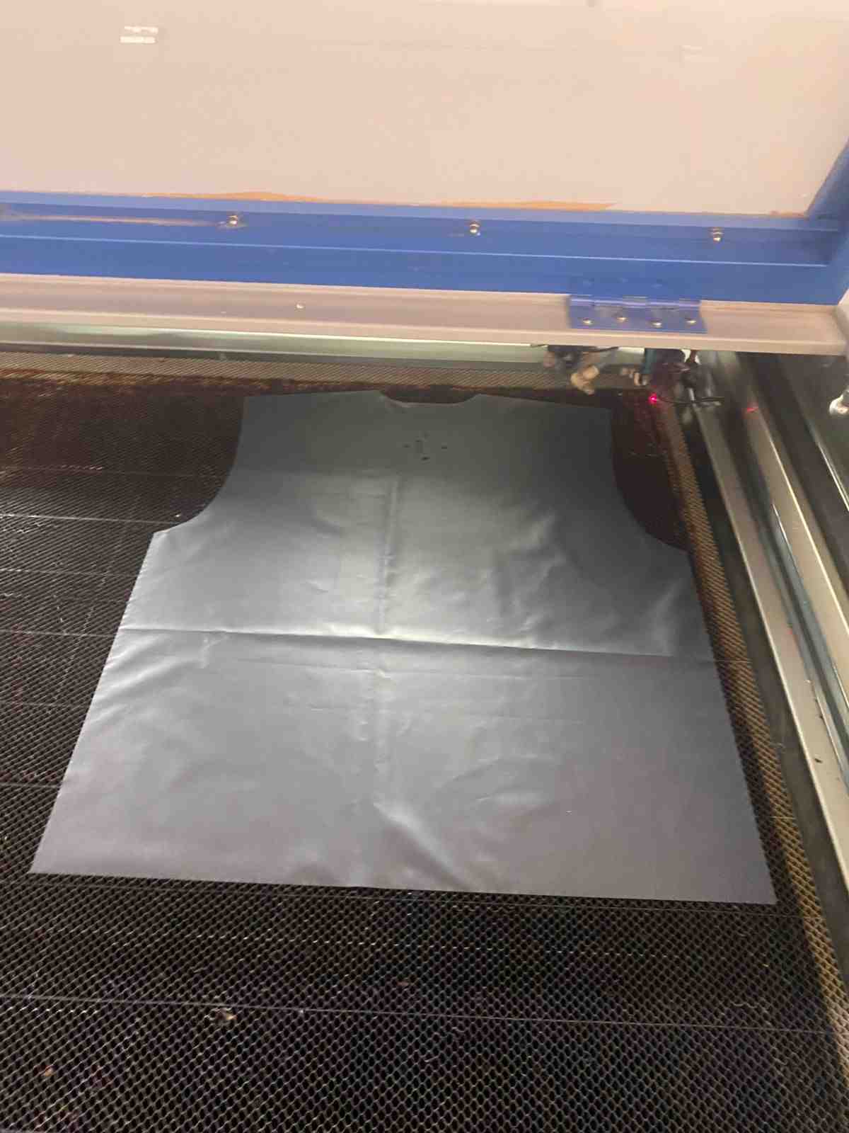
Laser Cutting
The pattern design for the vest can be seen in week 2
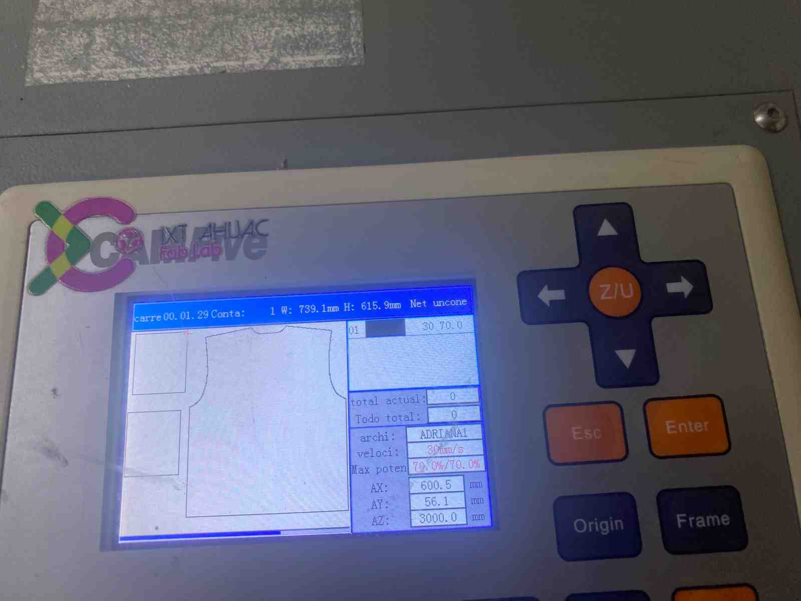
I cut the fabric in parts using 100% polyester. The laser settings I used were:
- Power: 70%
- Speed: 30%
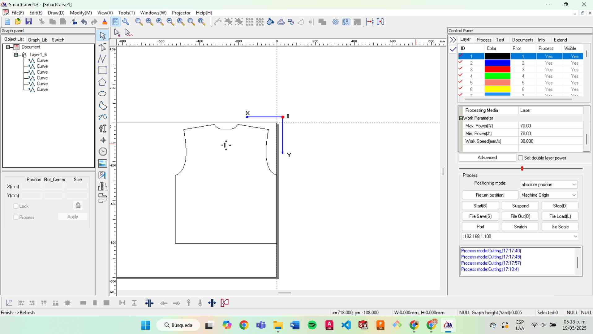
Usign the laser cutting
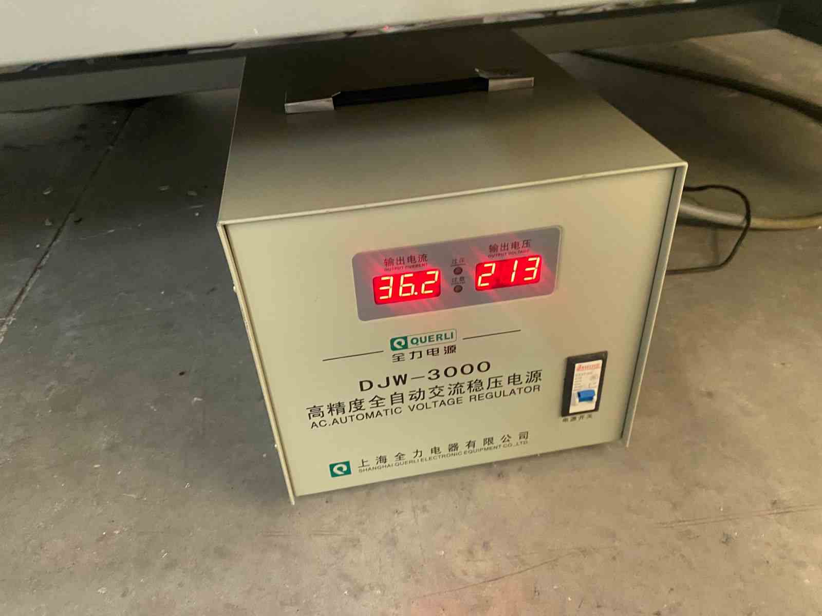
- I activated the power supply.
- I verified the air system was working.
- I turned on the laser machine.
- I deactivated the emergency stop button.
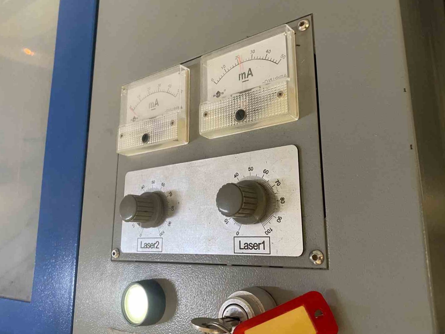
- I inserted the key and turned it to power the laser.
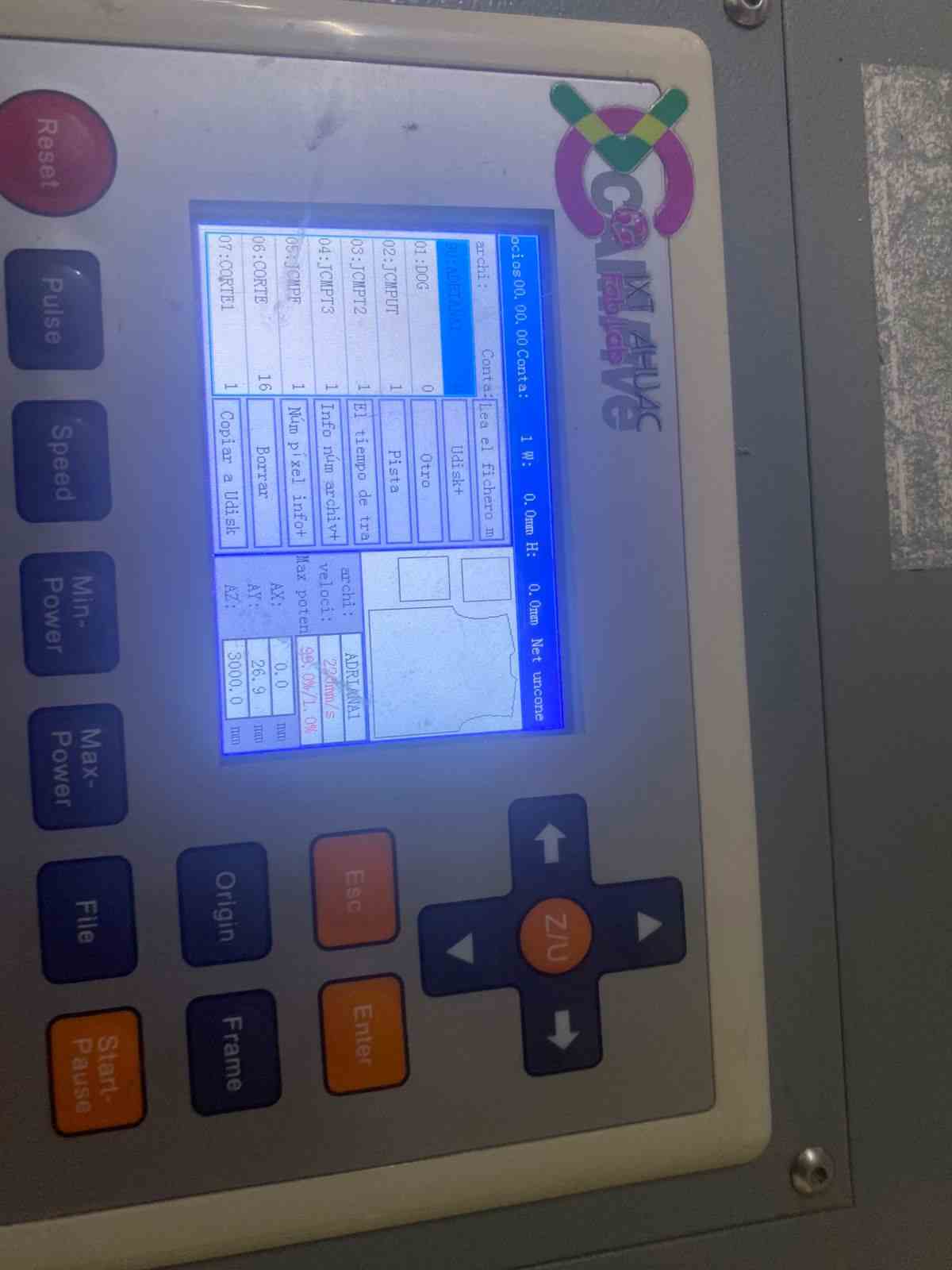
- I connected the USB drive to the machine.
- I chose my file from the USB.
- I pressed "Frame" to check the cutting area.
- I turned on the laser.
- I pressed "Start" to begin the cutting process.
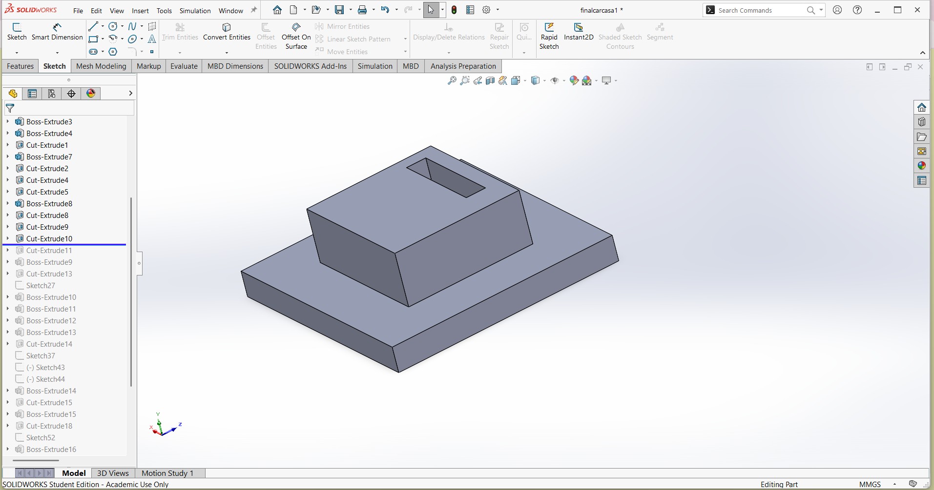
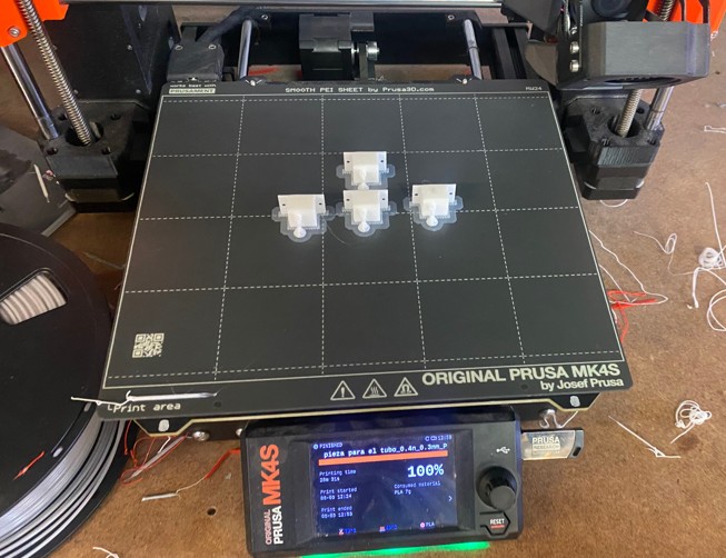
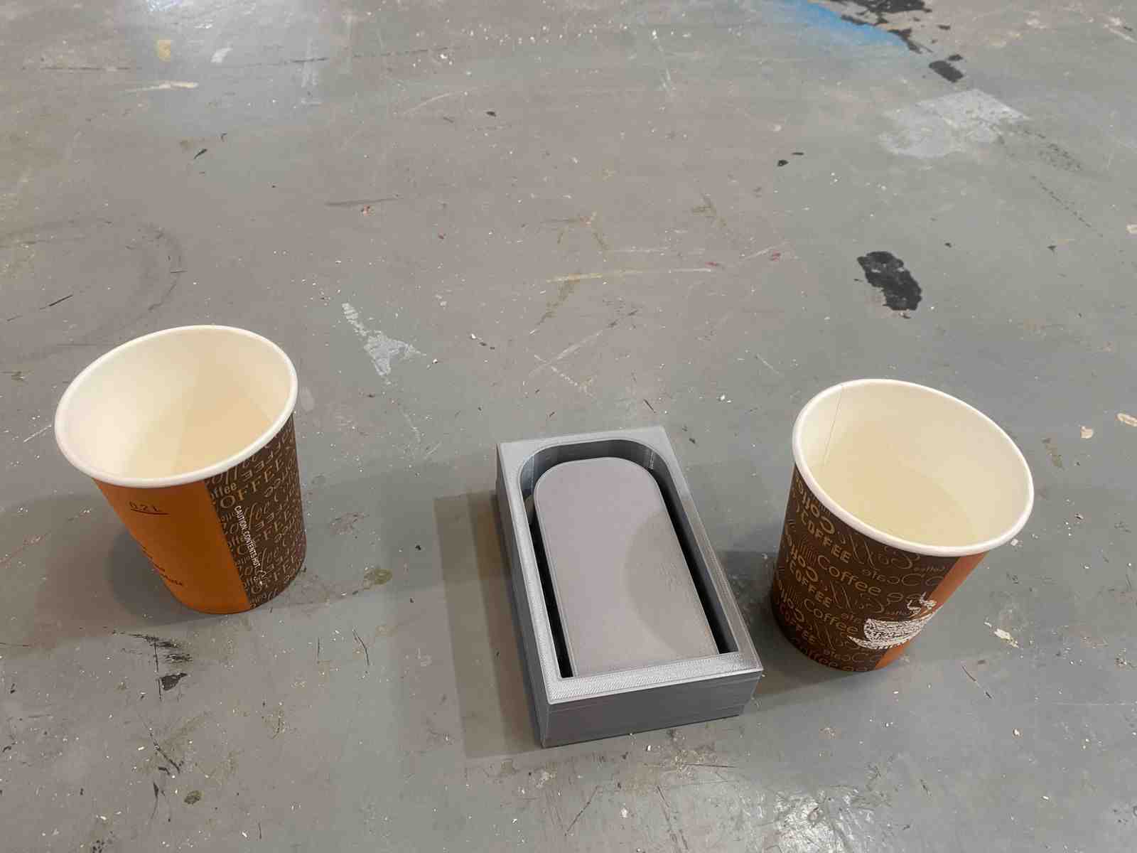
Molding and Casting
To make the vest comfortable at the pockets, I decided to use flexible silicone because it is soft.
You can see the detailed process in Molding and casting week
Conductive Thread and Sewing
I sewed each module by hand because the conductive thread was too thick for the sewing machine.
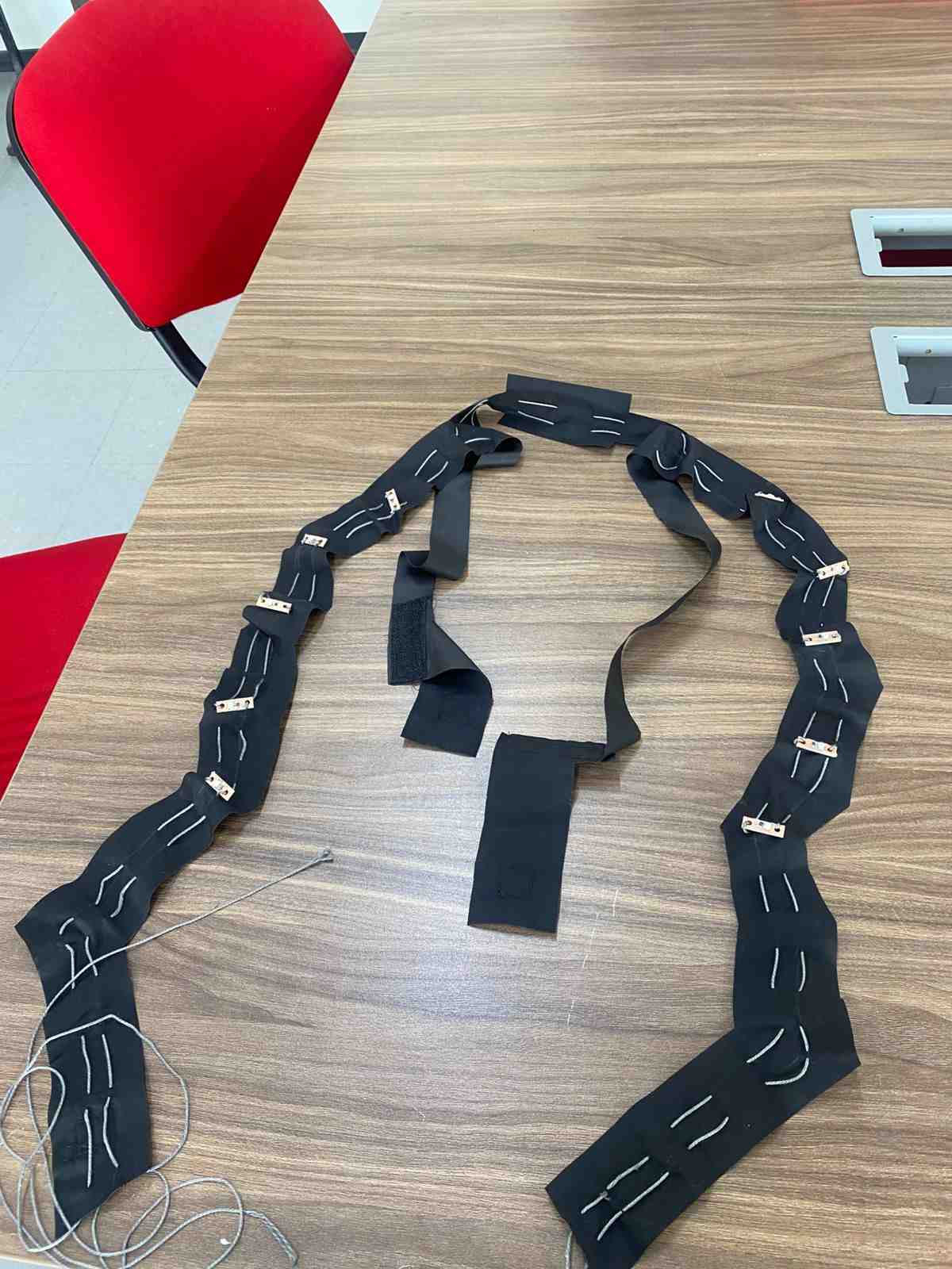
To make it washable, I added Velcro in some parts of the vest to attach and detach the LED modules.
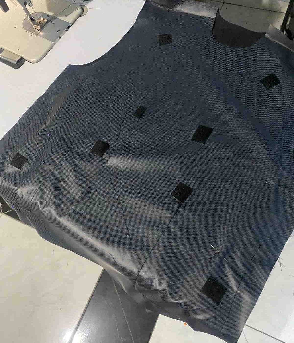
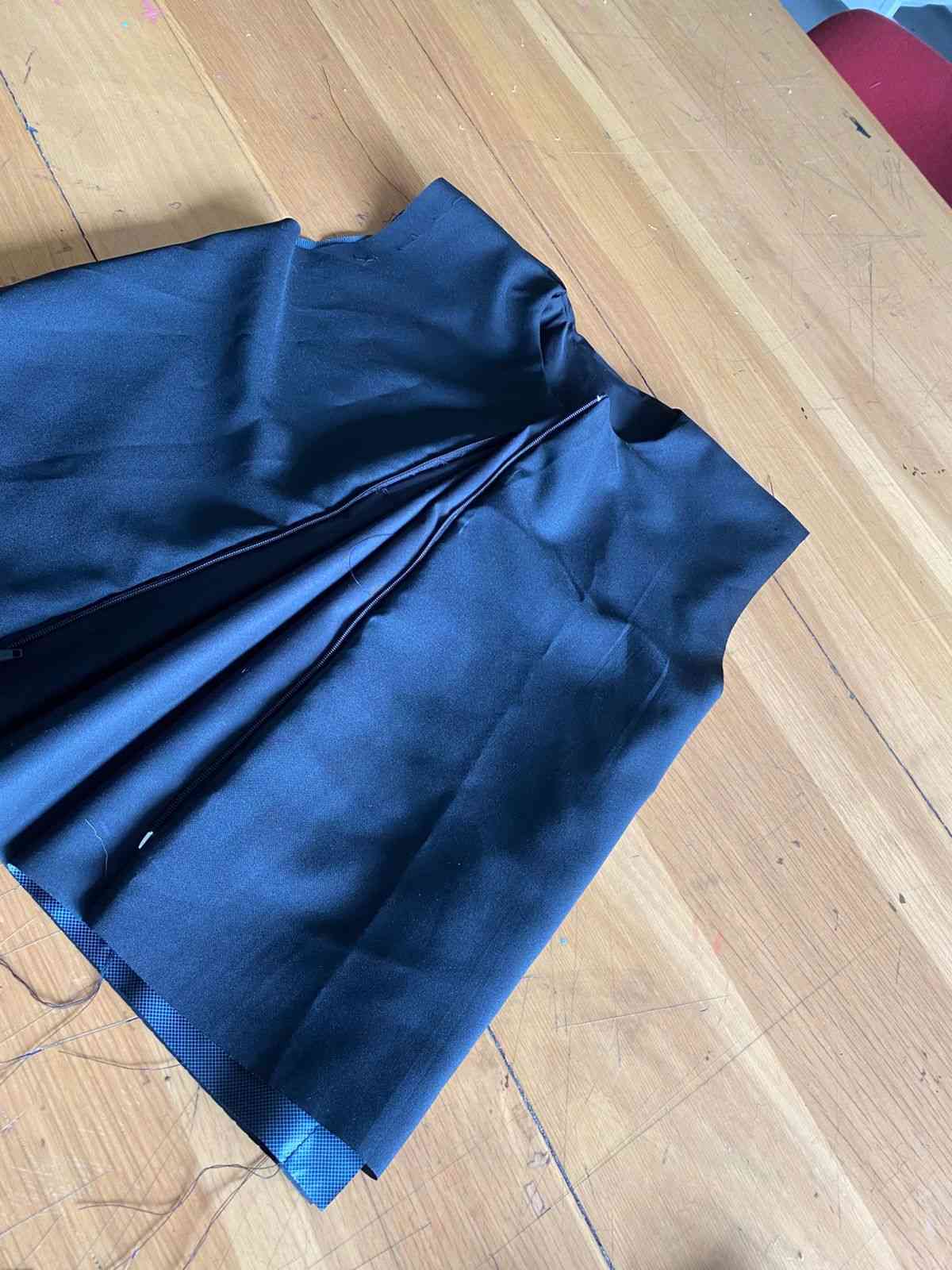
Sewing the Vest
- The shoulder seams of both the outer fabric and lining were sewn separately.
- The zipper was inserted between the outer fabric and lining (right sides facing) and sewn on both sides.
- The neckline, front edges, and lower front hem were sewn, joining the outer fabric and lining (right sides together).
- Two internal pockets were added with hidden openings to discreetly route electronic components.
- Velcro was sewn inside the vest, allowing for a removable fabric panel with conductive thread.
- The armholes were sewn, joining the outer and lining fabric (right sides together).
- The side seams were sewn, connecting outer and lining layers.
- The vest was turned right-side out.
- The final opening was closed using an invisible stitch.
Final result: A fully lined vest with no visible seams, a neatly finished zipper, and two hidden internal pockets for integrating electronics.