2. Computer-aided design
In week two, I explored different programs.
2D Design
In 2D design, I used two programs: Illustrator and Inkscape.
Illustrator
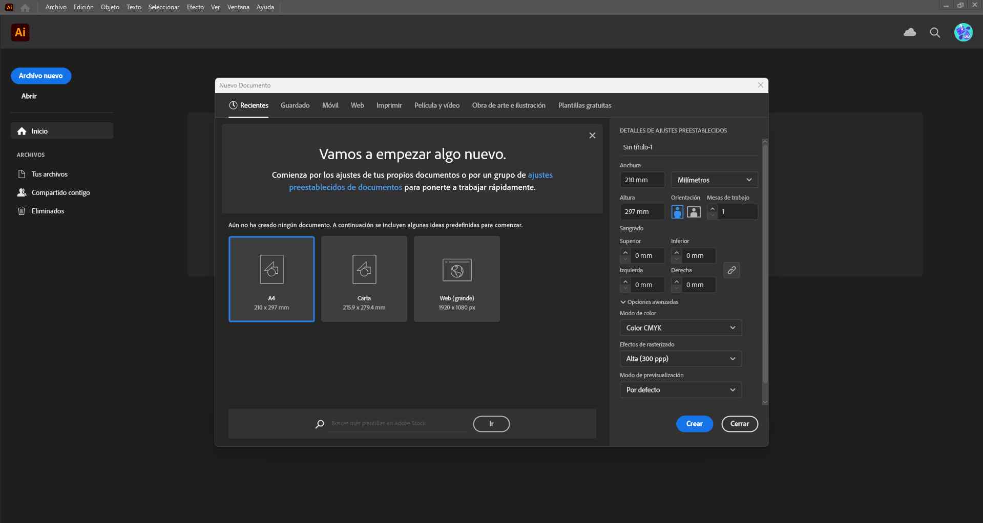
In this program, I decided to create a pattern for a vest for my final project. First, I have to choose a type of document.
Then, I had to start by creating a rectangle, and within it, I built the structure of the pattern using the “Line Tool”.

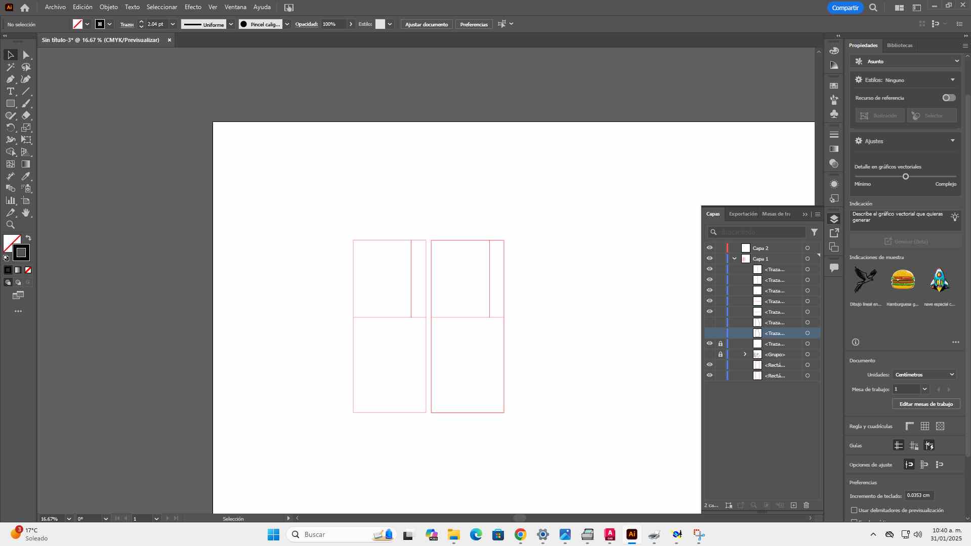
I used the 'Pen Tool' to shape the vest pattern, adjusting it according to my measurements.
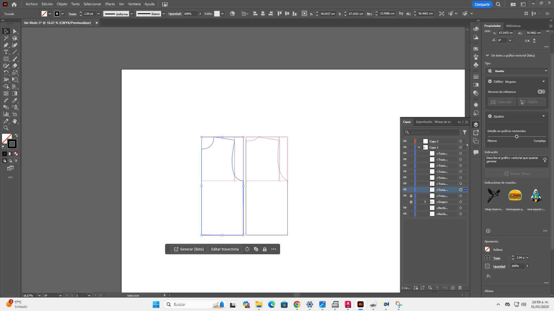
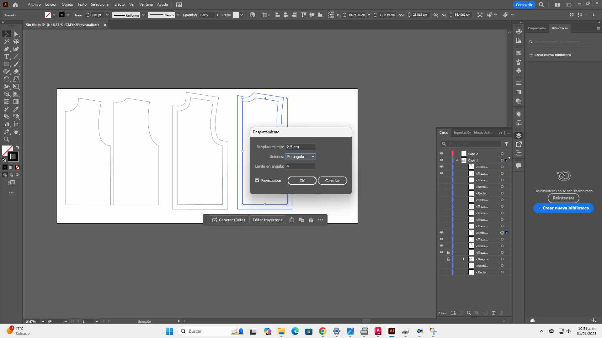
To add the contour, I had to learn a new tool called 'Offset.' The contour measured 2.5 mm, and I added this measurement for sewing.
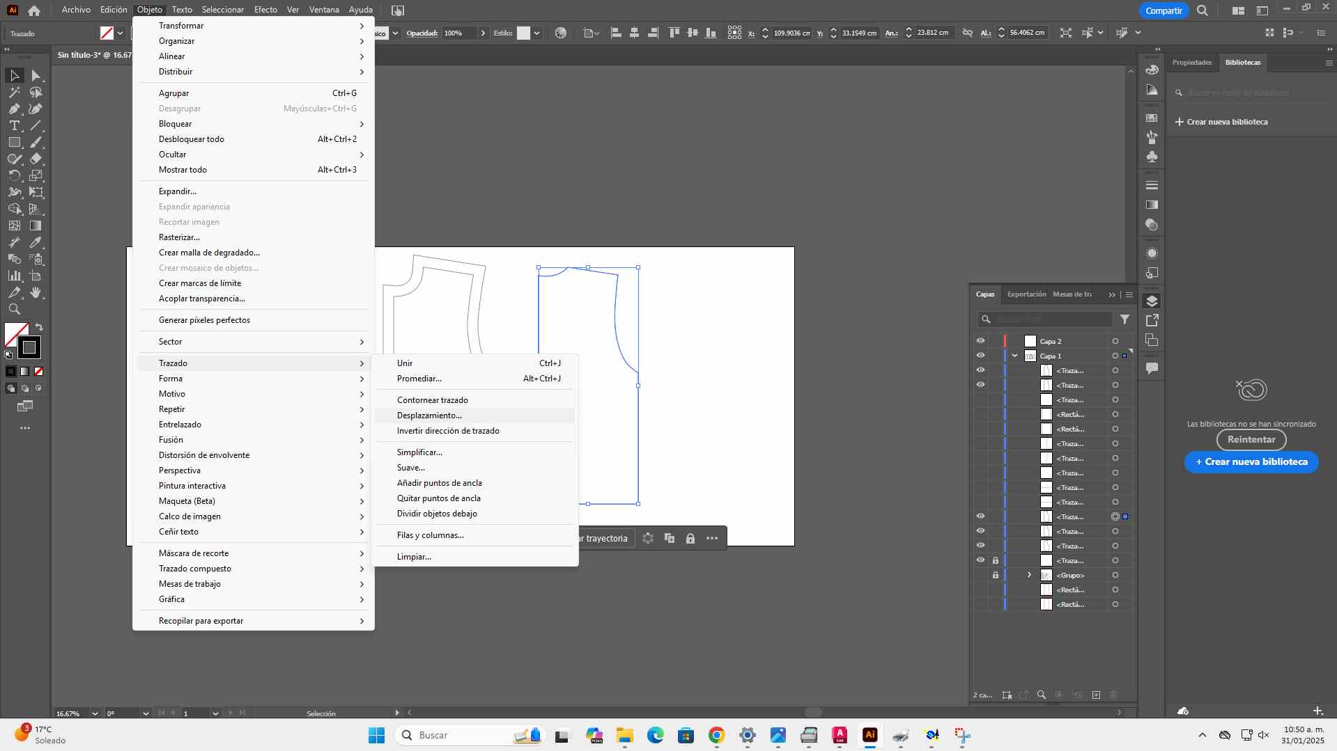
To finish I decided to add rectangles for the bags where the components will go.
.jpg)
Inkscape
I had never used this program before, and I found it very interesting.
In Inkscape, I decided to create my logo for my final project.
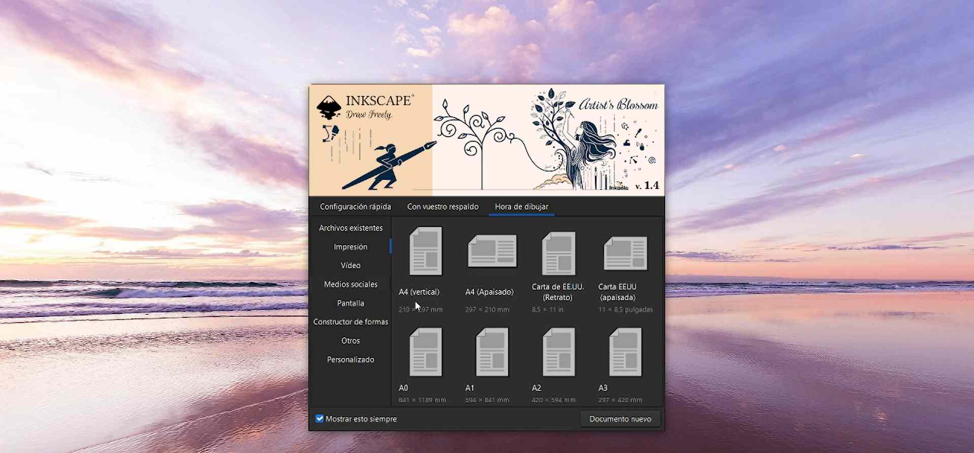
First, I had to choose the paper size.
Then, I started placing stars and a line behind them.
.jpg)
.jpg)
Finally, I added text to the figure.
.jpg)
.jpg)
Files
In my opinion, I prefer illustrator even though it is paid because it has more advanced features to work with ease in large jobs. Although I would use inskape for simple drawings like logos because I like the ease of modifying nodes and making quick designs.
3D SOFTWARE
In this practice, I tried two different programs: SolidWorks and Fusion 360.
SolidWorks
SolidWorks is a 3D design software that allows you to create digital models of parts and assemblies.
When we start in SolidWorks, we will see these options from which we can choose depending on our needs.
.jpg)
In this case, I will choose the "Part" option to create a case for my sensor.
Upon entering, we will encounter the main screen and a menu known as the design tree. This allows us to navigate between the different parts of our model, modify or delete operations, and organize the design more easily.
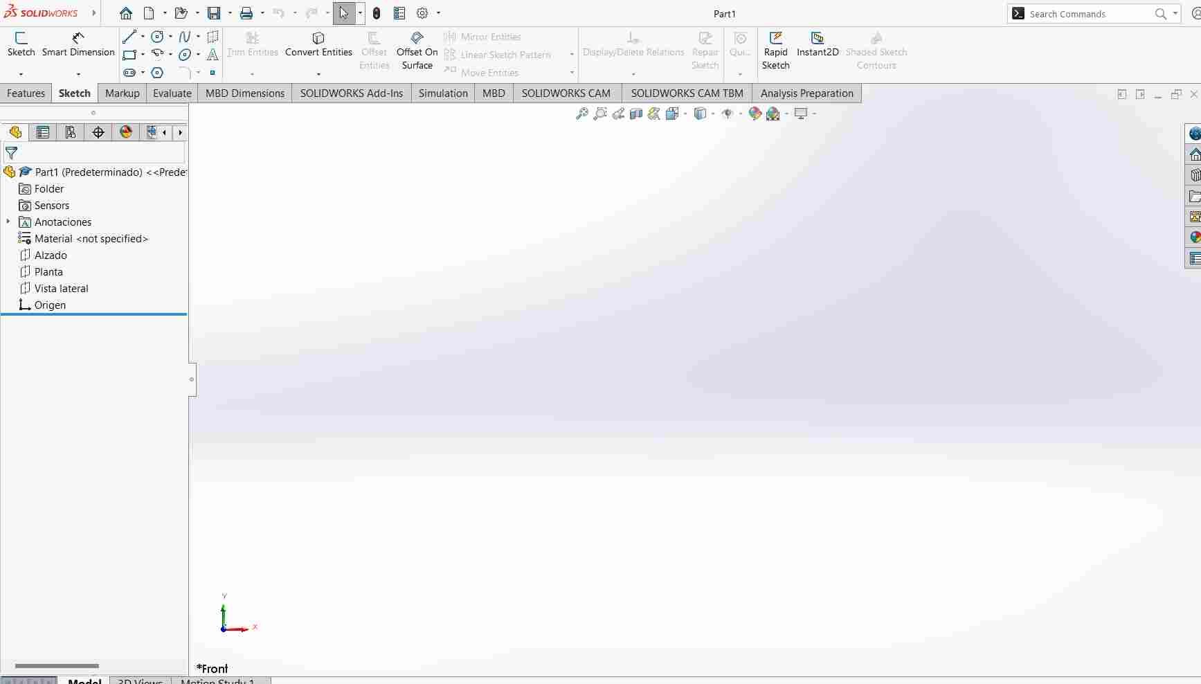
Inside the tree, we find the following views:
- Front View: Shows the model from the front.
- Top View: Shows the model from above.
- Side View: Shows the model from the left or right side.
Before starting to make our model, we need to understand some of the basic tools.
Some basic tools are:
Sketching Tools
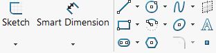
- Line: Defines edges and reference axes.
- Circle: Used for holes, shafts, or revolved bases.
- Rectangle: Great for structures with right angles.
- Arc: Smooths transitions between straight edges.
- Polygon: Perfect for nuts, gears, or geometric cuts.
- Smart Dimension: It is used to set measurements.
Feature Tools
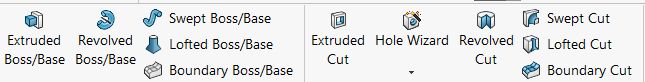
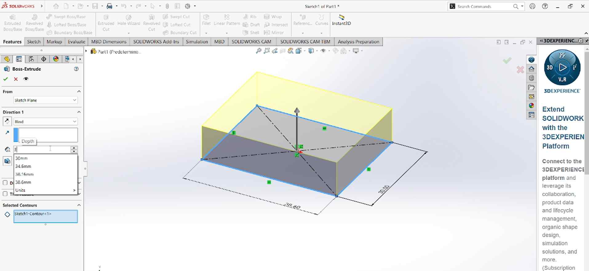
- Extrude (Extrude Boss/Base): Turns a 2D sketch into a solid. You need to draw a 2D sketch, click Extrude Boss/Base, set the thickness, and apply.
- Extruded Cut (Extruded Cut): Cuts material using a sketch. You need to select the face to cut, create a 2D sketch where you want to cut, then choose Extruded Cut, set the depth, and apply.
Editing Tools
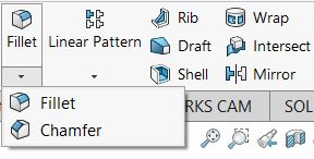
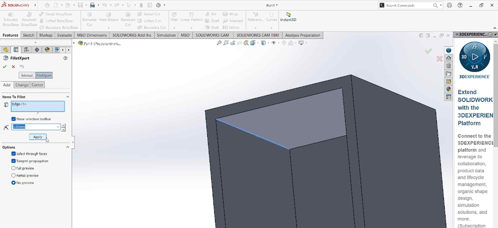
- Fillet: Softens sharp edges and corners. You need to select an edge, click Fillet, adjust the radius, and apply.
- Chamfer: Cuts an edge at an angle for a sleek look. You need to pick an edge, click Chamfer, set the distance/angle, and confirm.
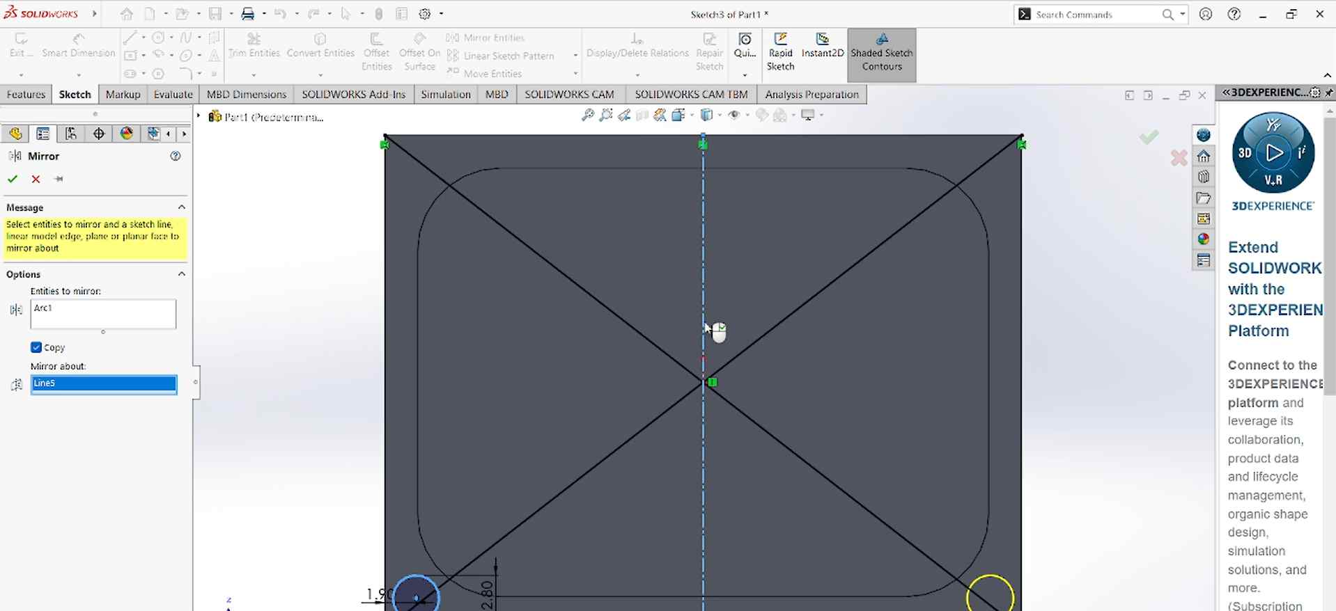
- Mirror: Flips a part or sketch to keep things symmetrical. You need to select the feature, click Mirror, choose a reference plane, and confirm.
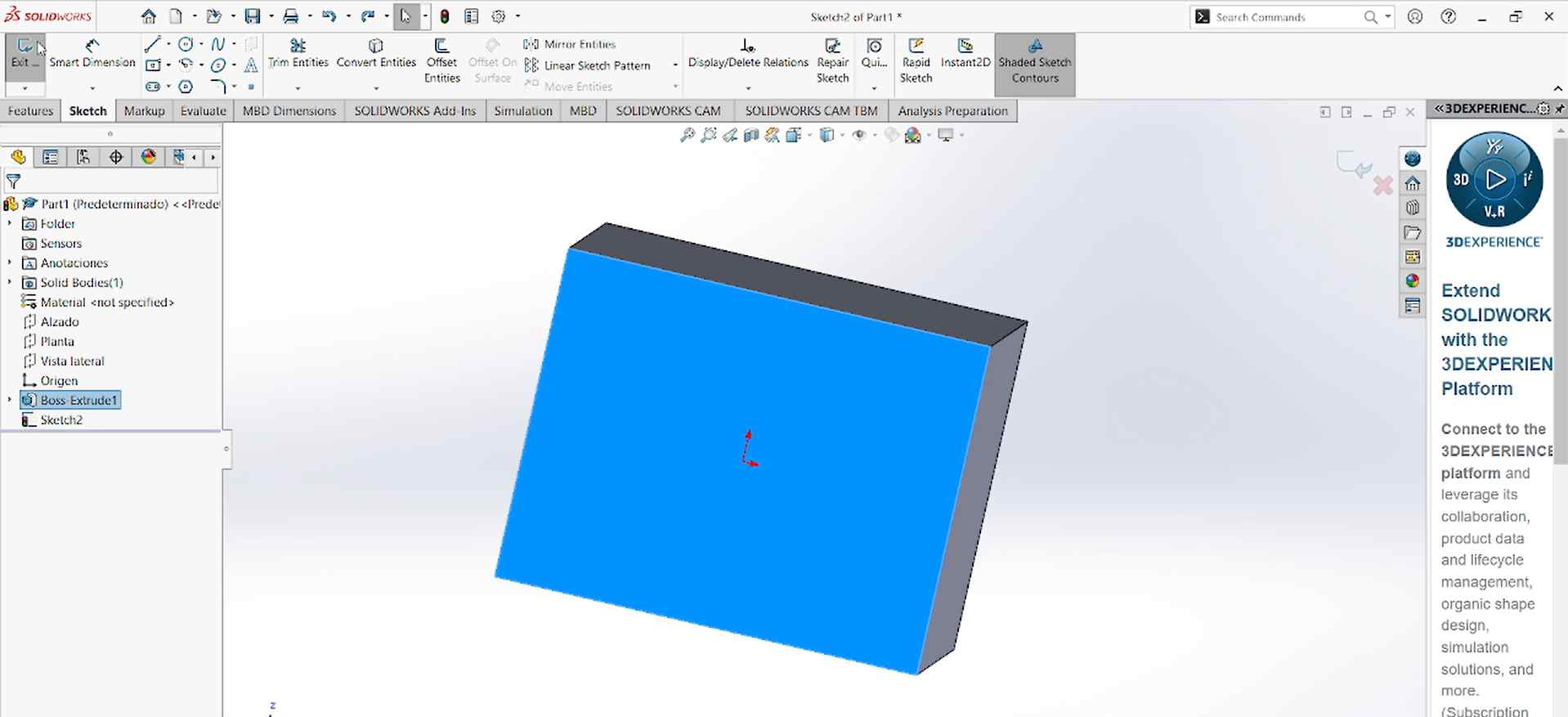
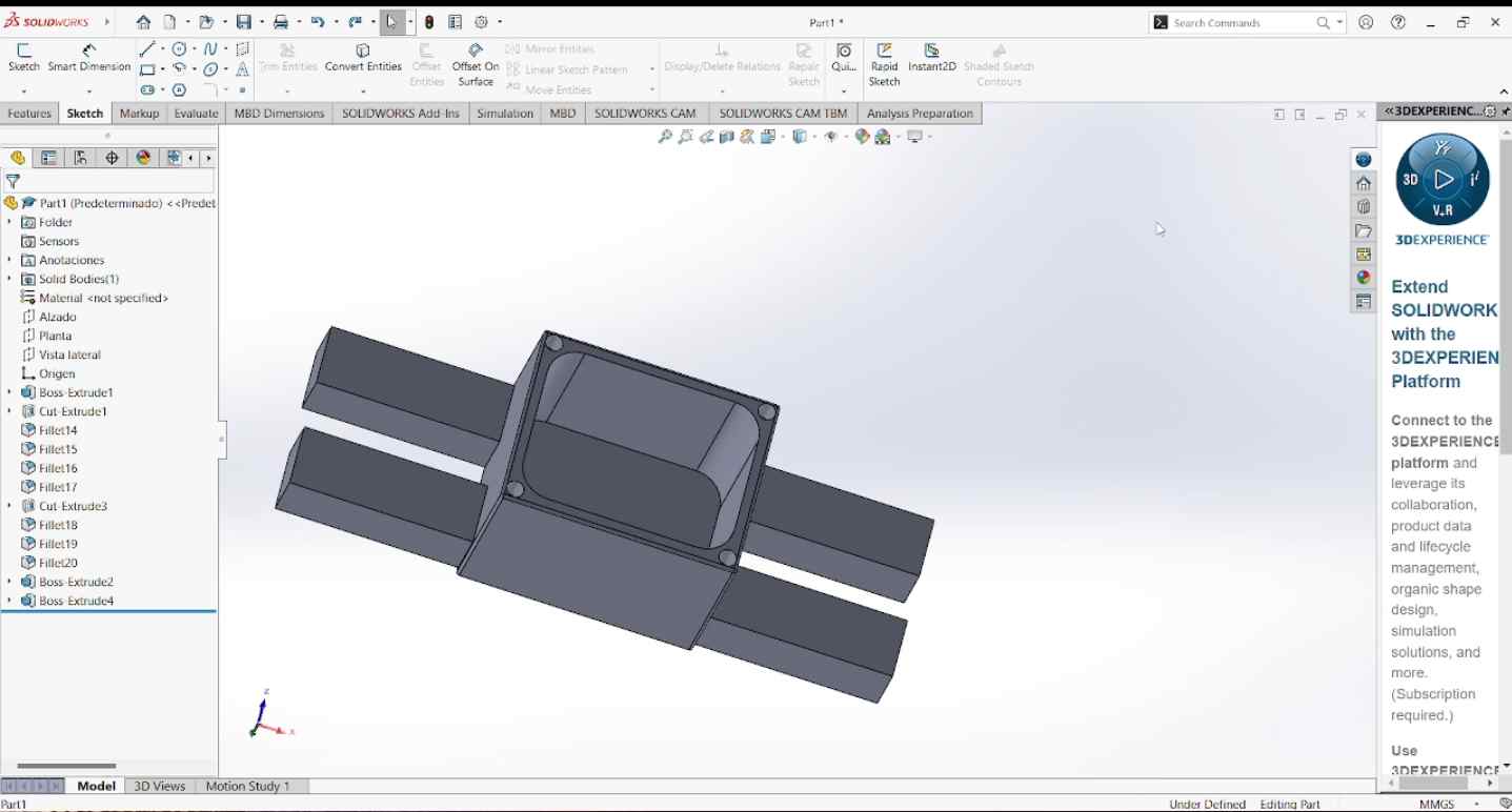
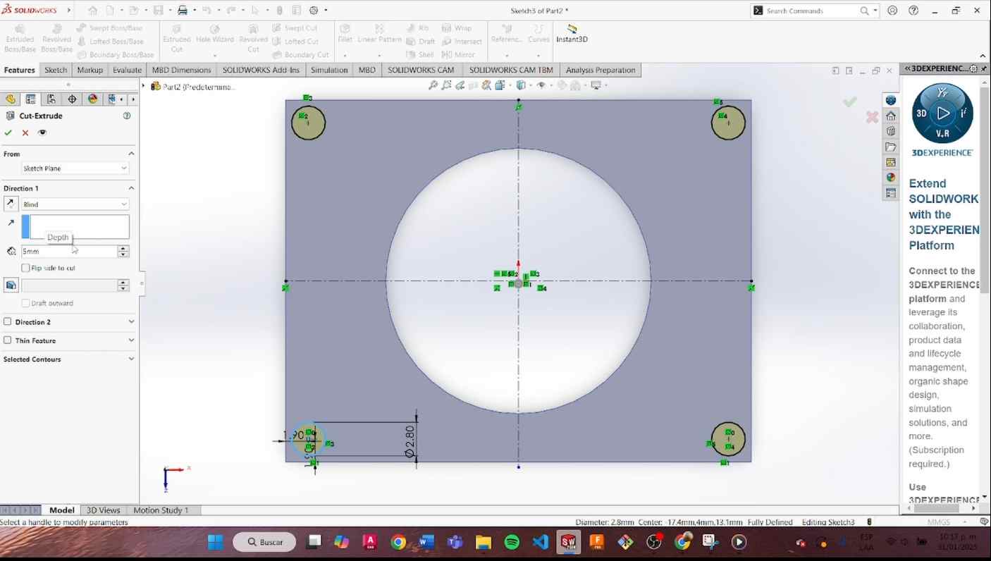
These are the steps I followed to make my possible case:
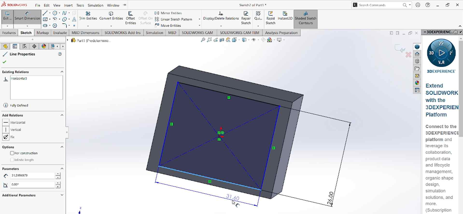
- I created a rectangle with dimensions of 38.6 mm * 30 mm and a width of 30.5 mm, with an extrusion of 26.5 mm.
- I added a "fillet" of 5 mm on the corners.
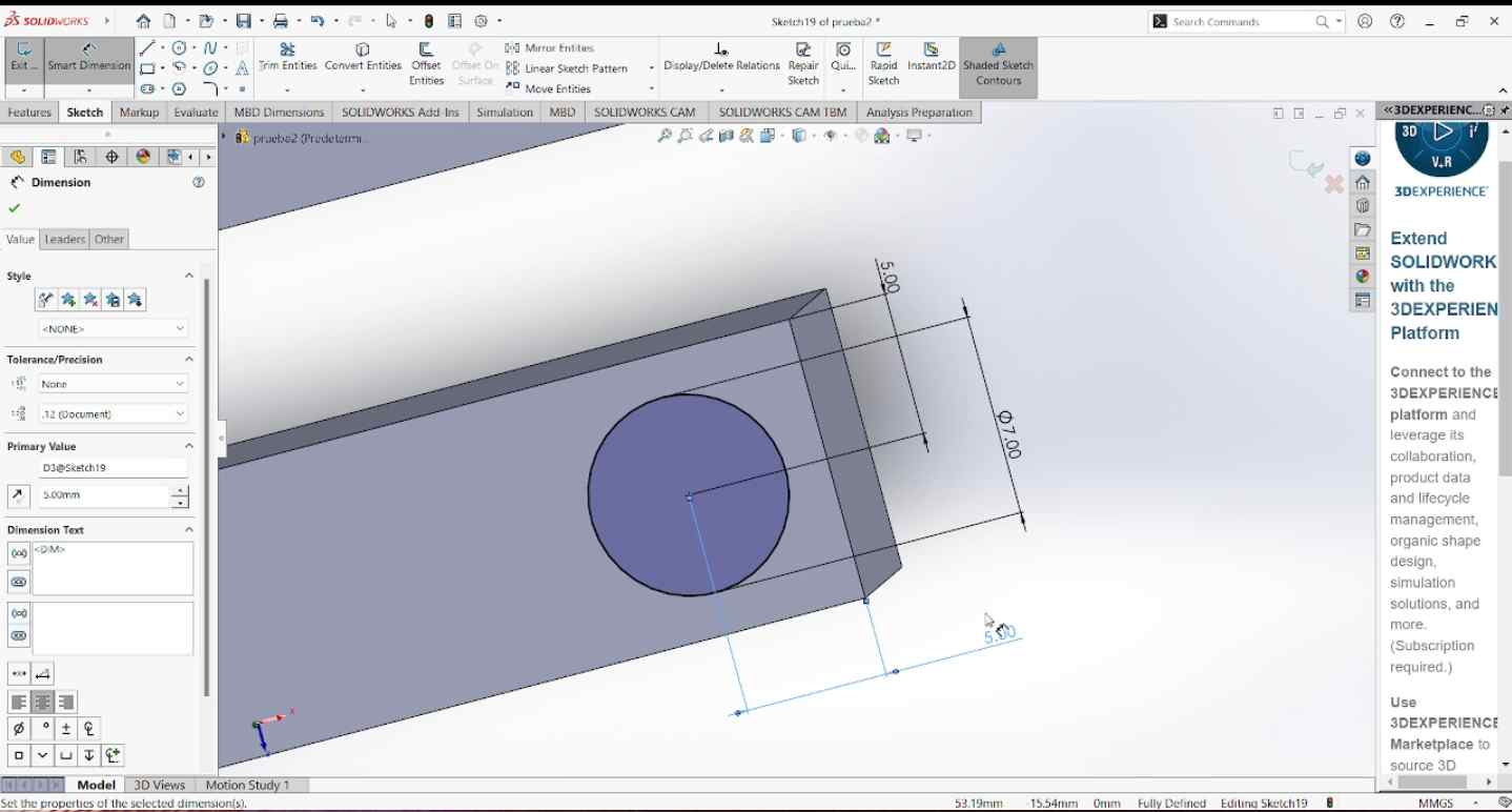
- I made four circles for the screws, each with a 2.80 mm diameter and 5 mm depth. I used the "Mirror Entities" tool to copy the circles.
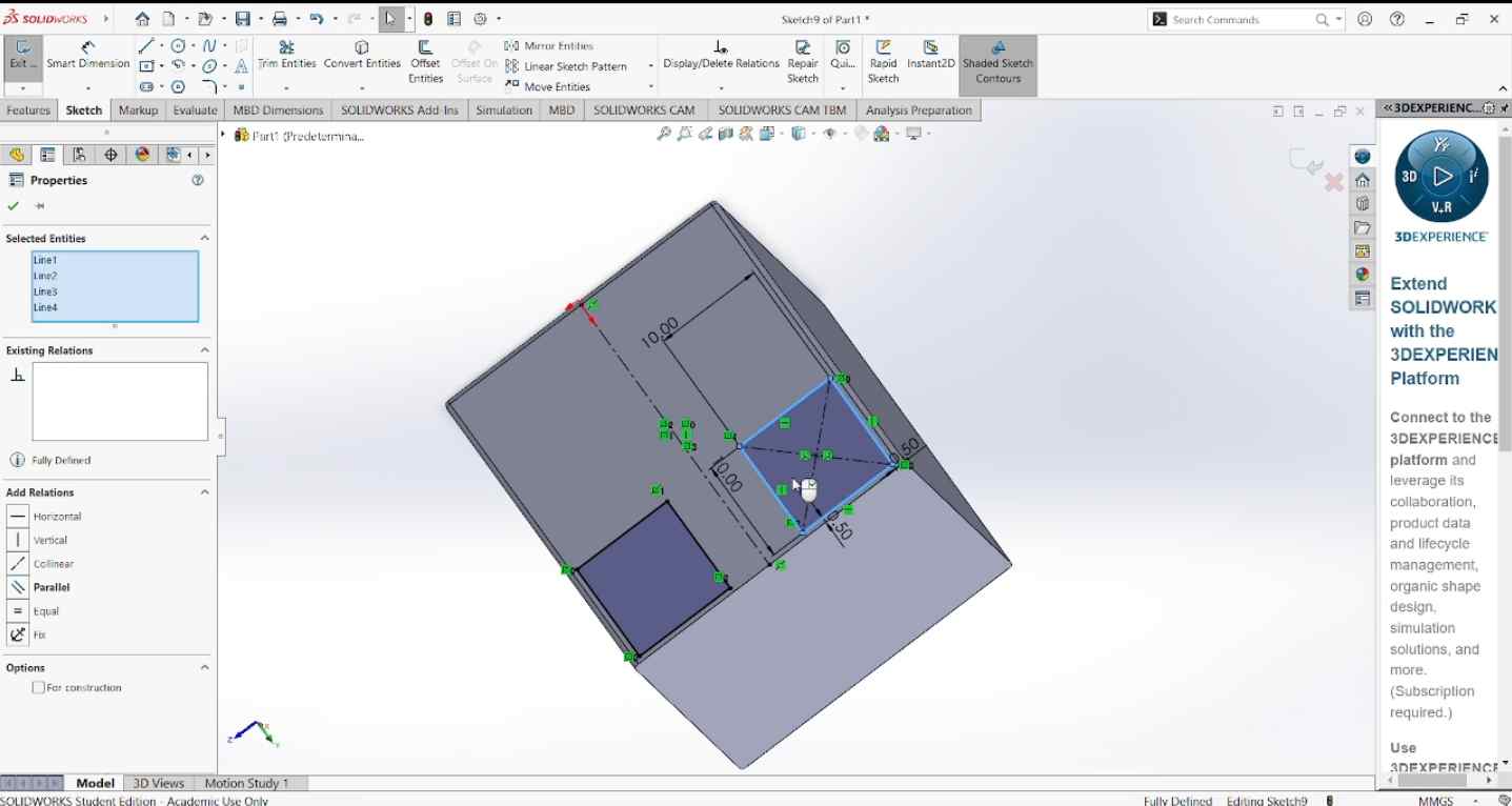
- Inside this part, I created two rectangles of 10 x 10 mm on each side, with a width of 30 mm. Inside these rectangles, I placed circles in the corners with a 7 mm diameter.
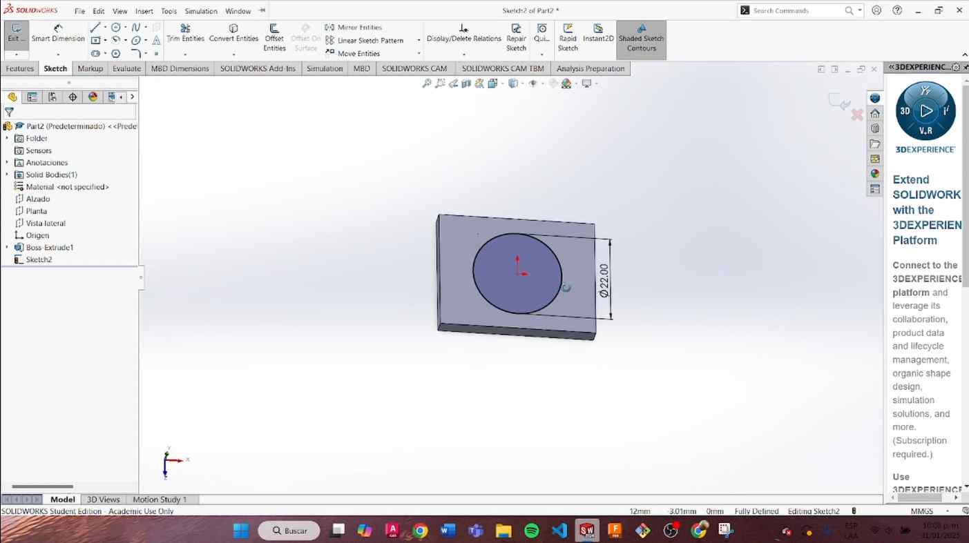
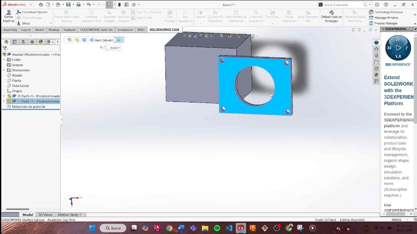
- I made another part for assembly, with dimensions of 38,6 mm x 30 mm, with a circle in the center of 22 mm diameter and placed four circles in the corners with a depth of 5 mm.
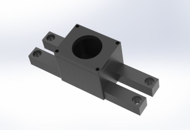
- Finally, I assembled the part and rendered it.
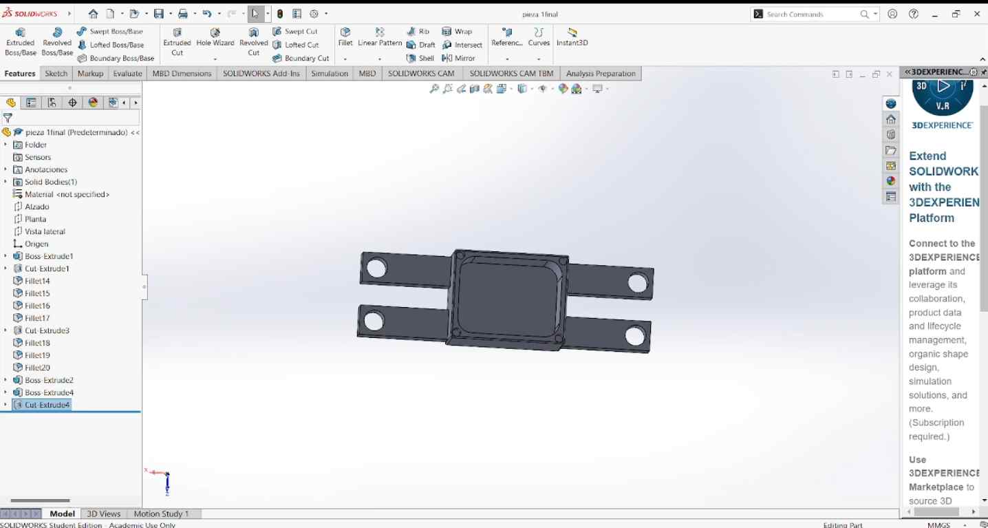
Here is a possible render of my case.
Here is a video of my process:
Fusion 360
Fusion 360 is a simple software that lets you create and edit 3D designs. It has tools for modeling, testing, and preparing designs for production.
When we enter Fusion 360, we will see the area where we will create our model.
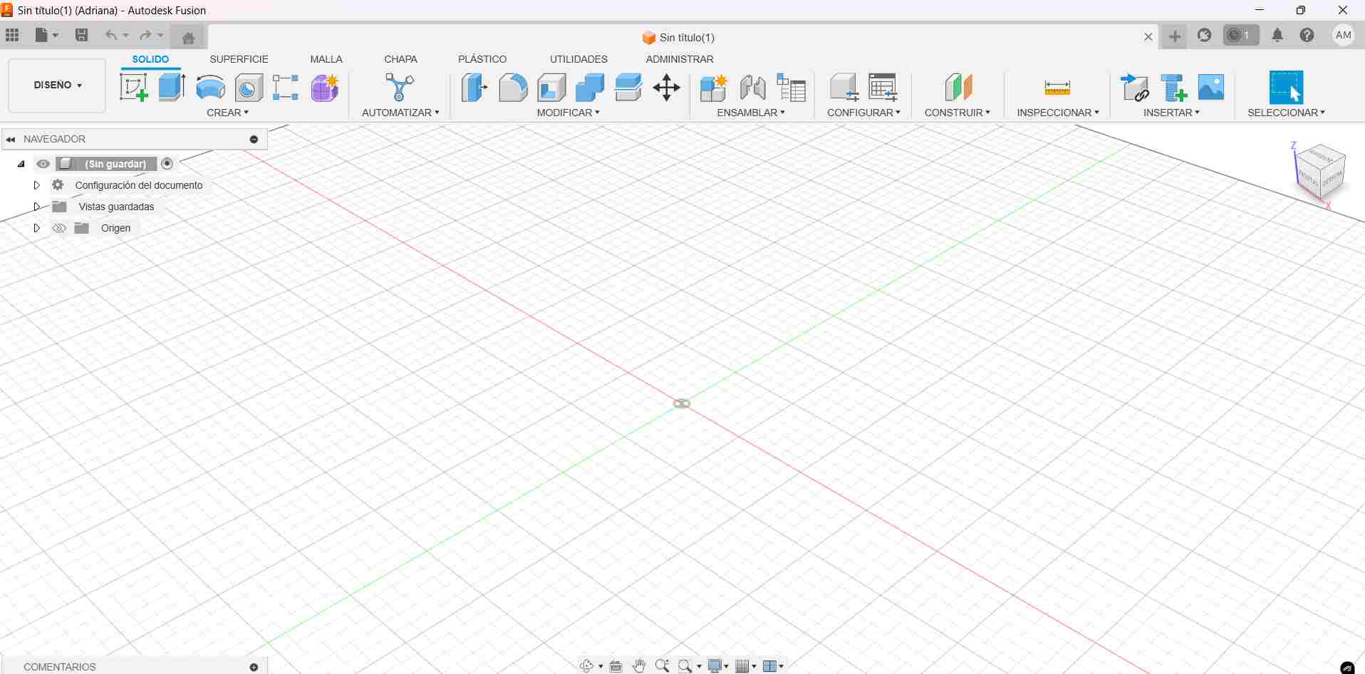
Some tools have similar names as in SolidWorks.
-compressed (1).jpg)
Here, we can find tools to modify, create a sketch, and feature tools.
The types of planes used in this program are:
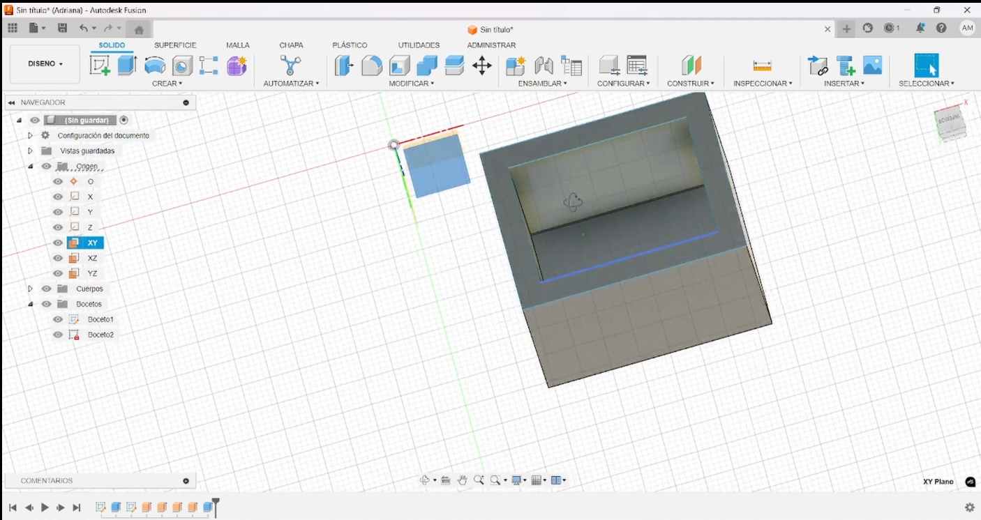
- XY Plane: It is the horizontal plane you work on when looking from above.
- XZ Plane: It is the vertical plane that lies along the X and Z directions.
- YZ Plane: It is the vertical plane that lies along the Y and Z directions.
In Fusion, I decided to make the same case I made for my sensor, but just a part of it.
Here’s the process:
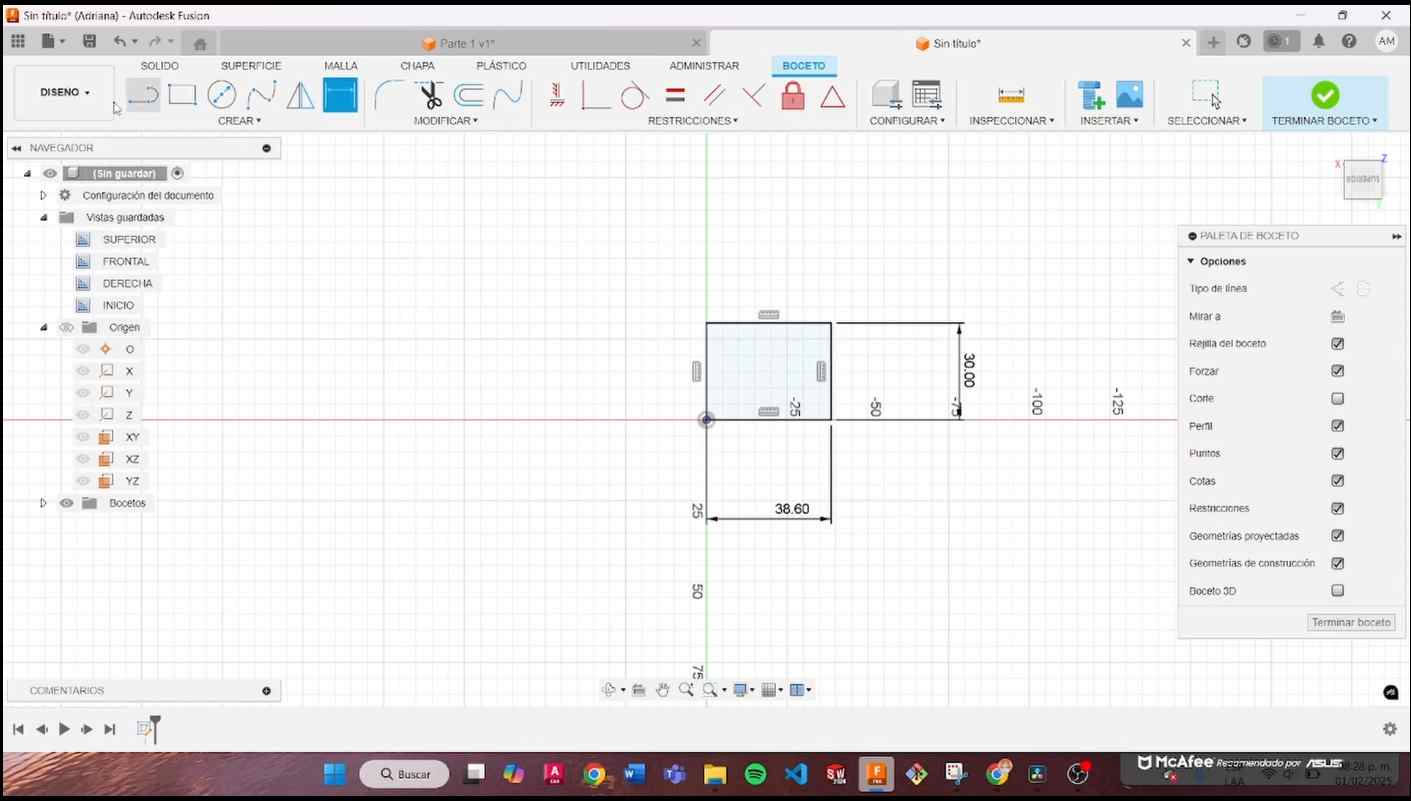
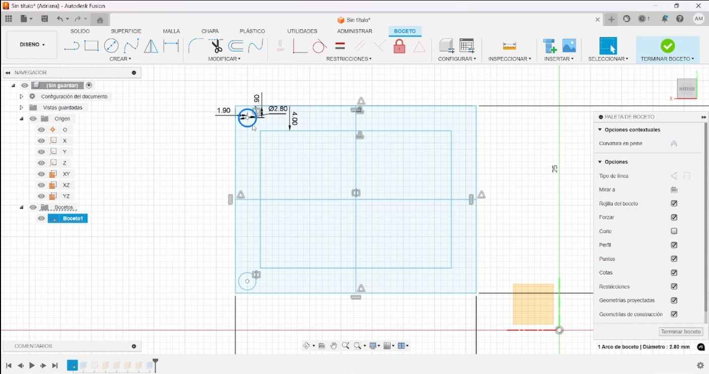
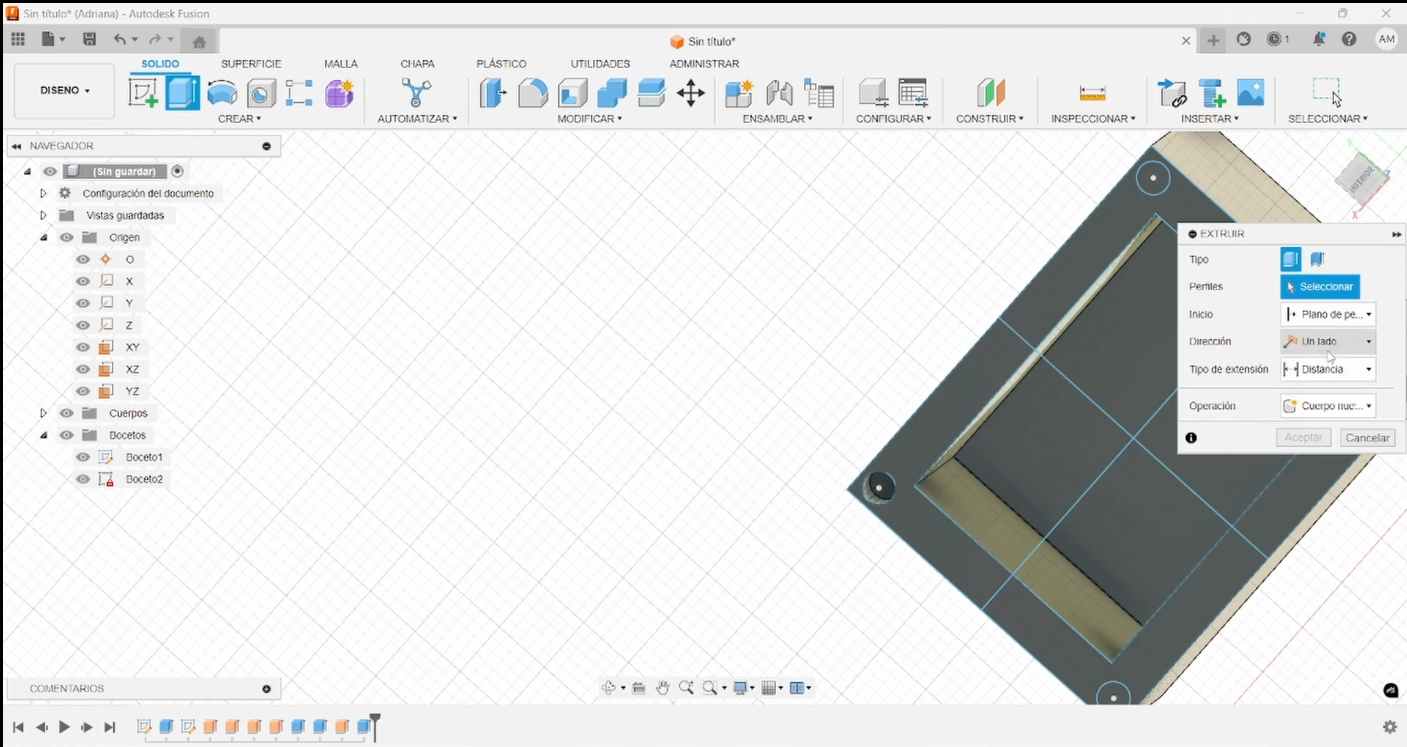
- I created a rectangle with the same dimensions as the previous one and added a width of 30.5 mm.
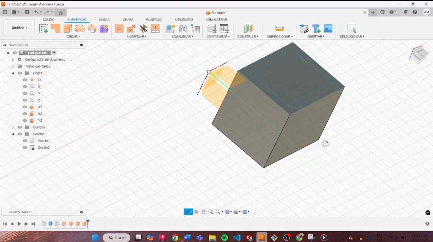
- I made an extrusion of 26.5 mm.
- I placed four circles in the corners with an extrusion of 5 mm.
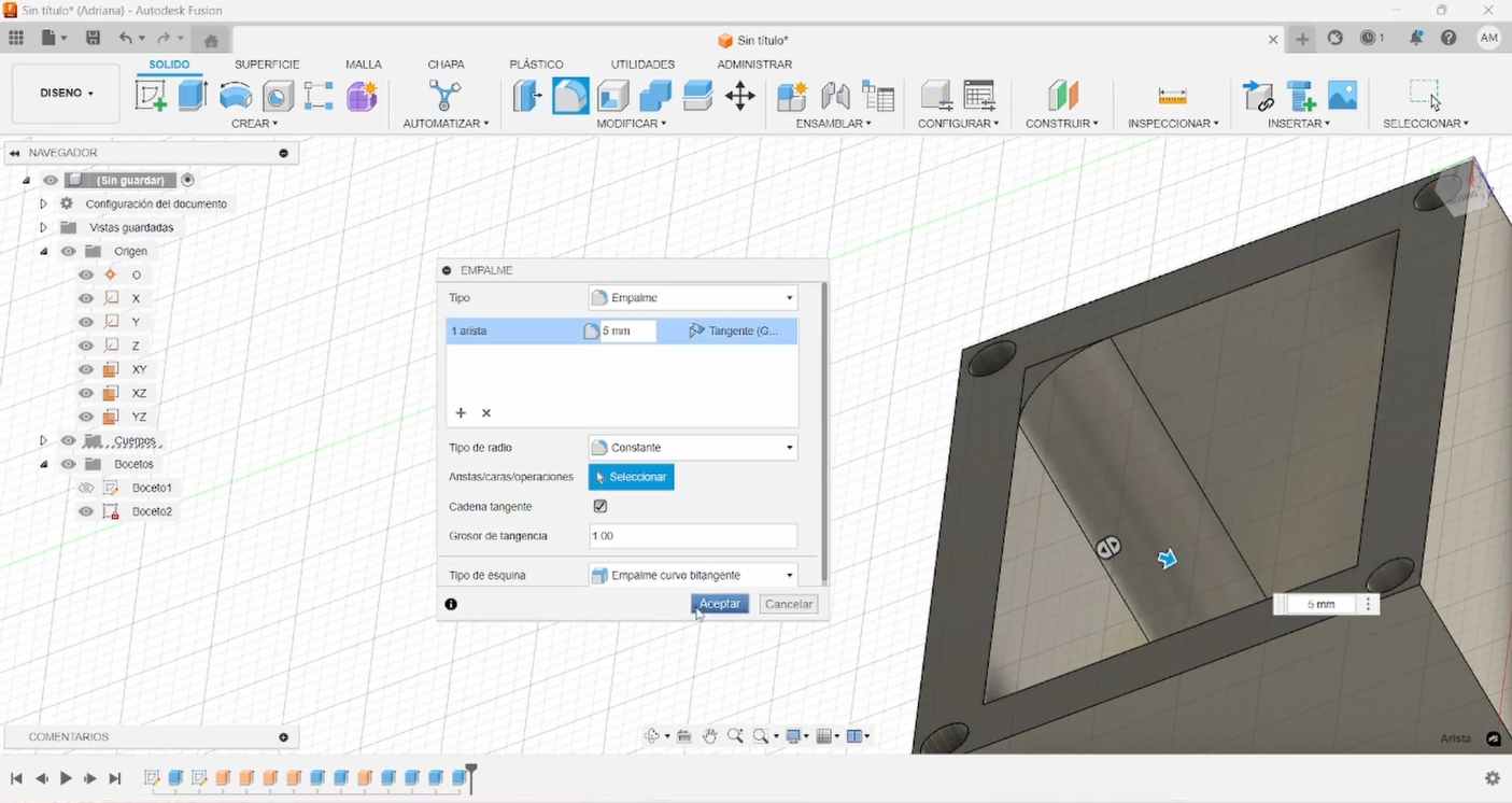
- I added a "fillet" of 5 mm to the interior corners.
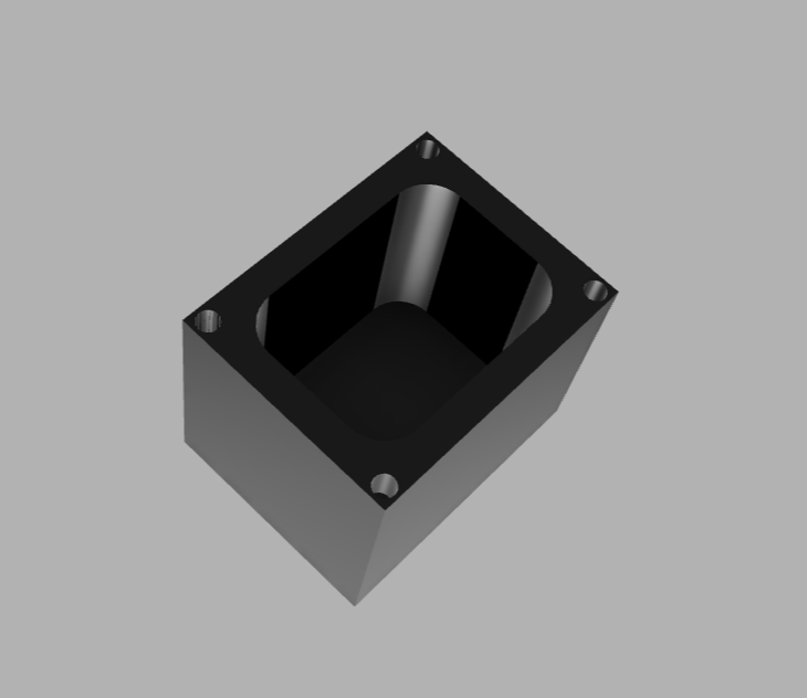
- Finally, I rendered the piece.
Here is a video of my process:
Between the two software programs, both are good. I preferred SolidWorks because I became more familiar with it and it has more tools and its layout is more visual and organized, with well categorized tools. However, I would use Fusion 360 for simpler jobs, as it can be more practical because the tools are very easy to apply.
Animation
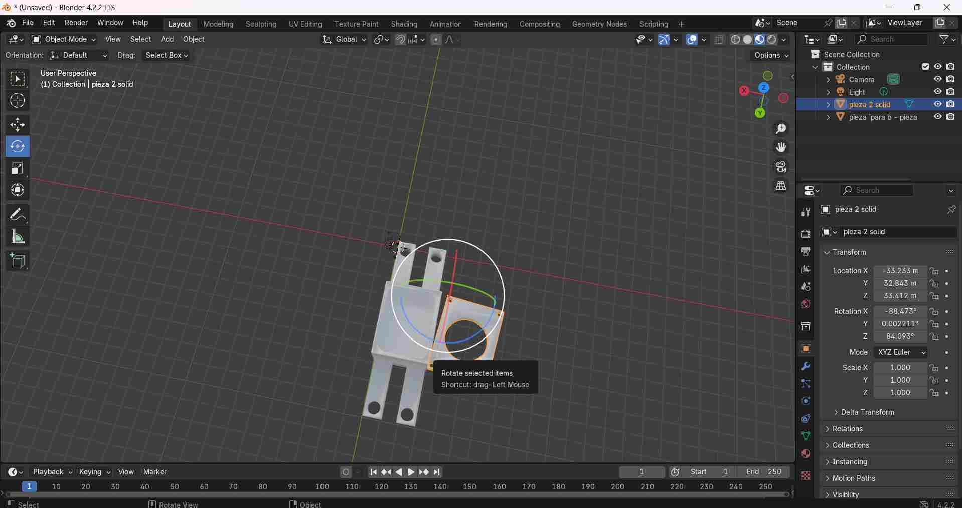
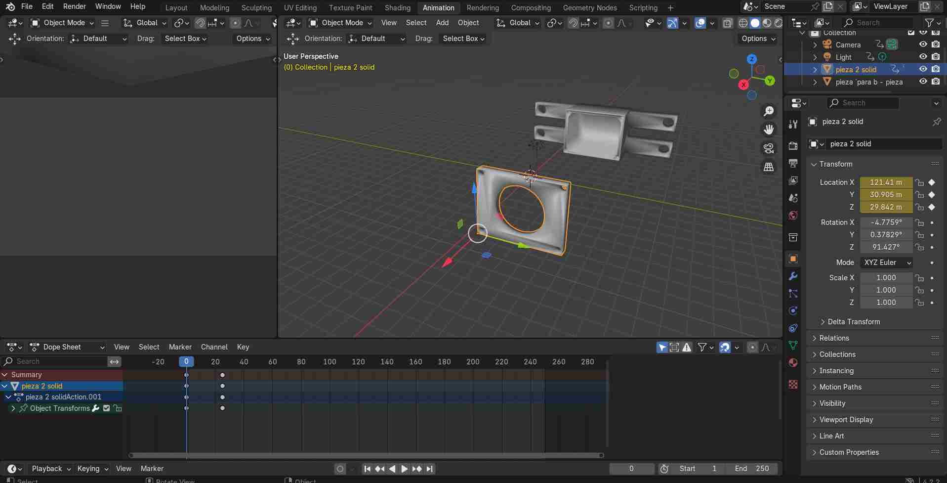
These are the steps I followed to make the animation of my case for my sensor:
- Save my file in STL in solidworks, to open it in Blender.
- Open my file and make the animation by placing dots that represented the movement.
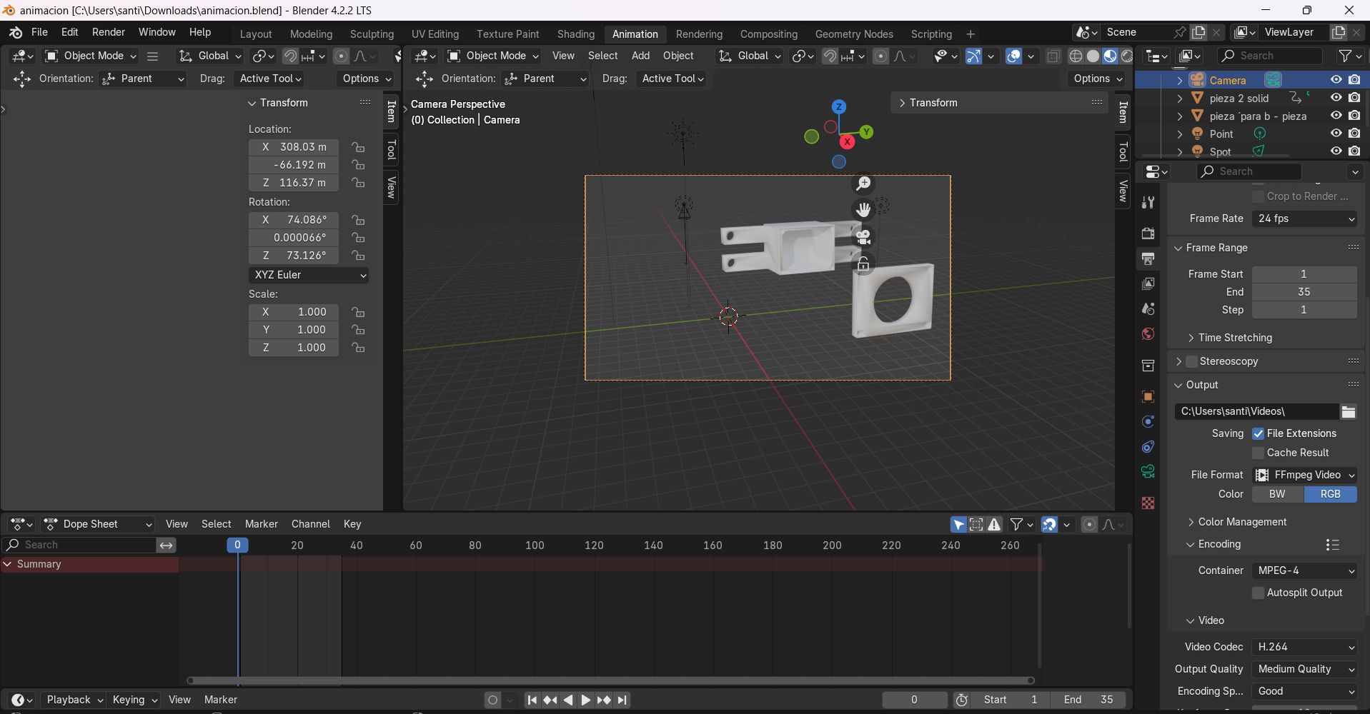
- Adjust the camera and lights to export my animation.
Files
- Download Solidworks file
- Download file solidworks part number 2
- Download Fusion 360 file
- Download Blender file
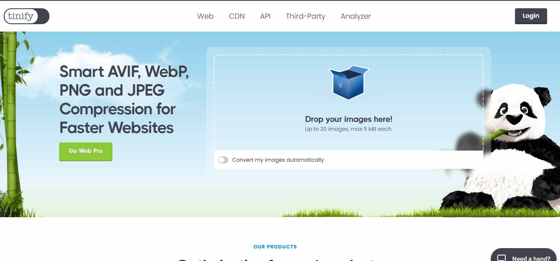
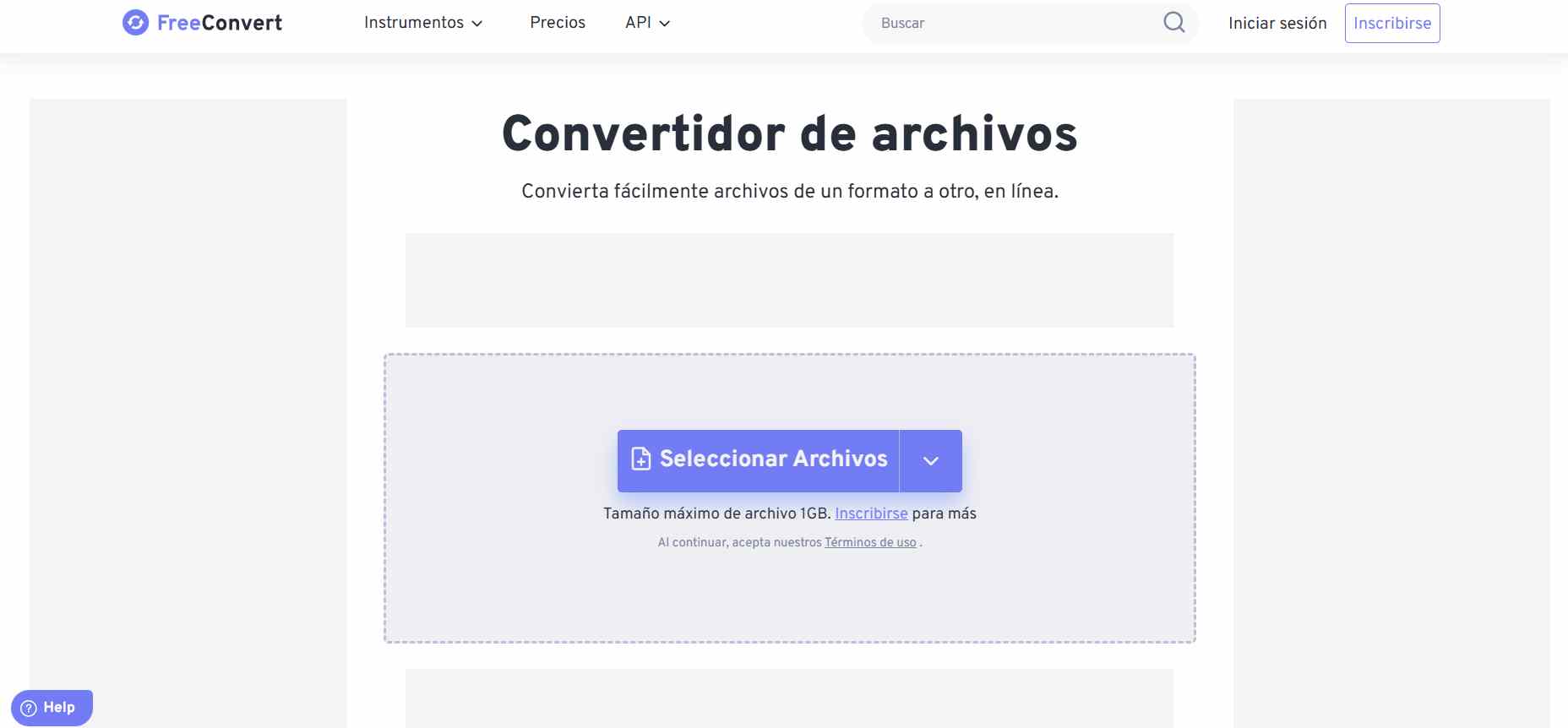
File compression
To compress my files, I used these two websites:
Conclusion
This week I have learned how to use each of these softwares, As for the 2D design, I'm used to working with vectors, so it was very easy to work with them. As for the 3D design the most difficult thing was the design of the box with the measurements and the shape it was going to have, but understanding each tool made it easy for me to make my pieces.