Week 9
Input Devices
Summary
During this week, I focused on exploring different types of input devices and integrating them into a working system. I simulated a gas sensor (MQ2) using Wokwi to validate the connection with a XIAO ESP32 C3 and later implemented real-world tests with an MQ3 sensor and a touch sensor. These activities allowed me to strengthen my understanding of sensor reading, data interpretation, and how environmental changes affect sensor outputs. Practical experimentation and simulation complemented each other, providing a deeper insight into embedded system development.
Group Assignment
As part of the group assignment, we documented:
- probe an input device's analog levels and digital signals
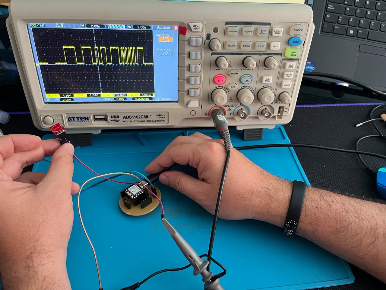
As part of the group assignment for this week, each participant tested a different input device using their custom board. The image and video below show the group testing of the MQ-3 gas sensor, specifically observing the behavior of its analog output (A0). The signal was visualized using an oscilloscope, allowing the team to monitor voltage variations in real time as the sensor responded to changes in gas concentration.
MQ-3 Analog Output Test
Group observation of the analog signal generated by the MQ-3 sensor during testing.
Oscilloscope recording showing the analog voltage response of the MQ-3 sensor.
Oscilloscope recording showing the analog voltage response of the MQ-3 sensor with different trigger.
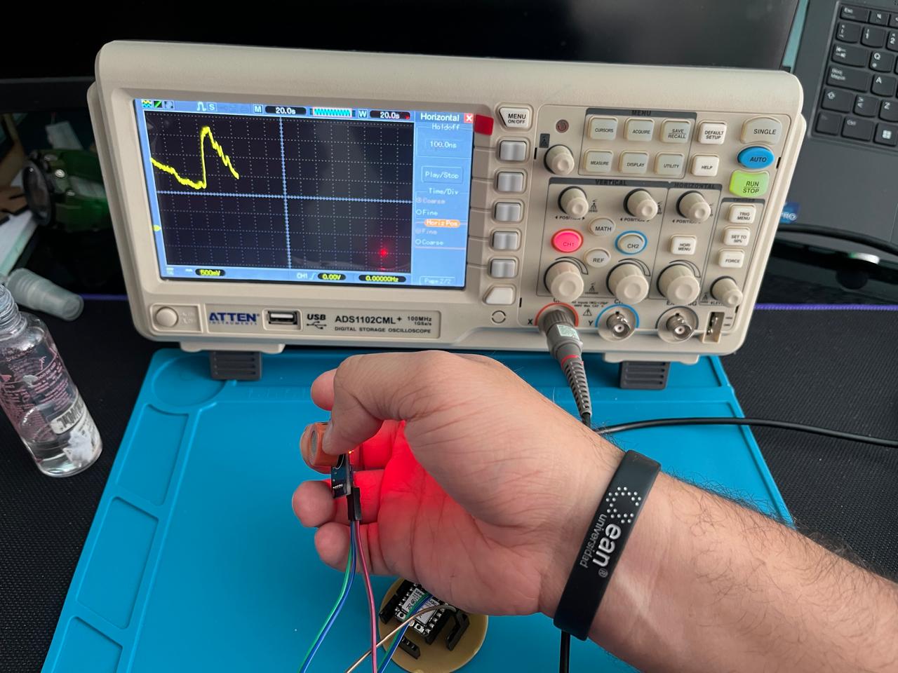
I tested a digital touch sensor using my ESP32-C3-based board. The team also observed the digital output signal generated by the sensor. In this test, the oscilloscope shows a clear transition from a LOW level (0) to a HIGH level (1) when the sensor is touched, confirming the expected behavior of a digital capacitive interface.
Oscilloscope capture showing a transition from LOW to HIGH on the digital output of the capacitive sensor.
Video showing the digital signal change when the touch sensor is activated.
Personal Reflections from the Group Assignment
Participating in the group activity during this week allowed me to reflect on several important aspects of working with input devices:
- I learned to observe and interpret both analog and digital signals using an oscilloscope, which helped me visualize how sensors behave in real time.
- Collaborating with others gave me the opportunity to see different approaches to testing and validation, enriching my understanding of sensor integration.
- By focusing on a specific sensor while others worked on different ones, I was able to compare results and recognize the diversity in input device behaviors.
- This experience helped me strengthen my ability to document and communicate technical findings clearly within a team, which is essential for collaborative prototyping.
Individual Assignment
Input Devices Selection
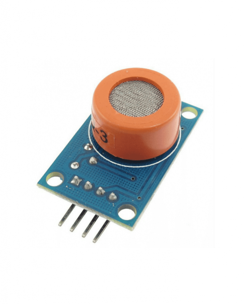
For this assignment, I decided to work with two different types of input sensors. The first is an MQ-3 Alcohol Sensor, widely used for detecting alcohol concentrations in the air. The second is a Hall Effect Sensor, which detects magnetic fields and can be used to identify the presence or movement of magnetic objects.
These choices allow me to explore both analog and digital signal acquisition: the MQ-3 provides an analog output proportional to the concentration detected, while the Hall sensor can be configured to provide a digital high/low signal when a magnetic field is present or absent.
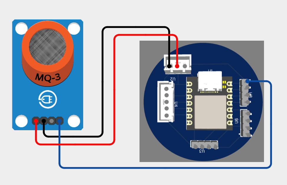
MQ-3 Sensor Wiring
For the first sensor integration, I used the MQ-3 alcohol sensor. This sensor detects alcohol levels in the air and outputs an analog voltage that can be read by the microcontroller.
The connections for the MQ-3 sensor to the XIAO ESP32 C3 were established as follows:
- VCC (Sensor) → 5V (XIAO ESP32 C3)
- GND (Sensor) → GND (XIAO ESP32 C3)
- Analog Output (AOUT) → GPIO2 / A0 (XIAO ESP32 C3)
This setup allows the sensor to continuously send analog voltage readings corresponding to the detected alcohol concentration.
Below is the code implemented to read the analog output from the MQ-3 sensor connected to GPIO2 (A0) of the XIAO ESP32 C3. The analog value is displayed through the Serial Monitor to observe variations based on alcohol concentration.
                // Code for MQ-3 sensor on XIAO ESP32 C3

                #define MQ3_PIN 2 // GPIO2, Analog input A0 on XIAO ESP32 C3

                void setup() {
                Serial.begin(115200); // Start serial communication
                pinMode(MQ3_PIN, INPUT); // Set the pin as input
                }

                void loop() {
                int sensorValue = analogRead(MQ3_PIN); // Read the analog value
                Serial.print("MQ-3 Sensor Value: ");
                Serial.println(sensorValue); // Print the value to the Serial Monitor
                delay(1000); // Wait for 1 second before reading again
                }
Wokwi Simulation - MQ2 Sensor with XIAO ESP32-C3
For the input devices week, I decided to simulate the connection between a XIAO ESP32-C3 and a gas sensor MQ2 using Wokwi. Although in my real project I am using an MQ3 sensor, Wokwi does not yet include it, so I chose the MQ2 as an alternative to illustrate the connection and behavior.
Below you can see the schematic of the simulation that I created to clearly show the wiring:
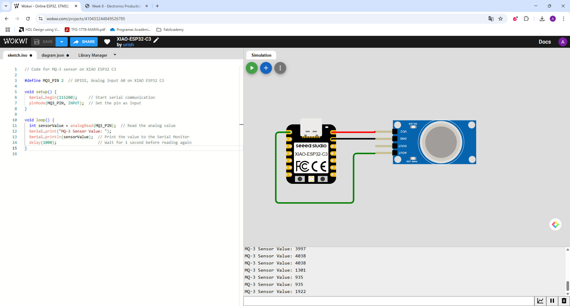
Additionally, I recorded a short video demonstrating the simulation in action, where you can observe the sensor behavior and the data reading on the virtual serial monitor.
Real Test with XIAO ESP32-C3 and MQ3 Sensor
After completing the simulation, I moved on to real-world testing. I programmed my physical XIAO ESP32-C3 board and connected it to an MQ3 alcohol sensor. The programming focused on reading analog values corresponding to the presence or absence of alcohol in the environment.
Programming the Board
The following image shows the code uploaded to the board, using Arduino IDE:
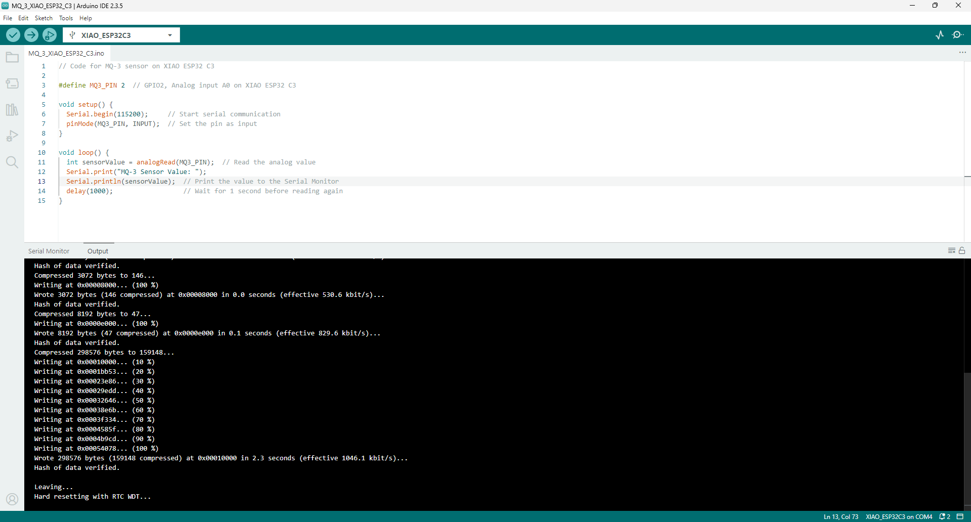
Terminal Output Demonstration
I captured a video where the Arduino IDE serial monitor displays the sensor readings, demonstrating how the values vary depending on the presence of alcohol.
Testing with Alcohol Presence
Finally, I recorded a video bringing an alcohol source close to the sensor. As expected, the readings on the serial monitor increased noticeably when the alcohol concentration was higher, confirming that the system worked as intended.
Touch Sensor Implementation
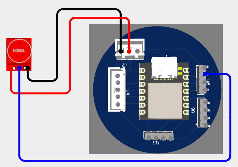
Touch Sensor Wiring Diagram (Wokwi)
For the simulation part, since Wokwi does not have a dedicated touch sensor component, I created a basic schematic that represents how a touch sensor would be wired to the XIAO ESP32 C3.
The connections made were the following:
- VCC (Sensor) ➔ 5V (XIAO ESP32 C3)
- GND (Sensor) ➔ GND (XIAO ESP32 C3)
- OUT (Sensor) ➔ D1 (XIAO ESP32 C3)
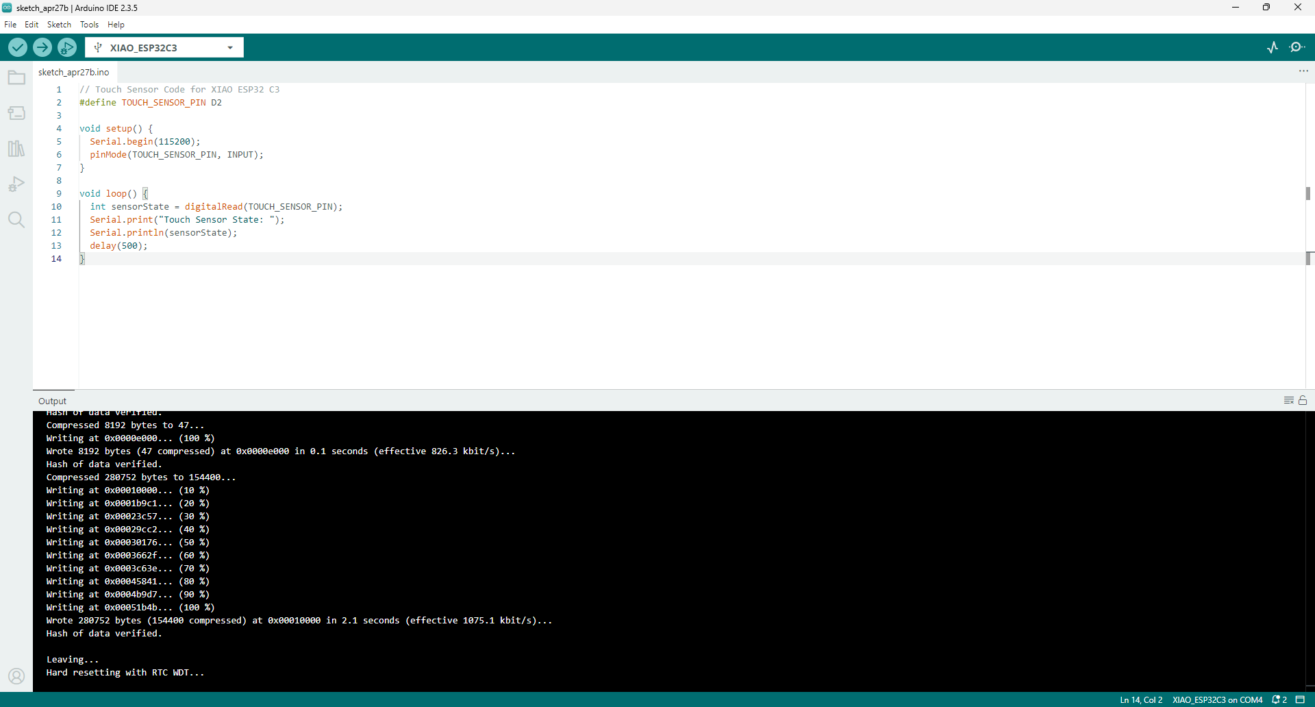
Touch Sensor Code
Here is the code used to read the touch sensor output through the XIAO ESP32 C3:
                    // Touch Sensor Code for XIAO ESP32 C3
                    #define TOUCH_SENSOR_PIN D2

                    void setup() {
                      Serial.begin(115200);
                      pinMode(TOUCH_SENSOR_PIN, INPUT);
                    }

                    void loop() {
                      int sensorState = digitalRead(TOUCH_SENSOR_PIN);
                      Serial.print("Touch Sensor State: ");
                      Serial.println(sensorState);
                      delay(500);
                    }
Real Testing Results
Programming the Board
I programmed the XIAO ESP32 C3 using the Arduino IDE. Below is an image that shows the programming upload process:
Terminal Output
Once the program was uploaded, I opened the serial monitor and observed the touch sensor's output. I recorded a video showing how the terminal displays "1" or "0" depending on whether the sensor is touched or not.
Interaction Test
Finally, I documented a video where I touch and release the sensor while observing the variations in the serial monitor in real-time. This helped verify that the sensor was correctly detecting the touch events.
If you are interested in exploring more input device connections, such as a photoresistor or a push button, you can visit the documentation created during Week 6, where additional examples and simulations are available.
Conclusions and Reflections
Learning about Input Devices: This week allowed me to understand the wide variety of input devices available and their relevance in different applications. Exploring sensors such as the MQ3 and the Touch Sensor helped me gain confidence in connecting and programming devices to interact with real-world phenomena.
Simulation and Practical Testing: Using Wokwi for the preliminary simulation was an excellent opportunity to validate the basic circuit logic before moving to the real tests. Even though Wokwi did not support all the exact components I intended to use, it helped anticipate key aspects of the hardware connections.
Challenges and Problem Solving: Some of the main challenges included adapting the project when exact sensor models were unavailable for simulation and debugging communication issues between the sensor and the microcontroller. Working through these challenges strengthened my ability to troubleshoot and adapt solutions based on the resources available.
Next Steps: Moving forward, I plan to integrate multiple sensors and work with more complex signal processing techniques to enrich the EDUCANSAT project. Continuous testing and refinement will be key to ensuring reliable and accurate data acquisition for my final system.
Downloads and Deliverables
Below are the downloadable resources related to the input Device.