Tasks:
- Group assignment:
- Probe an input device's analog levels and digital signals
- Individual assignment:
- Measure something: add a sensor to a microcontroller board that you have designed and read it
Group assignment
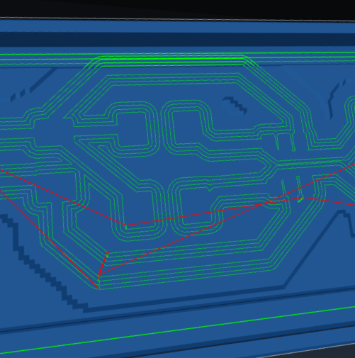
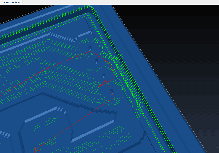
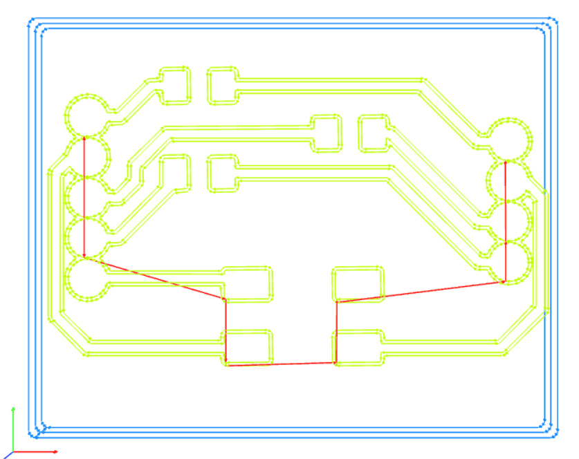
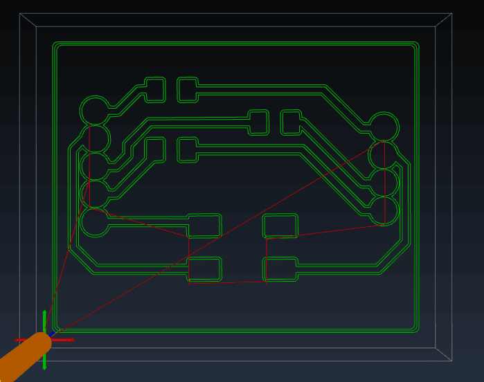
When the nc code gets exported after being processed in Mods CE the edgeCuts seem smaller than the size of the PCB
Solving attempt 1:
Change settings in
I also designed a second PCB, the RGB Button circuit, but that one had the same issues.
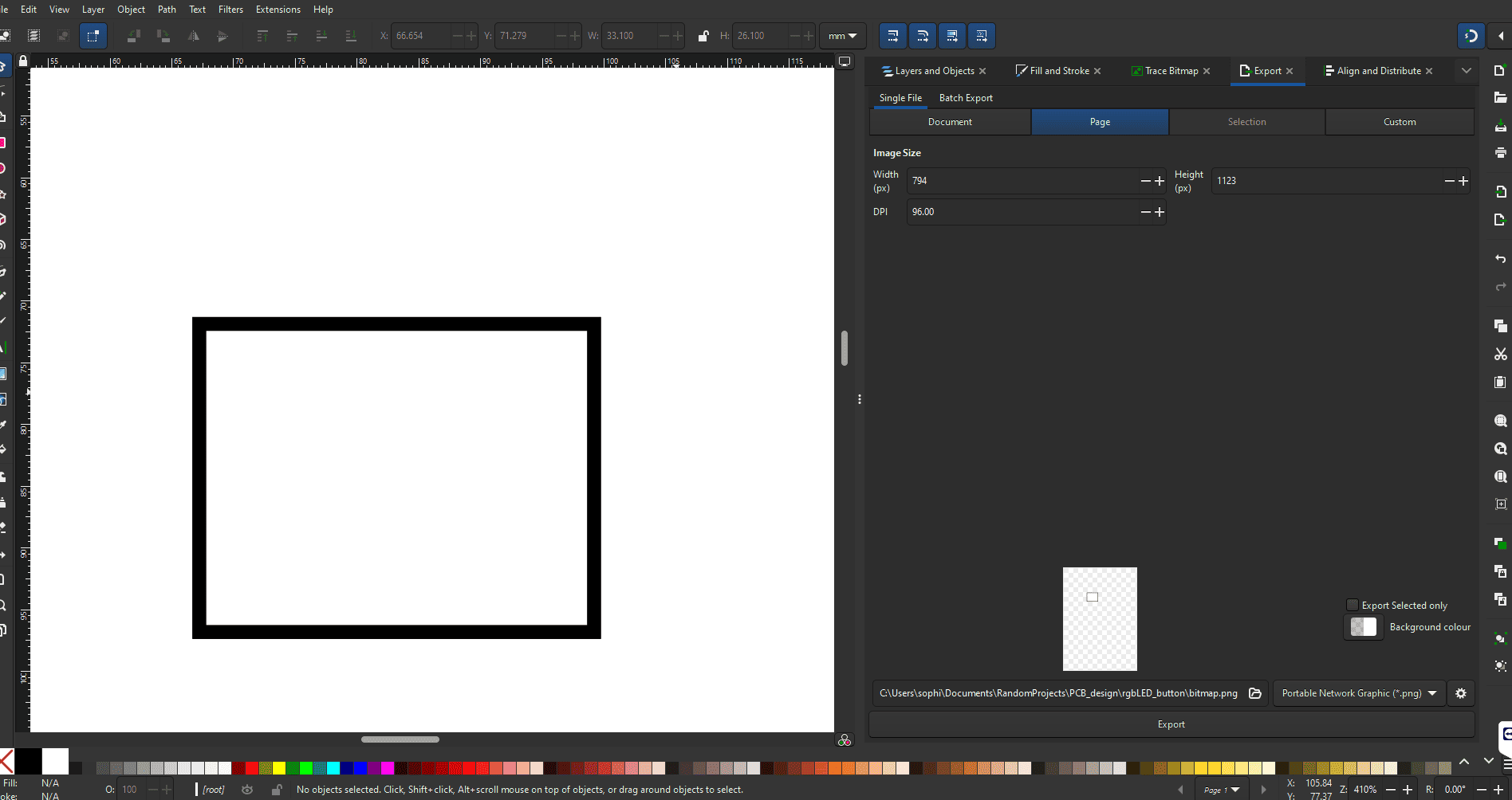
Solving attempt 2:
Change sizes of pictures using Incscape
Solving attempt 3:
My instructor informed me that another student had the same issues. He just went ahead and milled it anyway and it worked.
I find this very weird but worth noting down.
Solving attempt 4:
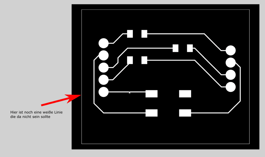
My instructor noticed there was an extra line around the PCB. Through the offset of 4 that line becomes thicker than the edgeCut line.
Therefore: remove that line.
Finally solved it in week 10.
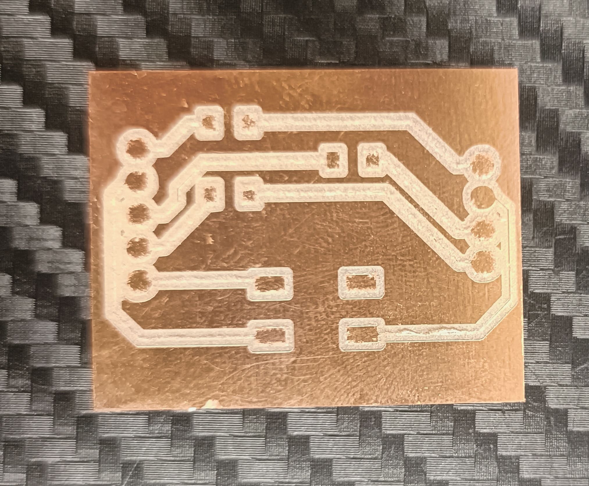
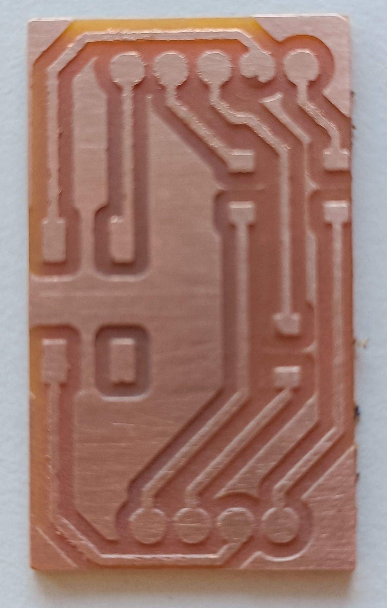
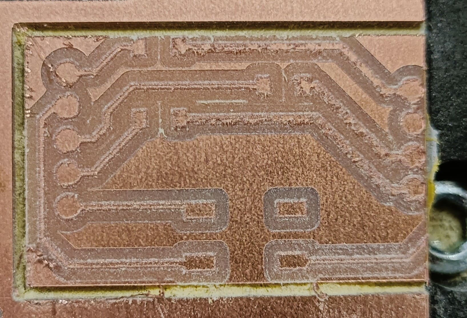
Traces too thin
I forgot to change the width of the traces in kicad. Therefore I milled it 0.2mm instead of the standard 0.6mm. This resulted in the traces being so fragile that they disconnected quite easily (one broke after accidentally washed in washing machine). Learned my lesson, will not do that again.
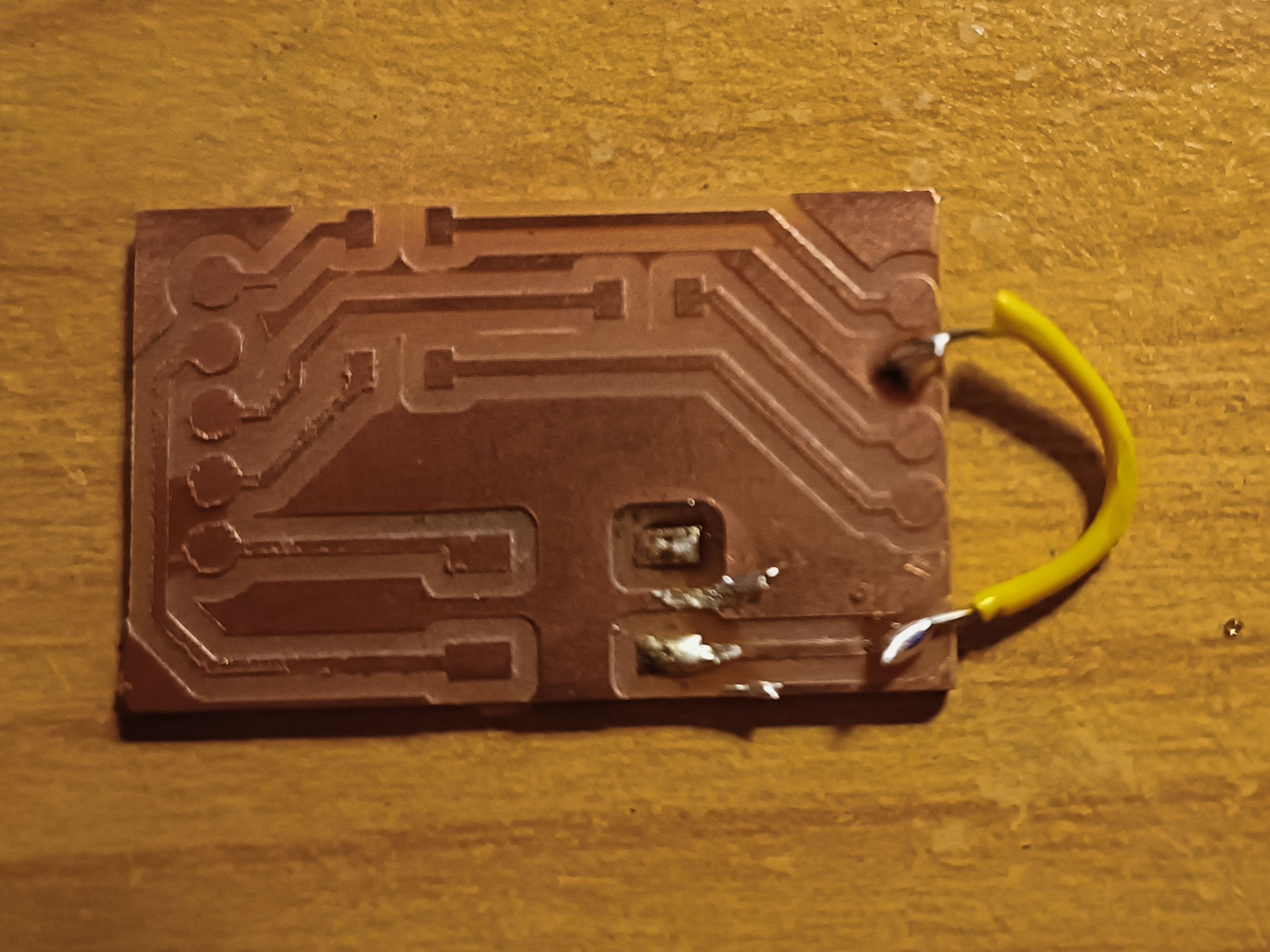
My own inability to solder or make sure to have enough space on the copper plates one of my own PCBs
Download Files
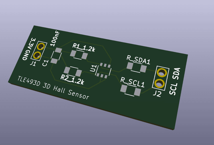
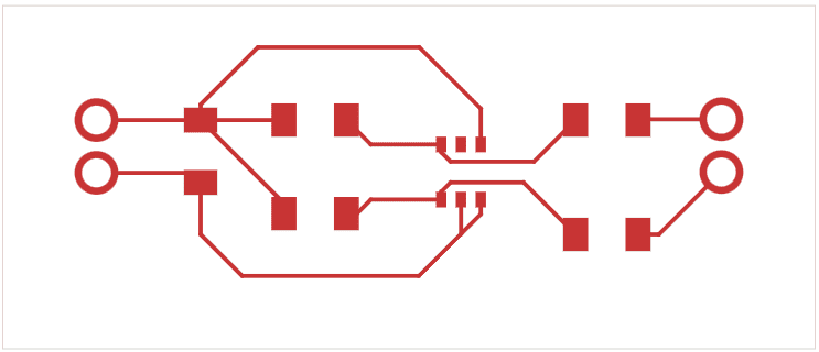
- Download: 3D Hall Sensor KICAD PRO
- Download: Hall Sensor KICAD PCB
- Download: Hall Sensor KICAD SCH
- Download: Hall Sensor Edge Cut GBR
- Download: Hall Sensor F_Cu GBR
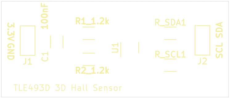
- Download: Hall Sensor F_Silkscreen GBR
Inspiration

3 dimensional RFID tags and readers
Decreasing the amount of RFID modules would considerably simplify the hole system. Likewise, it would not be necessary to use the Pico microcontroller. Instead, a XIAO could be used. Additionally, the cost of the robots would decrease.
In combination with a 3D magnetic sensor the exact position of all surrounding robots could be precisely determined and even differentiated with other objects without major inconveniences in the internal coordinate system. For this, it is necessary that the hall/ magnetic sensor can register RFID waves. Whether this is the case is still to be determined. I am in contact with a professor from TU Ilmenau university to consult this topic.
Boost converters
Check linear Voltage regulators for more information, pngs, and download files.
Button Tests and RFID
Check rgb button schematic for more information, pngs, and download files.